 mmca
mmca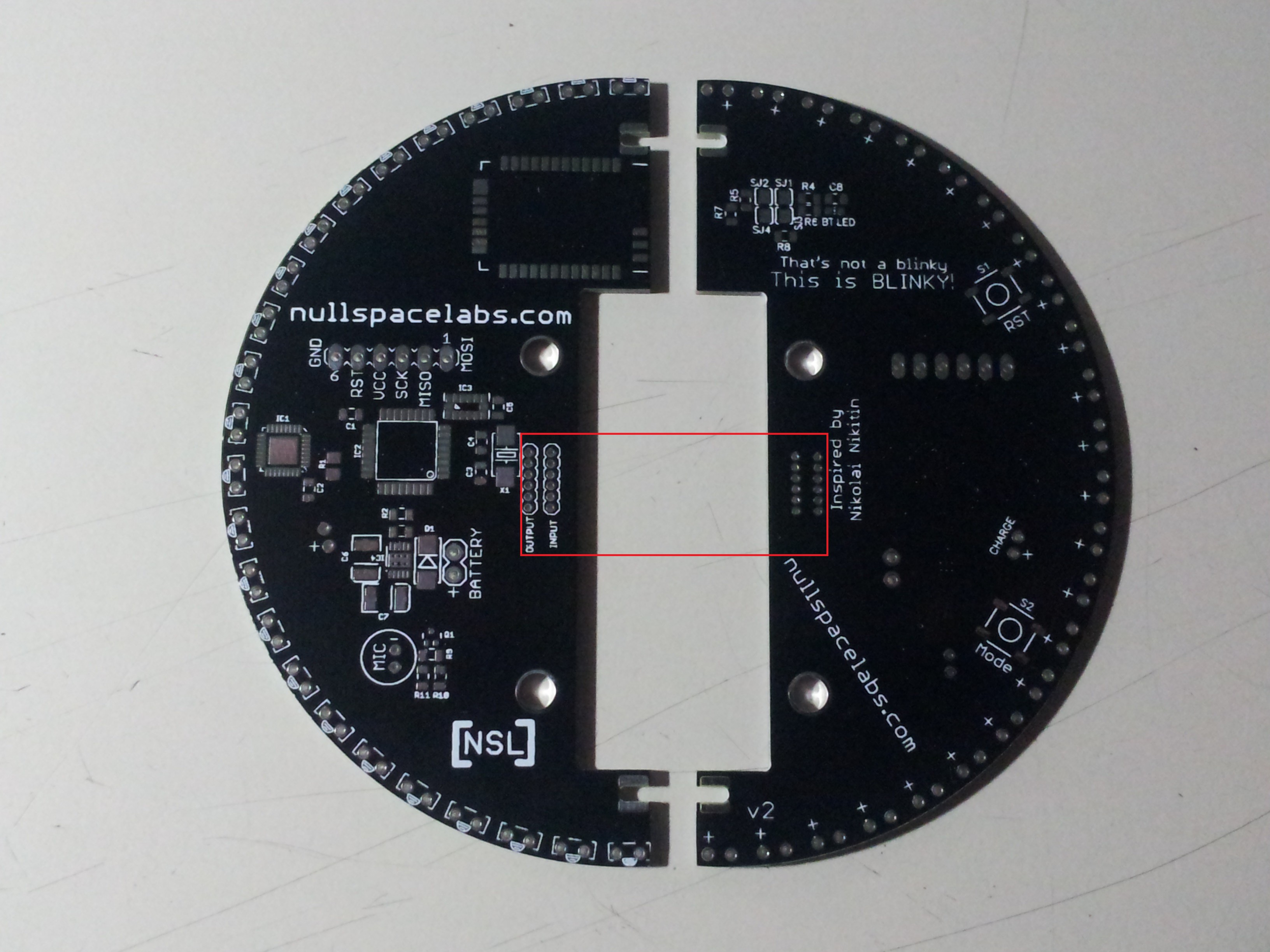 In the first Blinky Ball we used wires to move the power and signal around the ball between slices. It was a little clunky and time consuming to build but seem to work OK.
 For the RGB ball we wanted something a little cleaner, more elegant. So we combined the structure and the signal path. The little slots that are soldered together to make the ball also carry the signals and power.
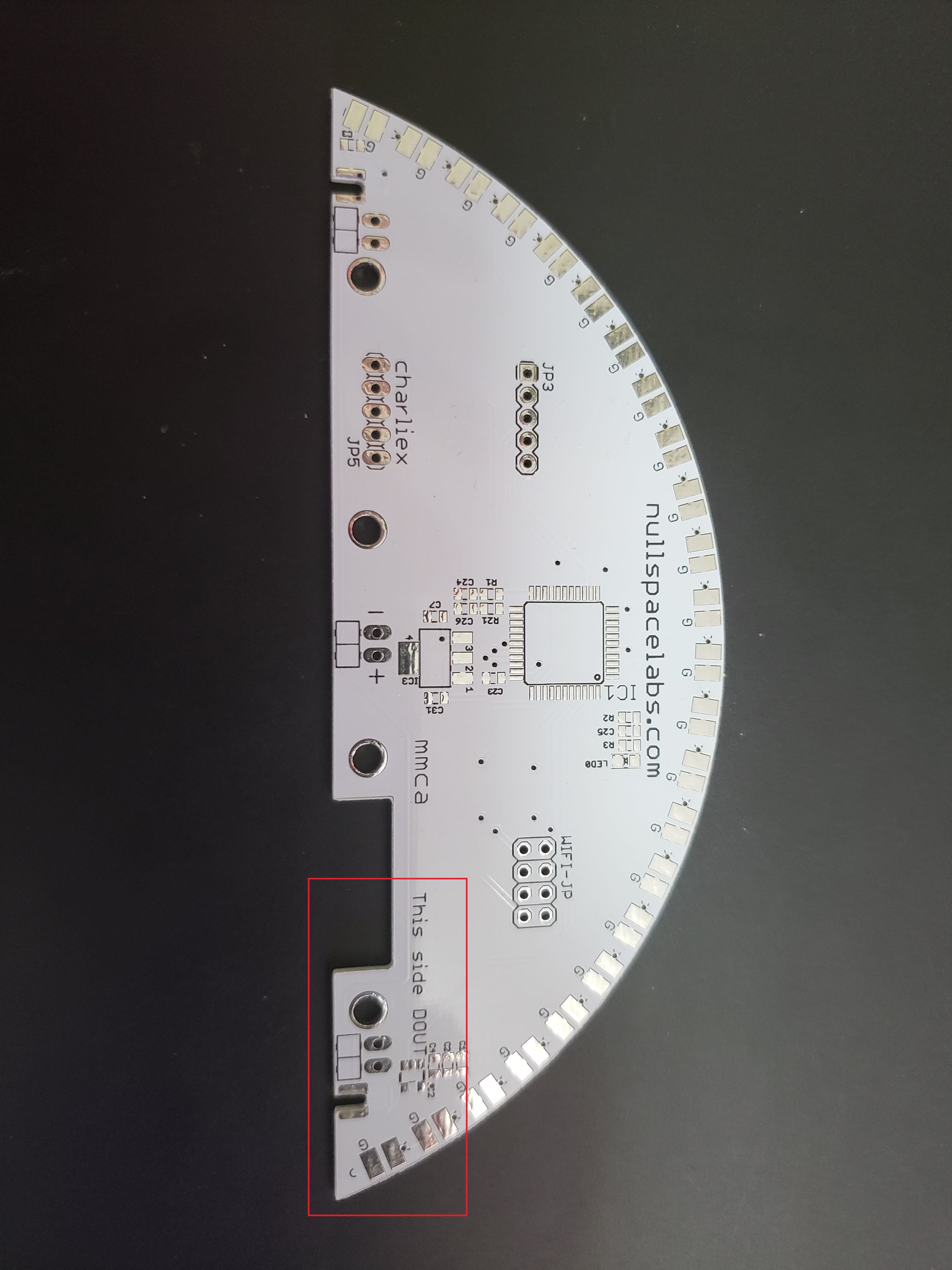
The top cap pass the signal from slice to slice connecting the DOUT from one slice to the DIN of the next. The bottom cap works in a similar manner but is just 5V and GND.
Unfortunately there are still a couple wires in the build. There are user buttons on the bottom cap and some sensors in the top cap that need to be wired. The battery is connected to the power slice by wires and that slice is in turn connected to the power distribution cap (bottom).
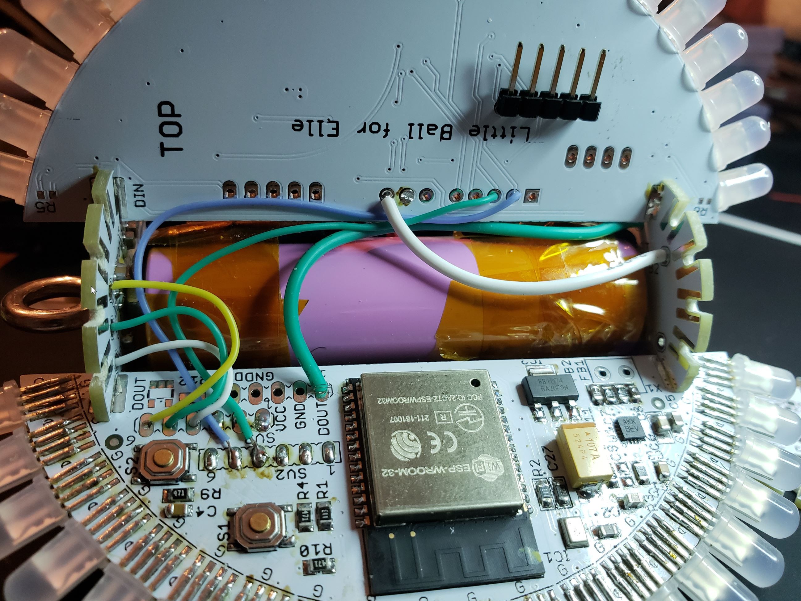
Still needs some cleaning up but its getting there.
Discussions
Become a Hackaday.io Member
Create an account to leave a comment. Already have an account? Log In.