Close
0%
0%

Electronic Barrette Hub

A base station of all your blinking lights

Similar projects worth following

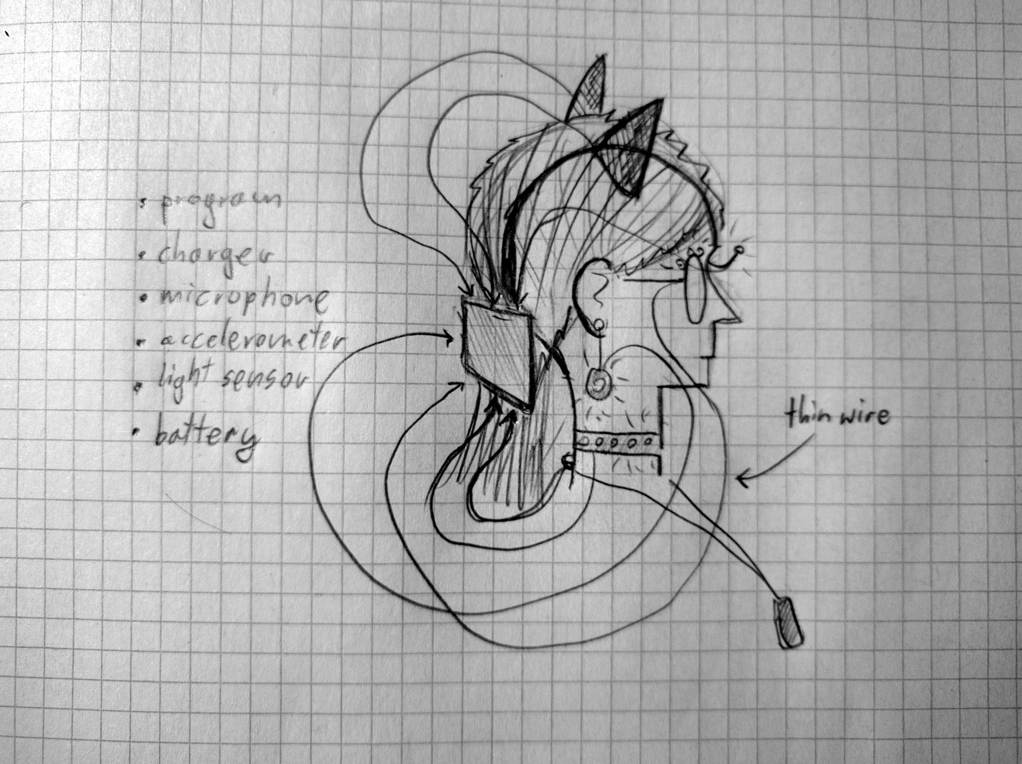
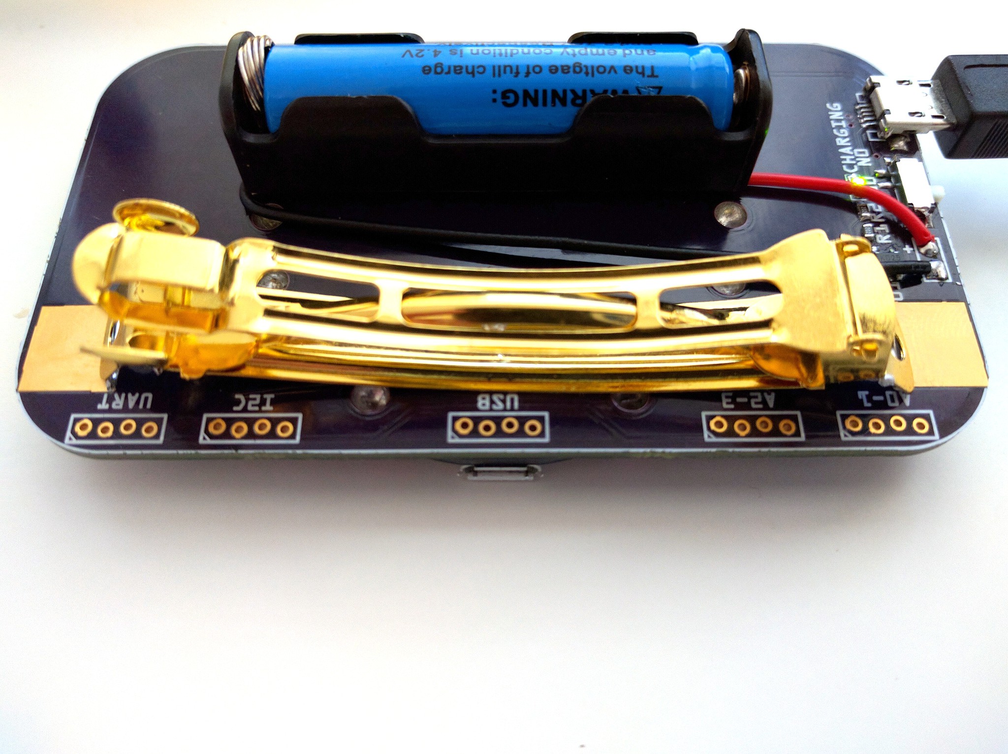
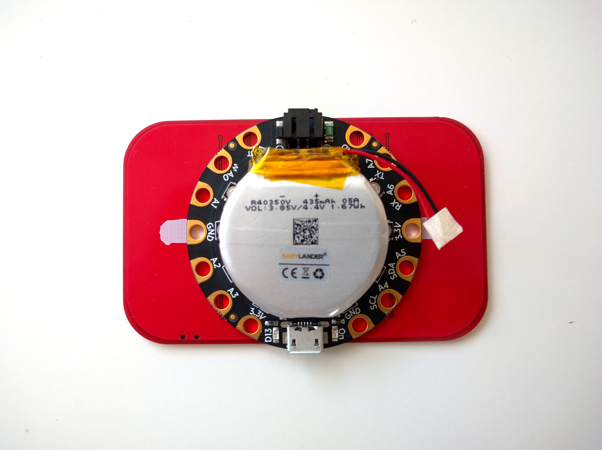
Electronic jewelry is difficult to make, especially when it's supposed to be worn on your head. Things like earrings, hair clips, studs, and even glasses are difficult because of the size and power requirements. There is one accessory that doesn't have such strict requirements: it can be large and relatively heavy, it doesn't touch your skin, and it can fit a rechargeable battery: it's the hair clasp, also known as barrette.

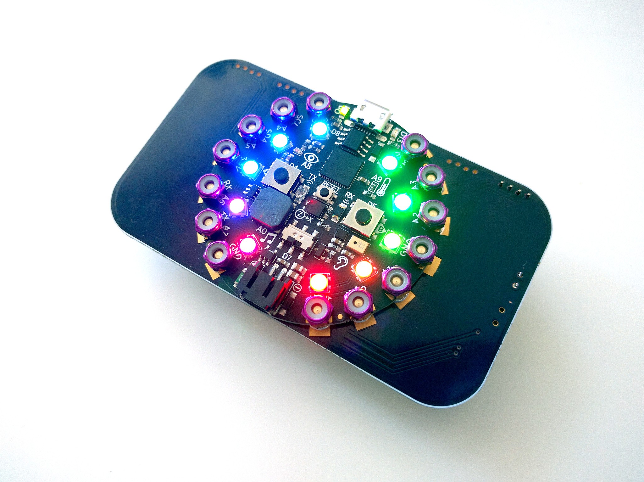
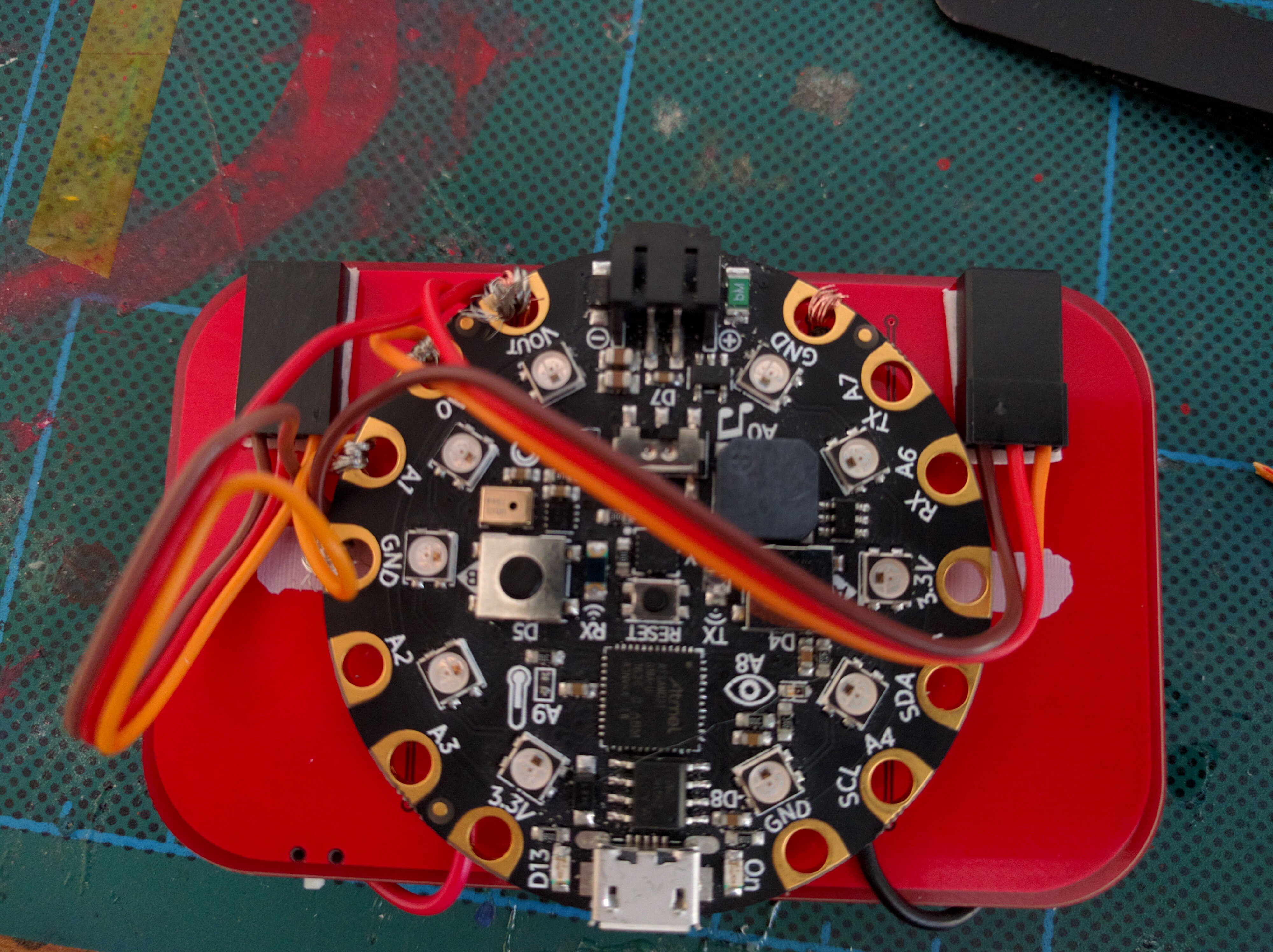
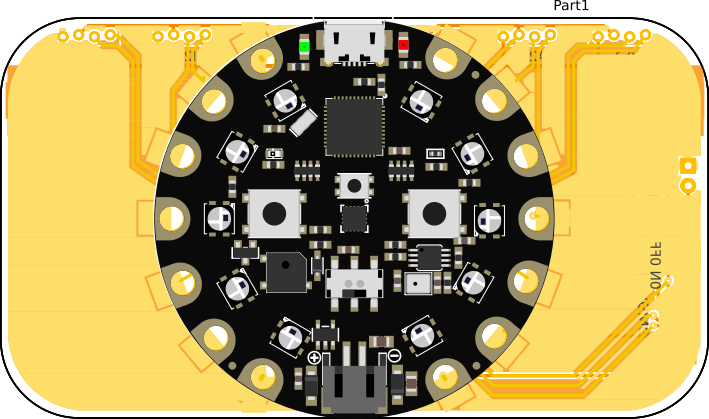
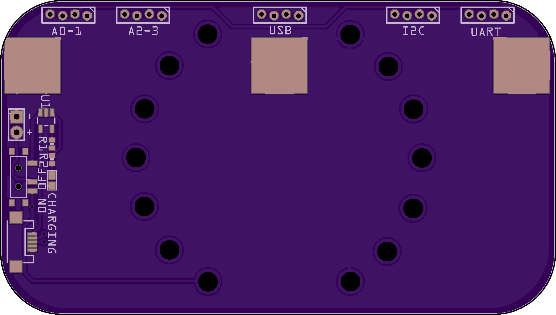
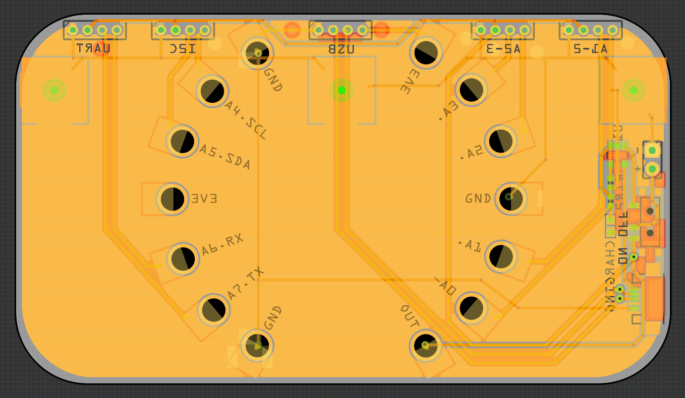
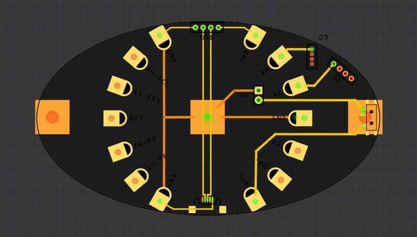
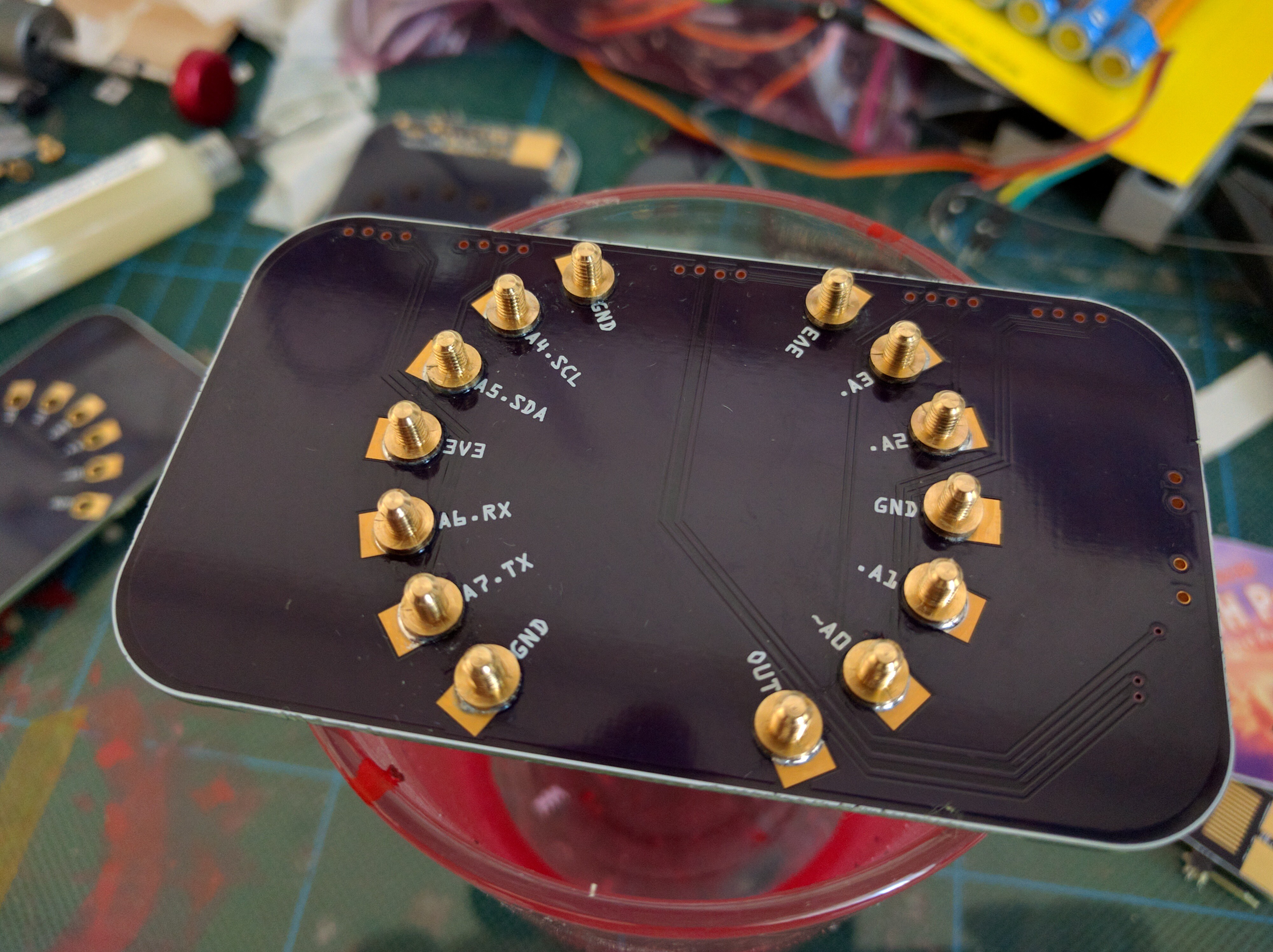
The idea here is to use a barrette as a sort of a hub providing power and control to other accessories on your head. It will contain a microcontroller programmable with CircuitPython, an accelerometer, a light sensor and a microphone — so that you can make things react to movement and sound — and a dozen small sockets, into which you can plug thin wires leading to the actual accessories. You can even have LED eye lashes or #Mechatronic Ears with this!

barrette01.fzz

The Fritzing file for the Pulse Barrette.

x-fritzing-fzz - 75.69 kB - 08/21/2018 at 15:38

Download

View all 11 components

  • Proper Prototype

    deʃhipu10/22/2018 at 10:44 1 comment

    The PCBs just arrived from @oshpark and I finally assembled a proper prototype. I'm quite happy with how it looks, even without the face plate or any ornaments on the PCB:

    In particular, I like how the holes covered with the soldermask look like: inconspicious. I used staggered holes for the connectors, which means that you can simply insert male pin headers into them — you can see one inserted in the top right corner. That really lets me hide them from view.

    There are five connectors:

    Four for general purpose GPIO pins, with two pins on each, also doubling for UART and I2C communication, and one for USB, for those devices (like the #Video Pendant) which are too small to fit an USB port, but still need USB communication. The power on the USB port is stabilized 3.3V, while the remaining ports are connected to the battery directly, because they are likely to need all the power they can get.

    I will do some more testing with those connectors, and if they don't work well enough, I will solder either female pin headers, or grove sockets in there.

    More importantly, the build instructions and parts list are now updated, and there is a bunch of new photos. Unfortunately I won't have time to update the video, but the basic functionality shown there remains the same (well, except for the battery charging, but that's a boring thing to watch).

    The next step will be working on the ornaments and the face plate.

  • What I Hope to Achieve?

    deʃhipu10/21/2018 at 20:38 0 comments

    It's time to talk a little bit about the goals of this project.  On the face of it, there is really very little creativity in it: it's basically just a carrier PCB for the Circuit Playground Express board, with a battery, charger and some connectors. You can build three projects like that before breakfast. There is absolutely nothing novel or revolutionary or technically challenging in here.

    On the other hand, I am not aware of anything like this already existing, and I am convinced that and existence of something like this would be extremely useful for a lot of people. Not just for beginners, who are afraid to try soldering, or designing a PCB like this, but also experienced wearable builders and cosplayers, who don't need to reinvent the wheel every time, and can simply build their stuff around an already existing design.

    If you look at, say, Arduino, it wasn't a "revolutionary" project either. Every single thing on it has been done before multiple times and was widely available. But Arduino made it easier for everyone by bringing those things together in one package, and creating a standard platform to build on, sharing and re-mixing your designs.

    A bare microcontroller board lets you build anything — the possibilities are infinite, and mind staggers confronted with a blank page. A base like the Barrette Hub limits your freedom and suggests what to build — making it much easier to begin, and hopefully bringing more people into the wonderful world of interactive wearables. Later on, when you are more experienced, you can leave it for other, more flexible and universal solutions, but you will probably still come back when your particular use case is a good fit, and a ready solution can save you time.

    Will it work? Will the platform become popular? Will the idea catch on? Will it become an actual standard? I have no idea, this is very much a question of luck and of appearing at just the right time and place. I believe the right time for this kind of platform is closing in fast, and I am willing to do the work to give it a try. Time will tell if it's a wasted effort or not, but in the worst case I still learn a lot in the process.

  • Video and Repository Update

    deʃhipu10/21/2018 at 13:21 0 comments

    In preparation for the deadline, I have now linked the required video in the project's metadata, and updated the project repository with the most recent design files, bill of materials and schematic.

  • Working Prototype (kinda)

    deʃhipu10/20/2018 at 18:49 0 comments

    I have an estimation for the shipping of the PCBs, and it doesn't look good: they will arrive Monday, 3h before the deadline for the prize. So I decided to go and cobble together a working prototype from what I have at hand right now. It's not pretty, but it works, and I can show off some of the possible uses for such a hub in the video, so it should be good enough. I will still attempt to assemble and test the actual prototype as soon as the PCBs arrive, but I can't promise I will make the deadline with that, and I will certainly have no time to shoot the video afterwards.

    I re-used the PCBs for the Pulse Barrette — the simple blinking LED prototype that I made initially — and a lot of two-sided tape. I also used hobby servo plugs for connectors, and only wired two pins (the final version will use all 8 pins). It looks like this:

    I also updated the BOM and the build instructions. Of course, those will change as soon as the final prototype is ready, but since I don't have the PCBs, I can't make the photos, etc. — so you have the crappy prototype instructions for now.

    You know, it may actually be more fun to build it like this, even if it looks bad.

  • Making Holes

    deʃhipu10/18/2018 at 16:06 0 comments

    While waiting for the PCBs (they might not make it in time after all, I'm afraid), I'm still working on the faceplates. In order to correctly place all the holes for the CPX's LEDs and sensors, I prepared an image of the PCB with the CPX overlaid on top of it (lifted from Adafruit's Fritzing library):

    Then I printed that on normal paper, and used a knife to cut out all the places where there is something that needs to be exposed. Then just align it with the outline of the faceplate, and gently shade the whole thing with a pencil:

    The last step is just a scrollsaw and a dremel tool. You can also see on this photo the cool purple bolt nuts that I found, to be used to secure the CPX to the board.

  • Replaceable Faceplates

    deʃhipu10/16/2018 at 14:55 0 comments

    While waiting for the PCBs, I decided to work on an idea one of my friends had for making this look less intimidating and technical: faceplates. Basically, instead of making the PCB itself look nice, which is a challenge in itself, I can simply cover it with a faceplate made of some lightweight but nice-looking material. For prototyping I'm going to use some plywood that I have handy, but nicer woods and other materials could be used instead.

    So I fired up my trusty scrollsaw, and cut myself two faceplates:

    The next step is cutting the holes for the multitude of controls and sensors on the CircuitPlayground board — we don't want to have them completely covered. It's going to be a bit of a challenge, I think, but hopefully I can make it work.

    The plan B if this doesn't work is to paint the plain PCBs that I have ordered with golden acrylic paint by hand, to simulate the patterns that would normally be etched on the PCBs in the fab.

  • Sent to Fab

    deʃhipu10/15/2018 at 17:51 0 comments

    The PCBs are ordered, and should arrive sometime this week. There isn't really much fancy stuff going on on them — just a few connectors and a battery charging circuit.

    I played a little bit with a trick that lets you do covered vias in Fritzing — you basically remove the vias (or other elements) from your design, generate the gerbers on the side, and copy just the mask and silk layers. This way I made the holes for the CPX bolts covered with soldermask on the bottom side:

  • Not Dead Yet

    deʃhipu10/13/2018 at 21:42 0 comments

    There has been no update for a long time here, and that's because there hasn't been much work. Why not? Because I was out of ideas. You see, I really want this to look good — to not be a horrible mess of tangled wires and electronic components, even though that is sometimes nice too, if you are into that kind of aesthetics. But that is surprisingly hard to do. And now, that the project has qualified to semifinals of the Hackaday Prize, there is even more pressure to get this right. I've been avoiding this project, focusing on my day job and other projects, because it was simply stressful.

    But now that there is a little over one week left for the deadline, I remembered (again) that the secret to getting something right is not in getting it right at the first try, but in trying a lot of times and improving with every iteration. So yeah, the prototype doesn't have to look good, even though I will make it with that goal in mind. I just need to get back to trying out things.

    So I went and finished the PCB design. Based on the feedback from the non-smart barrette users, I went back to the same size and shape. I also decided to make it as flat as possible, and use a standard shaped LiPo battery after all (even though the round one arrived some time ago) — that will make the build easier to reproduce. So here is the carrier board:

    There is a battery connector, power switch, charging electronics and USB port (for charging and for interfacing with the #Video Pendant). Instead of eight connector, each with one signal pin, I switched to four with two pins each — and they are arranged according to the Grove connector standard from Seeedstudio. Using standards where possible will make it more versatile in the future. Maybe I will even switch to the JST connectors, then it will be fully Grove-compatible.

    I left the holes for the CPX, but I will probably cover them by soldering bolts onto them — so that the back is flat, because otherwise they would interfere with the hair clasp, and possibly also tangle into the hair.

  • Power and Connectors

    deʃhipu08/26/2018 at 10:43 0 comments

    Once I decided to use the CircuitPlayground Express board, everything else clicked in place. The battery will need to be sandwiched between the carrier board and the CPX, because the other side of the carrier board is pretty much dominated by the barrette itself. That means I need a relatively large battery that will fit in there. Something like this:

    There will be a second USB port on the carrier board for charging the battery and for programming the addons (this way the addons can have a less troublesome connector on them, that you will connect to the carrier board for programming).

    There will also be 8 sockets for connecting the individual addons for wearing. Those sockets require some thought. On one hand, the plugs need to be small and light, because they will be most likely attached to almost invisible magnet wires, and we don't want that to break. On the other hand, they need to be easy to connect and disconnect, because you will be likely doing it while the barrette is at the back of your head already. Finally, they need to be keyed, so that you won't connect anything in reverse and burn it.

    I was looking at various molex, jst, servo and other connectors, but they are usually rather expensive, bulky or require large force to connect. Finally, I decided to simply use 1.27mm female pin headers on the barrette side (female, because they expose power, so you don't want any shorts there), and male pin headers with heat-shrink tube as plugs.

    What about keying them? Well, as you can see, the assembly is asymmetrical, so all I need is some physical obstacle on the side where the cable is not supposed to go. Like a single male 2.54mm pin, for example.

  • Reuse

    deʃhipu08/20/2018 at 22:46 0 comments

    It's been a little bit frantic the last few days, and I didn't really have much time to work on this project, but I decided to at least write about what the plans are.

    First of all, the "dumb" blinking barrette has been given to a number of people for testing, so that I will know if this general size, weight and attachment method are practical. I still have a few left, I might put them on Tindie when I find a bit of time to make proper photos and write the description.

    Second, the "smart" barrette is supposed to run CircuitPython and have a bunch of sensors built in — pretty much like the Adafruit's Circuit Playground Express, except with a battery, a charger and some standard of sockets for all the devices. So... why not just use the Circuit Playground Express, and make a base board for it with the battery, charger and the sockets, and the barrette, of course? That would save me a lot of work and testing, and it would still look pretty interesting. So that is the current plan. I found a nice round LiPo battery, and I started to design the PCB for the base:

    I still requires more work, of course — maybe when I have another sleepless night.

View all 13 project logs

  • 1
    Attach the bolts

    We will start with the hardest step: attaching the bolts. For this step you will need a second PCB or another kind of template to hold the bolts for you. Insert all the bolts into the holes:

    Then cover it with your actual PCB, making sure the front is downwards. Secure it with rubber bands, and fill the holes with solder paste:

    Then take your soldering iron, and melt the paste in every hole, stirring to make sure it all melts and catches the bolt properly:

    Finally remove the rubber bands and template and wash the excess flux and paste with acetone:

  • 2
    Bend and solder the barrette

    Next bend the the barrette's ends so that they are inline with the middle, and tin them, then solder it in place.

  • 3
    Solder all remaining components

View all 5 instructions

Enjoy this project?

Share

Discussions

morgan wrote 10/22/2018 at 18:43 point

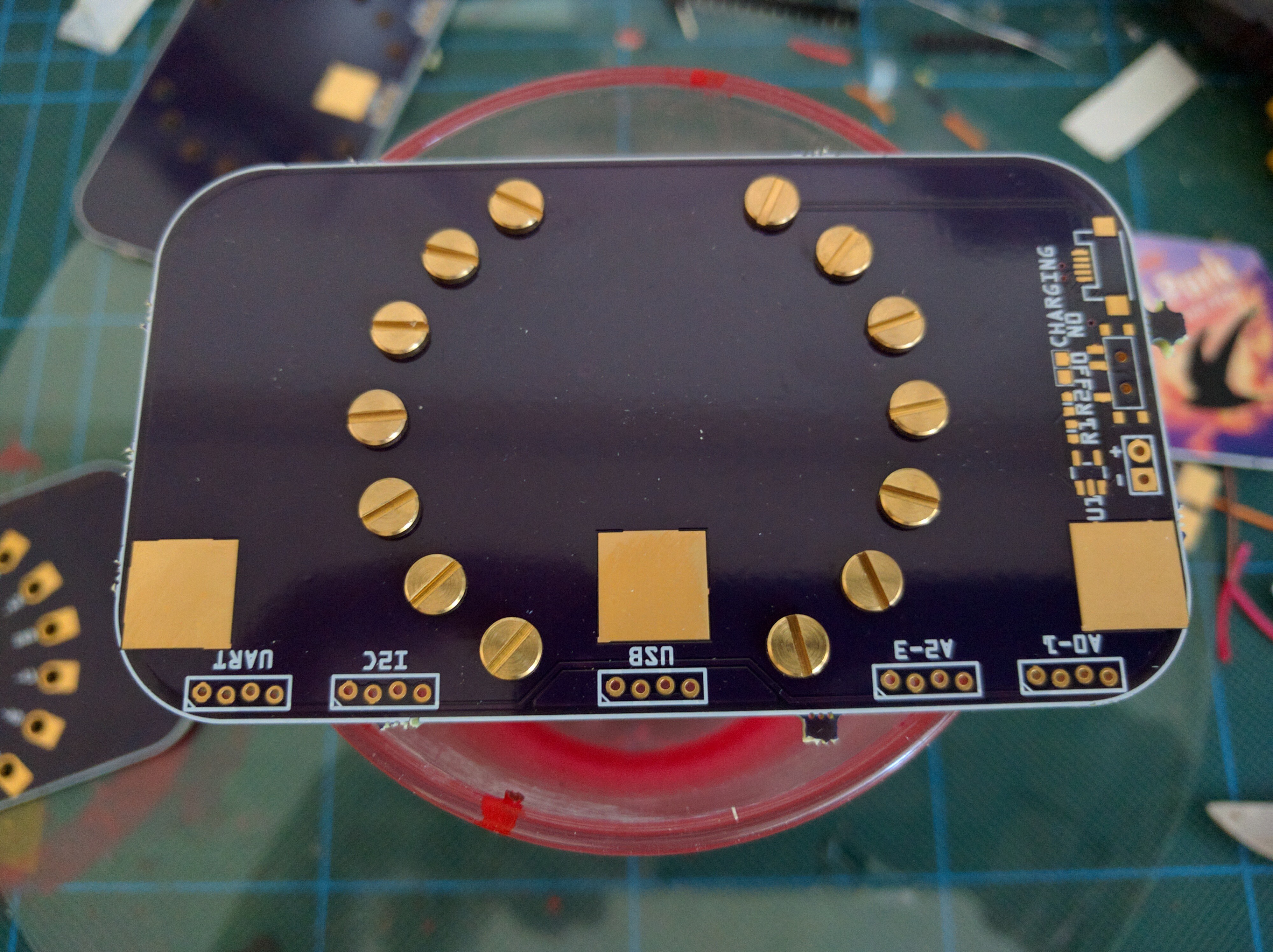
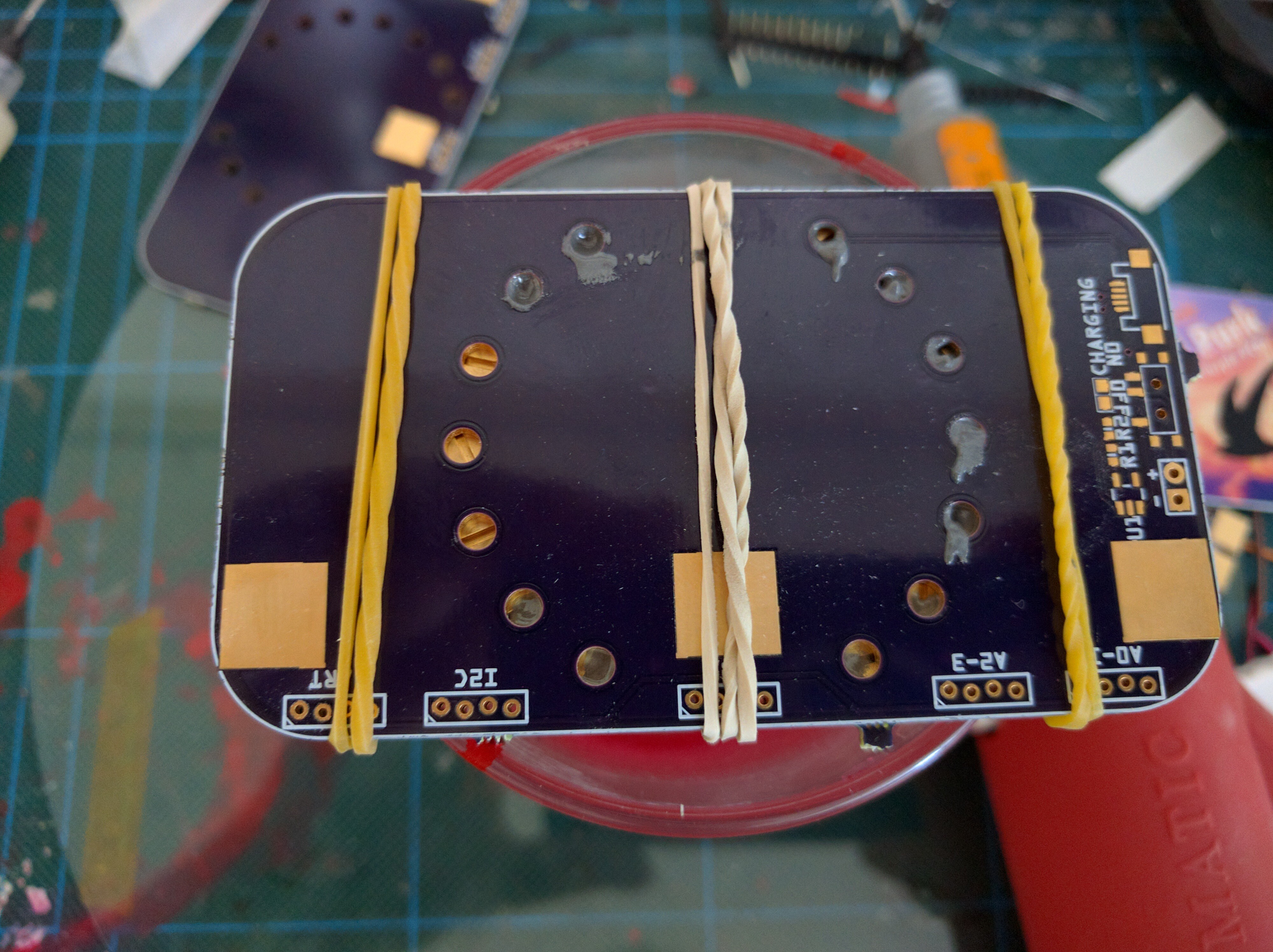
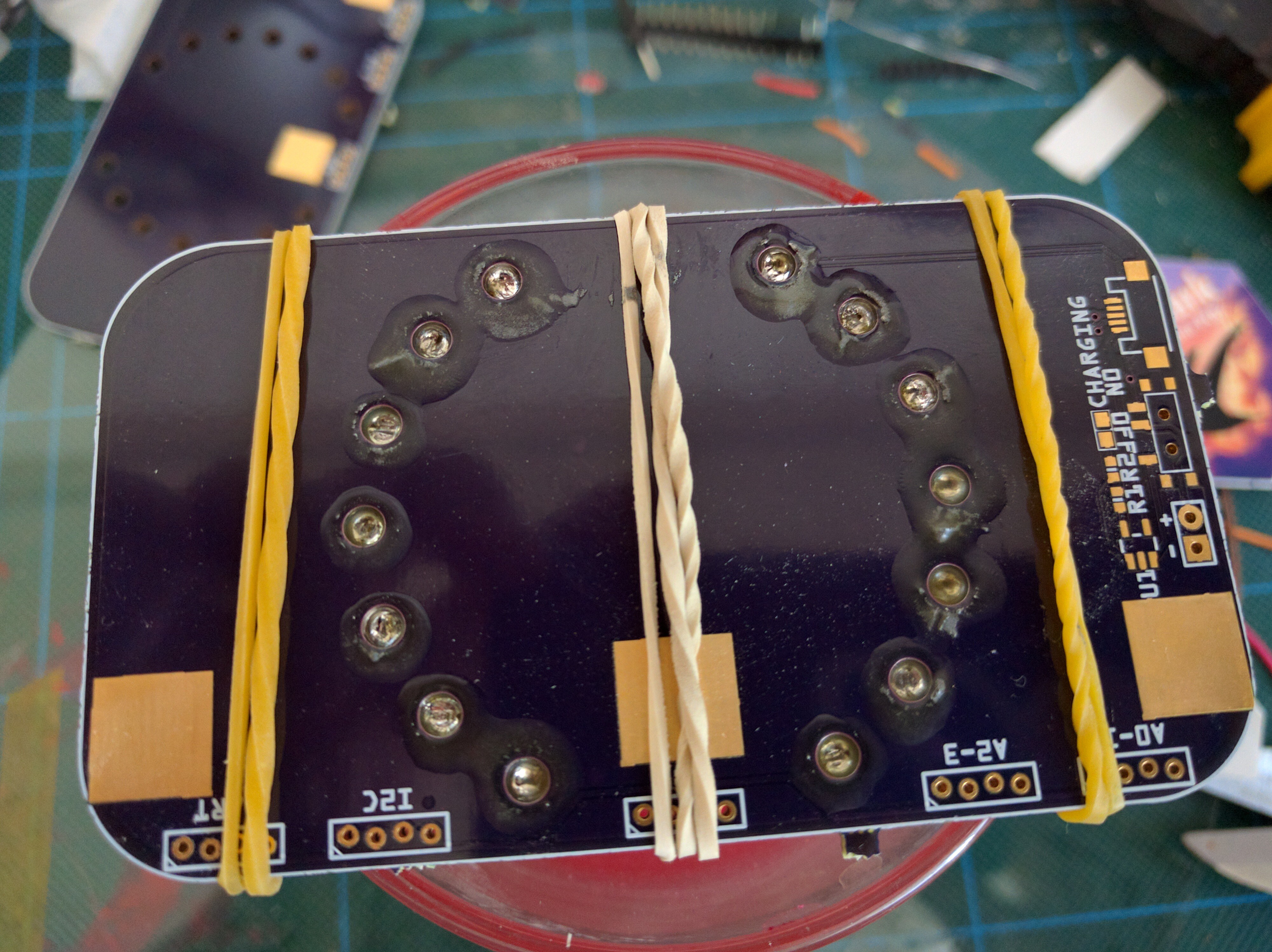
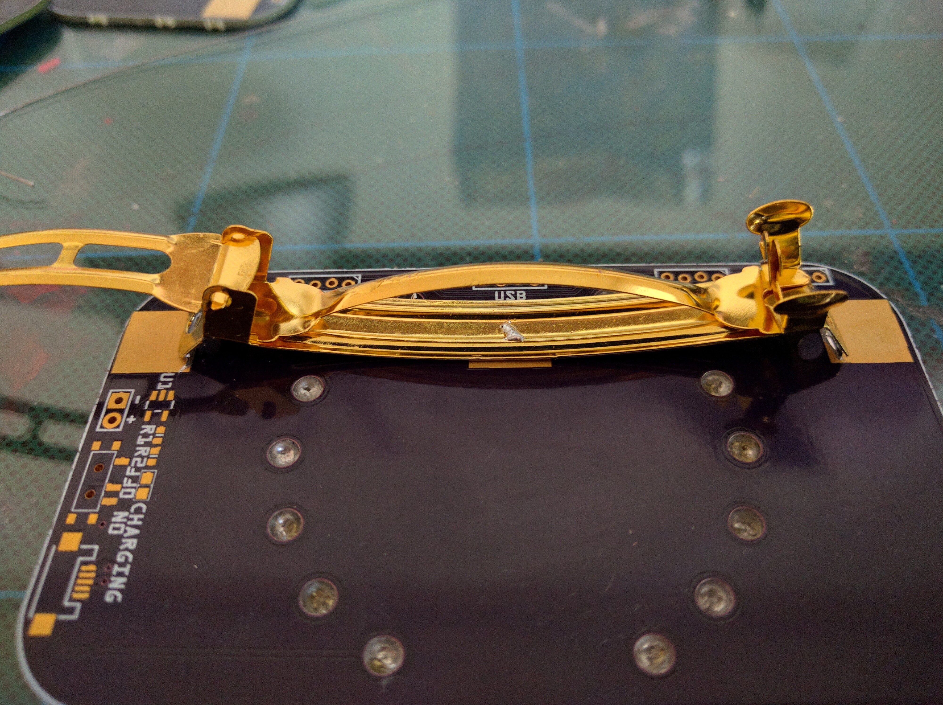
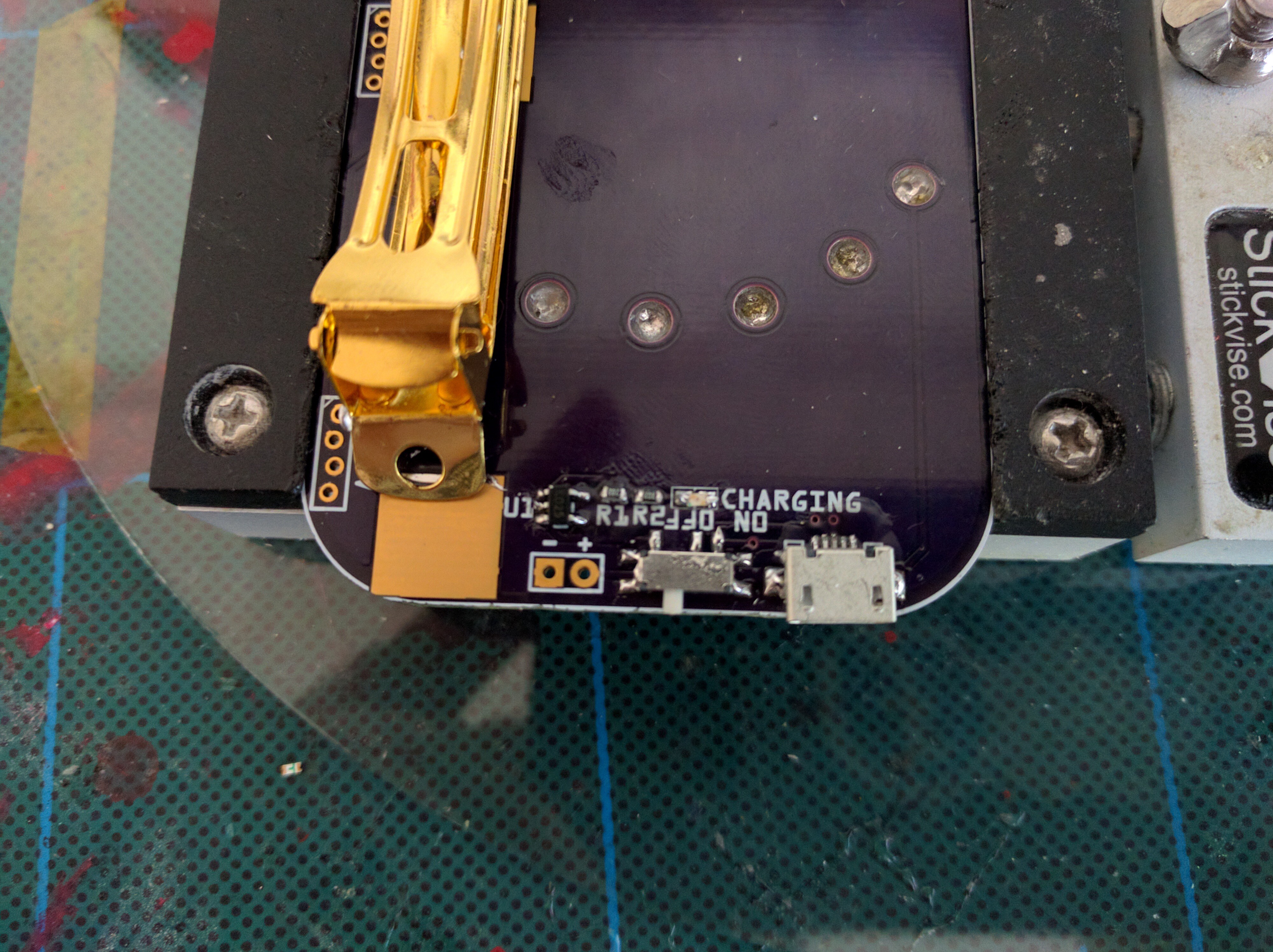
Those soldered down bolts are amazing touch, and then purple anno bolts?!? That's extra style for days. Nice work.

  Are you sure? yes | no

Similar Projects

Does this project spark your interest?

Become a member to follow this project and never miss any updates