 Xasin
XasinNo time? At least look at the intro video:
And a demo of one of the sensors, the gyroscope:
https://twitter.com/XasinTheSystem/status/1453095741501620230
Or a demo of the tap and twist input methods!
https://twitter.com/XasinTheSystem/status/1455661802298150916
And a little debate timer, a first practical use case:
https://twitter.com/XasinTheSystem/status/1460379972506423305
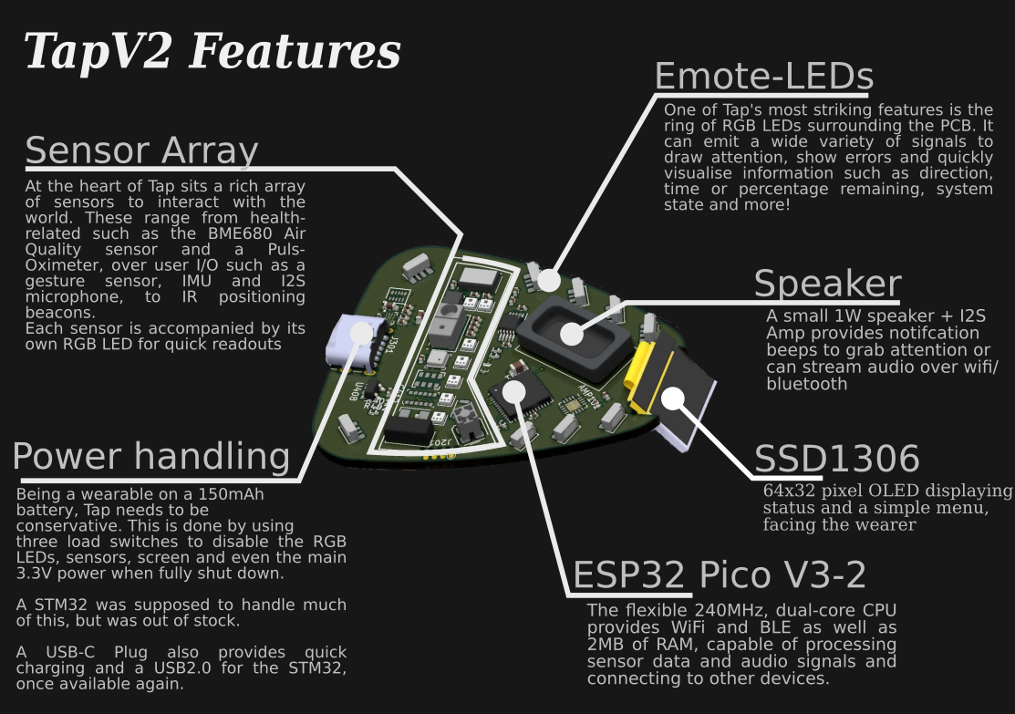
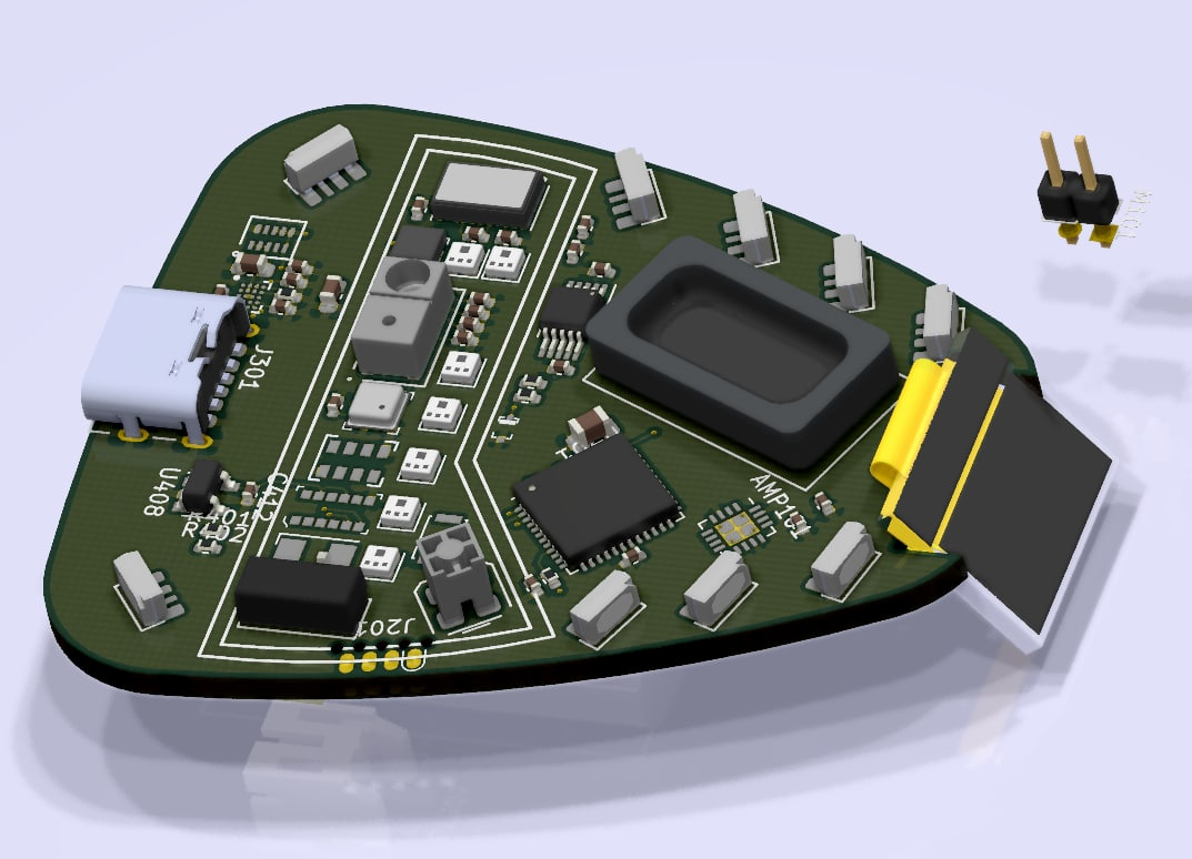
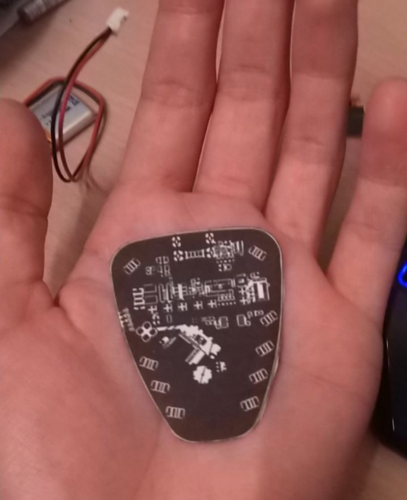
But what even is this?
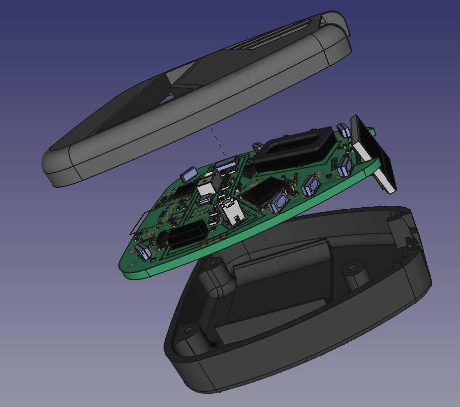
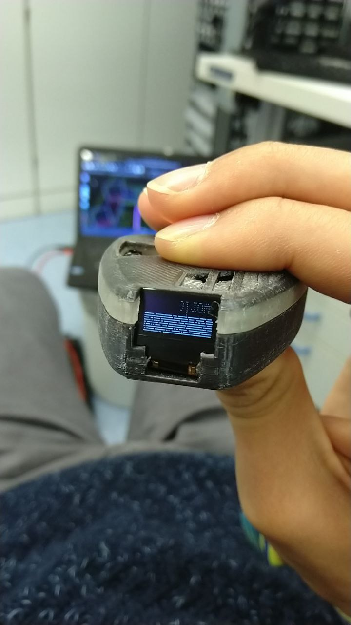
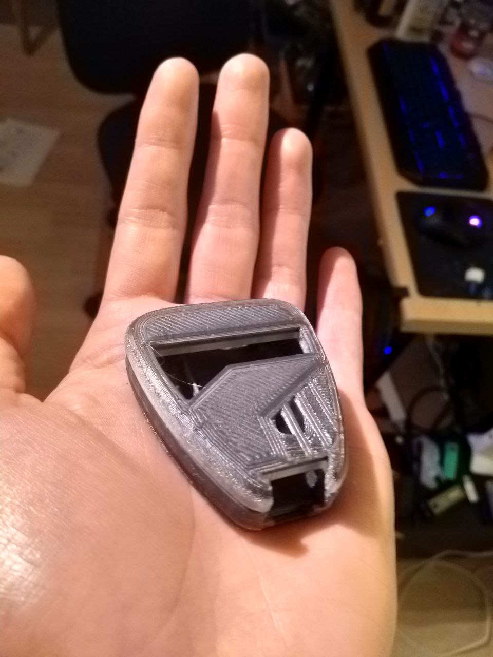
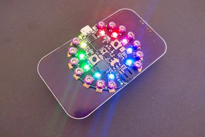
And a casing:


 deʃhipu
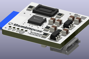
 Matias N.
 Jean Simonet
 akupila
Phenomenal design, very ambitious. Shame that component shortages are slowing things down, but very excited to see the project progress farther.