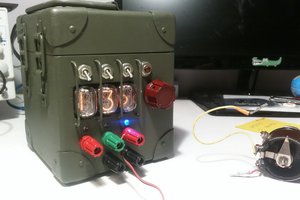
Here it comes the hard point: once decided that this will be a boost-type power supply, the hard point is the selection of the PWM controller IC. In the jungle of the DC-DC controller chips, we have to consider:
Integrated or external switching MOSFET
Slope compensation
Soft-start capability
Switching frequency solution (up to 1 MHz)
Overcurrent detection
Packaging of the IC
Maximum ratings of voltage and current
Since the idea is to build something new, all the usual design are not the way. This rules out the commonly used chips for nixie power supplies:
MC34063
MAX1771
MAX771
UCC3808
555 timer-based solutions
... but makes the journey more interesting !
So what are we looking for ? To begin:
A chip by Linear Technology, in order to have a model in LTCSpice to simulate it. If you are new to LTCSpice you can take a look to the numerous tutorials, like this.
A package that can be soldered by hand, so no packages without leads ... and I don't even mention the ball bonded ones
What I want from my power supply is to be able to drive a nixie clock, so more than 4 tubes.
So the key requirements are:
DC-DC boost converter
Vin 5 or 12 V
Vout around 170 V
Iout around 50 mA
Now, the idea is to build a boost converter and not a flyback one. This is because for me it is more challenging the boost type and there is no need to use a transformer. In the future maybe I will design also a flyback transformer, eventually involving voltage multiplier stages.
The great design step-by-steb explained by surfncircuits
the idea is to take a lot of inspiration from these great guys, but building something new. So I will use a different IC from the ones that are commonly used in the examples online.