 sjm4306
Dave Jones' video series on designing a nixie display inspired me to finally get off my behind and build the nixie clock I always wanted. That plus a PCB manufacturer, JLCPCB, approached me to sponsor this project and video, so I really had no excuse to not cross this off my todo list.
I threw together the double sided pcb in eagle, and the pcbs I received from jlcpcb are amazing for the price they offer in such short turn around time (it must have only taken three days for production and less than a week to arrive in the mail). Check them out here: https://www.jlcpcb.com//, I've seen them everywhere recently pushing to support hobbyists like me with our projects. I ended up routing absolutely tiny 4-5 mm traces with tight clearances and the boards came out flawless. This was only the third board I've ever designed and ordered (and was the most complex and admittedly least optimized) and I couldn't be any happier with how they turned out. On the eagle side, I learned a lot about keep outs, and segregating different planes on the same layer by priority.
The software is written in C in MPLAB for the PIC16F886, compiled with High-Tech C. The SPI for both the two 32 bit chained serial shift registers (HV5122 to drive all the digits) and real time clock (DS1302, which is supercap backed) are both bit banged so the firmware can quite easily be ported to just about any other mcu. One gotcha was the chip I chose has 12V logic input so while it might have worked with the 5V from my PIC I opted to use a simple npn level shifter and invert the logic in software. I added a simple menu system to adjust things like daylight savings and an adjustable roulette function to prevent cathode poisoning. I have plenty of flash and I/O left so it would be trivial to add future features like wifi to auto set the time from the internet.
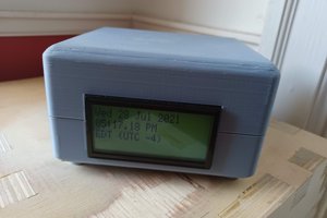
I ended up using a cosmetics container for the case as it is clear so you can see all the internal goodies and just so happened to be the perfect size. I did have to 3D model and print supports to hold the pcb up and secure. I added screw holes and planned on securing it that way, but apparently friction is sufficient.
The biggest things I learned from this project is I need to more carefully consider power supply dissipation and order obsolete, critical parts well in advance. The onboard 5V linear regulator to drop the 12V DC input for the mcu also drives the 170V boost circuit to drive the tubes and gets hot enough to go into thermal shutdown and brown out the processor so it requires an external switching regulator to function. This clock would've been complete over a month ago if it weren't for the slow shipping of the tubes and the seller sending the wrong ones the first time around.
Here's a video on its construction and an overview of the design: (all design files can be found here: https://bit.ly/2LH2Ky8)
 zaphod
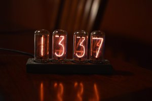
 Gary Marsh
 Frederic L
 Dave Gönner