 Jasper Sikken
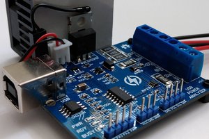
This device is special because the hardware and software is open source, it is Arduino compatible, and it is a cheap tool all hardware designers should have. It works up to 19.8V, 5A and 16W/21W depending wether you choose the smaller or larger heat sink. The load can be set to constant current, constant power, or constant resistance by simply typing it into the Arduino serial monitor. The constant current circuit is implemented in hardware using an opamp, a mosfet, and a current sense resistor. The input for that circuit is made with a 12 bit DAC. The constant power and constant resistance mode is implemented in software. Load voltage and current are measured using a pair of high precision opamps (MCP6072) and the microcontrollers 12 bit ADC. Battery capacity can be measured by loading the battery with constant current and it will simply display the mAh's in the Arduino Serial Monitor. To protect the battery against undervoltage the load is removed when the voltage falls below a configurable threshold. The device can also be used to simply log a voltage or current over time.
Dave Jones from EEvblog discussed my previous revision device in everyone's favorite segment Mailbag. Check it out.
Specifications
- Current set/read range: 0 to 5 A
- Current set/read resolution: 12-bit, 1.22 mA/bit
- Current set/read accuracy : 5% in range 0.1 to 5A
- Current settle time (10-90%): rise 20us, fall 8us typical
- Pulsed current: minimum 156us wide pulse, or 2.9kHz square wave (0 and 5A)
- Voltage read range : 0 to 19.8V
- Voltage read resolution: 12-bit, 4.83 mV/bit
- Voltage read accuracy: 5% in the range 0.15 to 19.8V
- Max power with standard 16W heat sink at 25 degrees Celsius
- Max power with extra large 21W heat sink at 25 degrees Celsius
- MOSFET: BTS133. It has ESD, thermal, overvoltage, overcurrent, and overload protection!
- Microcontroller: STM32F103C8T6 ARM Cortex-M3 (blue pill)
- Power supply: micro USB cable (not included)
- Load connector: 2 pins screw terminal 5.08mm pitch 24-12 AWG, and 4 mm PCB holes for banana plugs
- Net Weight: 80 grams
- Size: 72x54x49mm standard heat sink, 72x54x67mm extra large heat sink
- USB cable is not included

Quick start
- Connect your power source to the plus and minus terminal of electronic load
- Connect USB cable to the computer
- Start Arduino IDE
- Select the COM port (both NL & CR)
- Open Arduino Serial Monitor
- Type any of the commands below
- Every second the voltage, current, power, and capacity are printed to the serial port
Serial Monitor Commands
- Type CC 100 to set a constant current of 100 mA
- Type CP 100 to set a constant power of 100 mW
- Type CR 100 to set a constant resistance of 100 Ohm
- Type pulse 500 5000 500 50 500 2500 500 50 to set repeating pulsed load of 500us@5000mA, 500us@50mA, 500us@2500mA, and 500us@50mA
- Type limit v 1000 to set the undervoltage limit to 1000mV
- Type limit p 15000 to set the power limit to 15W
- Type help for more commands
Storing the data
Arduino Serial Monitor cannot save the serial port data. Well, you can copy what was printed to the screen and store it as a CSV or text file. But I recommend using Realterm because it can store the data in a file and add a timestamp for further processing in other tools, for example in a spreadsheet.
Testing a power supply
Constant voltage power supplies can be tested by applying different loads and see how the voltage is reduced. It may also be used to test a dc-dc converter efficiency under different loads. For example, type cc 100 in the serial monitor and you will see the current being set and the voltage updating at regular interval.
Youtube video with demo of setting the current using R2
And another video where I test a $1.26 1A USB travel adapter
Testing a solar panel
Solar panels generate most power at a certain voltage, the maximum power voltage, Vmp. The Vmp can be found in the IV-curve of a solar panel, which is the current versus...
Read more »
 CentyLab
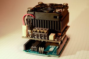
 Stefan Wagner
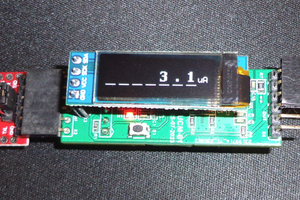
 Alex Fatiuk