 CentyLab
Purchase worldwide Elecrow
Purchase within the US Lectronz


Specification
Tested USB PD3.0 and USB PD+PPS from 3.3V to 20V @ 5A continuous. Actual voltage and current output depend on your charger. This include 12V @ 5A
Please check the recommended charger if you don't already have one.
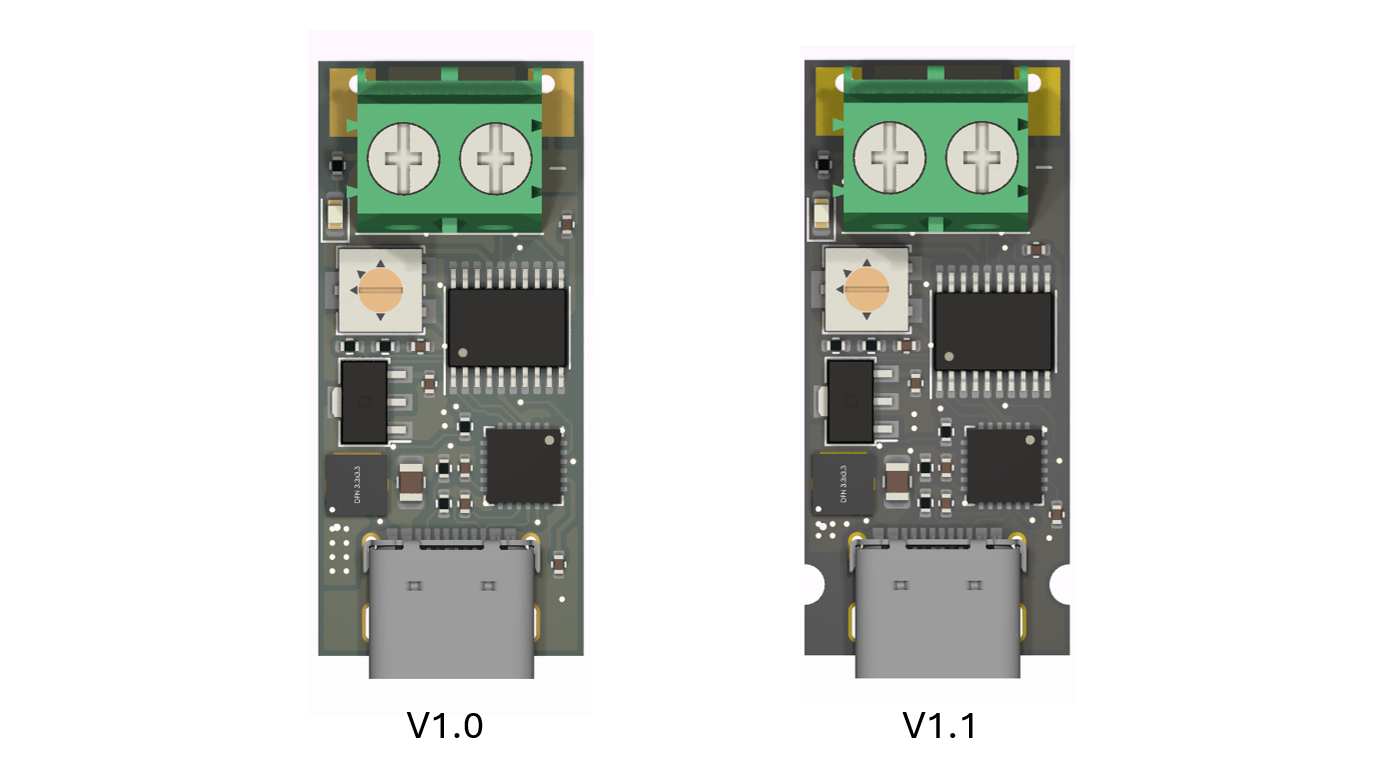
V1.0: Without mounting screw. As of March 2023, all Lectronz stock has been upgraded to better ESD protection.
V1.1: With mounting slot and screws. As of March 2023, all Lectronz stock has been upgraded to better ESD protection.
V2.0: Under testing. Support current limit. Link to project here.
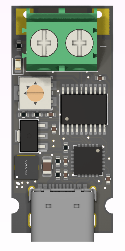
How to use the board
- Default (no jumper): Always able to adjust voltage through potentiometer. Full range of your PPS charger.
- 5V jumper: Request constant 5V
- 9V jumper: Request constant 9V
- 12V jumper: Request constant 12V
- 15V jumper: Request constant 15V
- 20V jumper: Request constant 20V
- Pot jumper: Read the potentiometer at start-up and request this voltage. Voltage is not changeable during normal operation
Theory of operation
The device utilizes the AP33772_CPP library. Using the awesome USB-PD standard, the PPS mode can provide equal or more current than the fixed PDO within its voltage range (3.3V-11V or 3.3V-21V) except for 20V for some chargers. The device will always try to negotiate using the PPS profile first. If the charger is missing PPS capability or the PPS voltage range is under the selected voltage, a fixed PDO will be used.
There is no current limit, you can use up to the rated current on the charger. Higher than spec current draw will cause the charger to reset and re-connect after a couple of seconds. This is a standard safety in USB-PD charger.
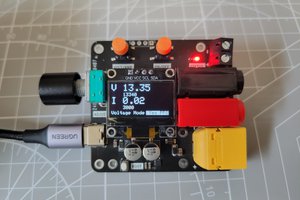
PPS Example
Let us use a UGREEN 140W charger with the given power profile:
- 5V@3A, 9V@3A, 12V@3A, 15V@3A, 20V@5A
- 3.3V - 21V@5A
Since this board has PPS, when turning the potentiometer, you will get the full range starting from 3.3V to 21V. Keep in mind that the power brick tends to give a bit more voltage when there is no load. This is to expect some voltage drop across the cable when the load is attached.
If fixed voltage is selected, for example, fixed 9V. The device will request 9V in PPS mode.
Current limited is built-in to the USB PD 3.1 devices. If the cable is non-e-mark (3A rated), your PPS voltage range is limited based on the load so that the max current draw is only 3A max, preventing the circuit from being over current. Similar to an e-mark cable (5A rated), the current will cap out at 5A and the voltage will stop increasing even if the user tries to crank up the voltage. However, if the load is attached later and the device detects a high spike in voltage, it will go into over-current protection mode, stop the current flow, and restart. These are observed behavior from some UGREEN chargers. PPSTirgger does not directly contribute to charger behavior.
Charger/Cable configuration

Recommended/Tested USB-C Charger
- UGREEN 100W - PPS 3.3 - 21.0 @ 3A
- UGREEN 140W - PPS 3.3 - 21.0 @ 5A
- AOHI Magcube 140W - PPS 3.3 - 21.0 @ 5A
- GKUTW HX65P3 65W - PPS 3.3 - 21 @ 3A
- Anker 737 (GaN Prime 120W) - PPS 3.3 - 11.0 @ 3A
- Anker 737 Power Bank - PPS 3.3 - 21.0 @ 5A
- Anker PowerHouse 521 - PPS 3.3 - 11.0 @ 3A
- ..... too many. Mostly anything that says "PPS" would work
Many Anker charger/power banks do not include PPS capability in their marketing document. However, some devices still support PPS and thus require some testing. UGREEN markets PPS directly in their datasheet.
Dimension

Testing result
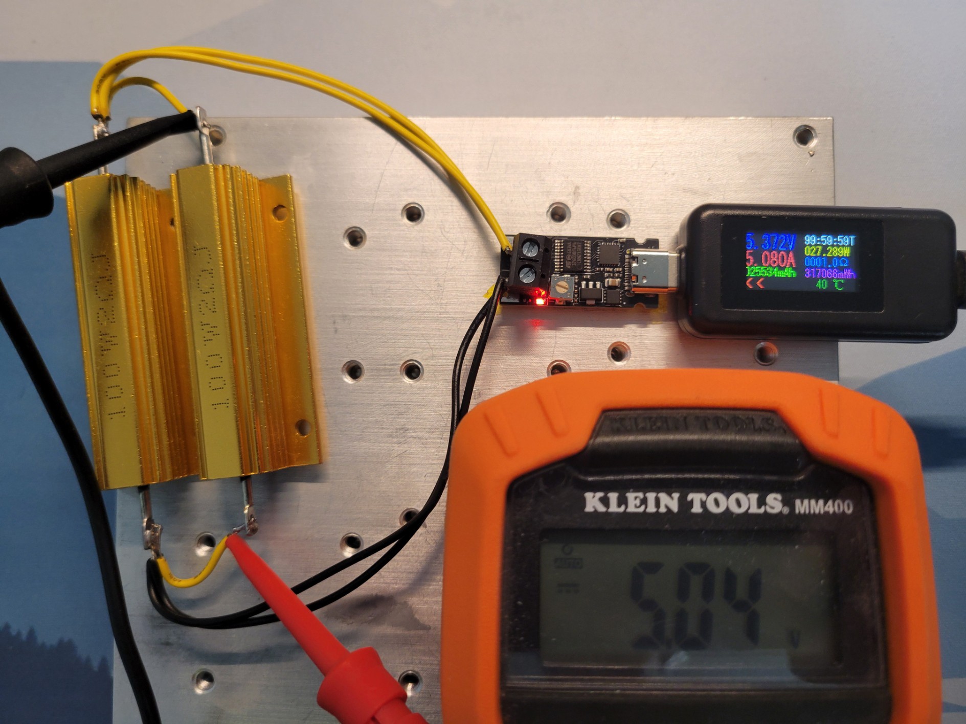
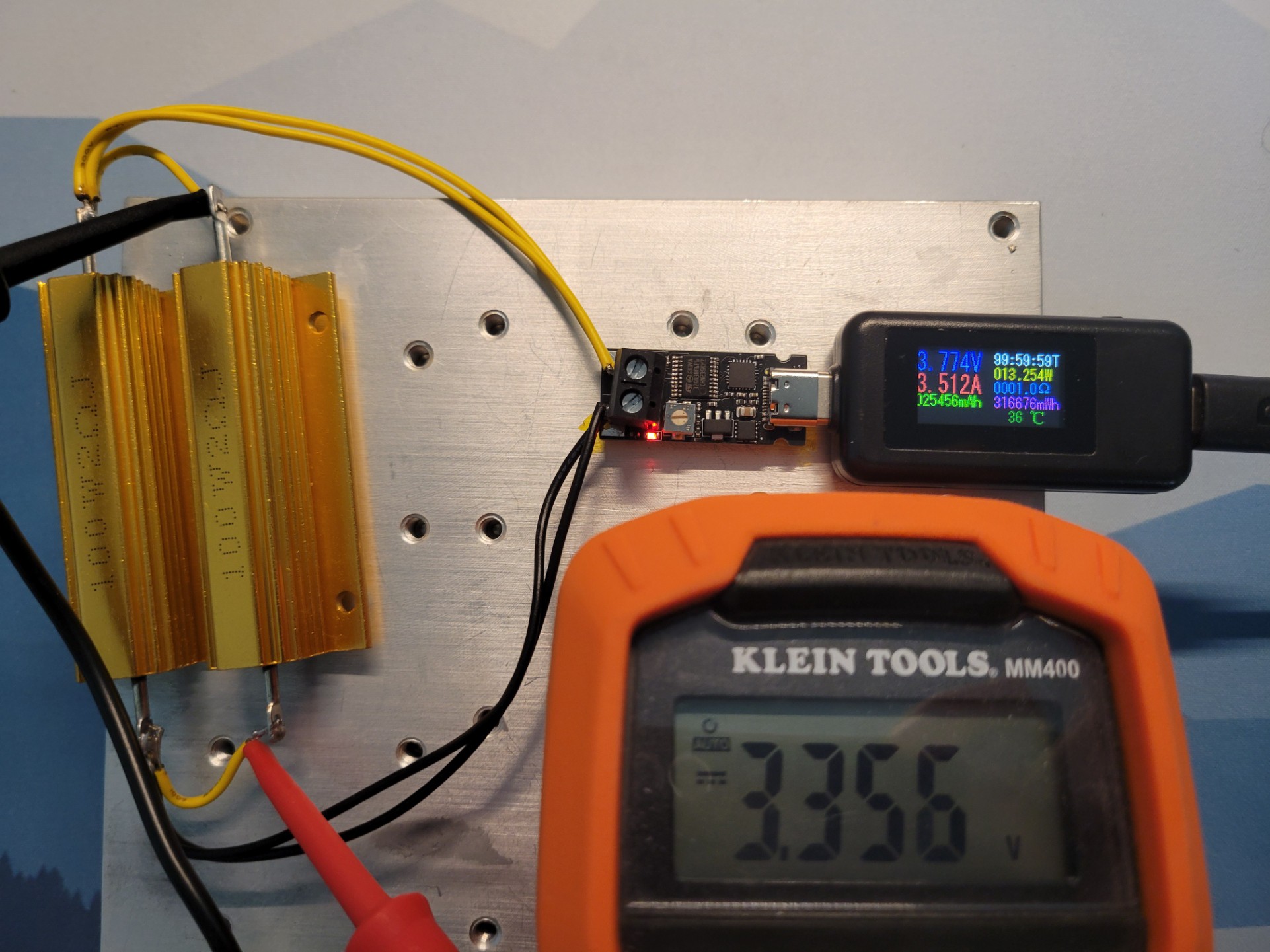
Stress test 5V @ 5A for 4 hours. The board temperature settles below 55C, well within spec for all ICs.
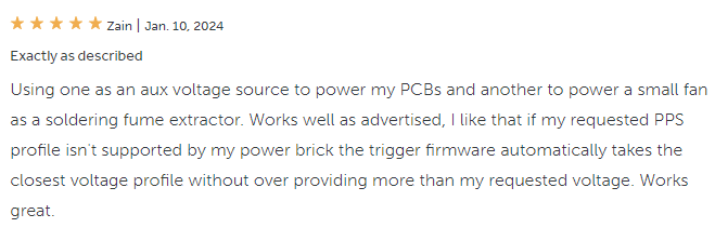
Our first 5 stars review


 Jasper Sikken
 Alex Fatiuk
When you say "Voltage is not changeable during normal operation" do you mean you cannot adjust the PPS voltage when there is a load? Also, this board is amazing, thank you for making it!