Overview
The DPS201 is a PC controlled 0V to 20V and 0A to 1A lab power supply. The entire project consists of the hardware (the DPS201 it self) together with firmware and the PC software PScontroller.
Specs
- Input voltage
9 - 25VDC - Output
0 - 20VDC (max output voltage decreases with input voltage)
0 - 1A - Load regulation
Constant Voltage: Less than 10%
Less than 250uS recovery time for load change of half the rated output current at any constant voltage setting. - Line regulation
Constant Voltage: Less than 0.01%
Constant Current: Less than 2% - Ripple and noise
Constant Voltage: Less than 10mV(RMS)
Constant Current: Less than 10mA(RMS) - Programming resolution
Constant Voltage: 100mV
Constant Current: 10mA - Metering resolution
Constant Voltage: 100mV
Constant Current: 10mA - Programming accuracy
Constant Voltage: 1%
Constant Current: 1% - Metering accuracy
Constant Voltage: 1%
Constant Current: 1%
History
The DPS201 power supply is a product of weekend tinkering after reading one of late Jim William's excellent app notes, titled High Efficiency Linear Regulators. There he explains how one can design a ultra low dropout regulator using low R_DS(on) N-channel MOSFET and a switching pre-regulator which ensures the low dropout. Our design is based on exactly this principle, using LM2596 switching regulator as pre-regulator and a simple LM324-based linear regulator. This is a very stable configuration and the efficiency is high so that no heat sink is required. A lack of heat sink is essential to make the power supply small and cheap.
Theory of operation: hardware
A simplified block diagram is displayed below. Note that the block diagram only shows the voltage feedback loop, a current feedback loop is of course also present in the circuit.
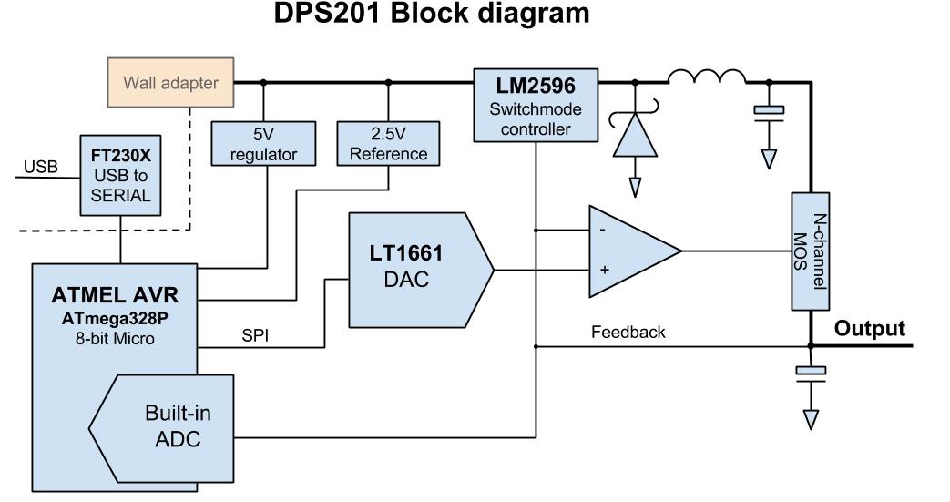
The voltage control and current limiting is handled by OPamps. In this case a pair of LM324 together with a precision reference (TL431) and precision resistors where needed.
The PC interface and control of the supply is fairly simple, the Atmel ATmega328P, a 8-bit micro controller, handles all logic. The interface to the analog circuitry is via LTC1661, a 10-Bit A-to-D converter which feeds the set voltage directly into the error amplifiers. The micro has a built in 10-bit D-to-A converter which is used to measure the output voltage and current. The USB signal from the PC is fed through FT230X, a USB to serial converter, which is opto-isolated from the main circuitry. Note that galvanic isolation is crucial for proper lab supply and even though our design is simple and essentially targeted at hobbyists, it is still much more useful to have a supply that is entirely isolated from earth. In our case, galvanic isolation is ensured by the AC to DC wall adapter that supplies the power to the supply and the optocouplers that electrically isolate the PC ground from the DPS201 signal ground.
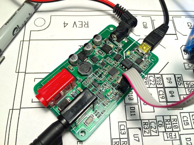
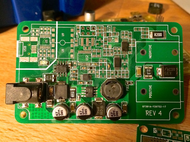
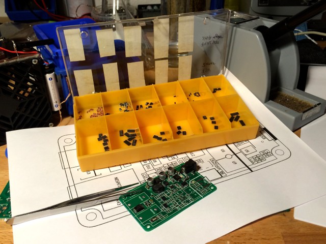
One key goal of the project was to make the PSU as small as possible. This meant using SSOP and 0805 surface mount packages. Heat dissipation is very important in a small designs so the switch mode converter had to be efficient, especially at large loads. We managed to bring the PCB size down to 8 x 8 cm where most space is taken up by connectors. We decided to use proper banana jacks for output connectors to ease the use of the supply.
Theory of operation: software
The DPS201 is controlled by a local python based web server. The web server connects to the DPS201 via USB and exposes it's functionality through an API.
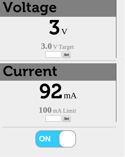
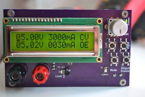
A simple browser UI is provided (seen above) while more complex tasks can be performed by directly calling the API. The web server runs on Linux, Mac and Windows.
 Elia
Elia
 The Big One
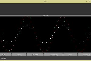
 BunneyDude
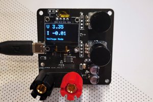
 CentyLab