Close
0%
0%

Serial Port SDR

Transmit radio signals using just a serial port? You bet!

Public Chat
Similar projects worth following
Common USB-to-UART bridges are capable of handling 2Mbps or more of throughput - enough to reach medium-wave (AM broadcast band) frequencies directly. And, unlike the true serial ports of yesteryear, the slew rate of TTL-level ports is not controlled: they have very fast edges which generate a rich set of harmonics up the bands. What mischief can be had with this? Let's find out.

Audio Transmission

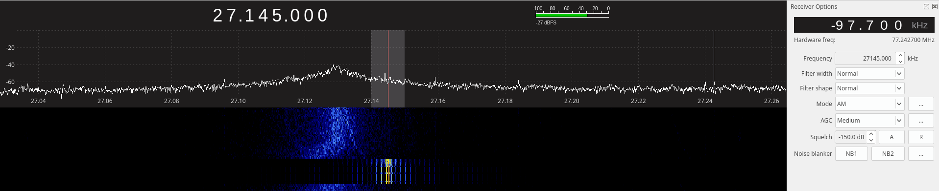
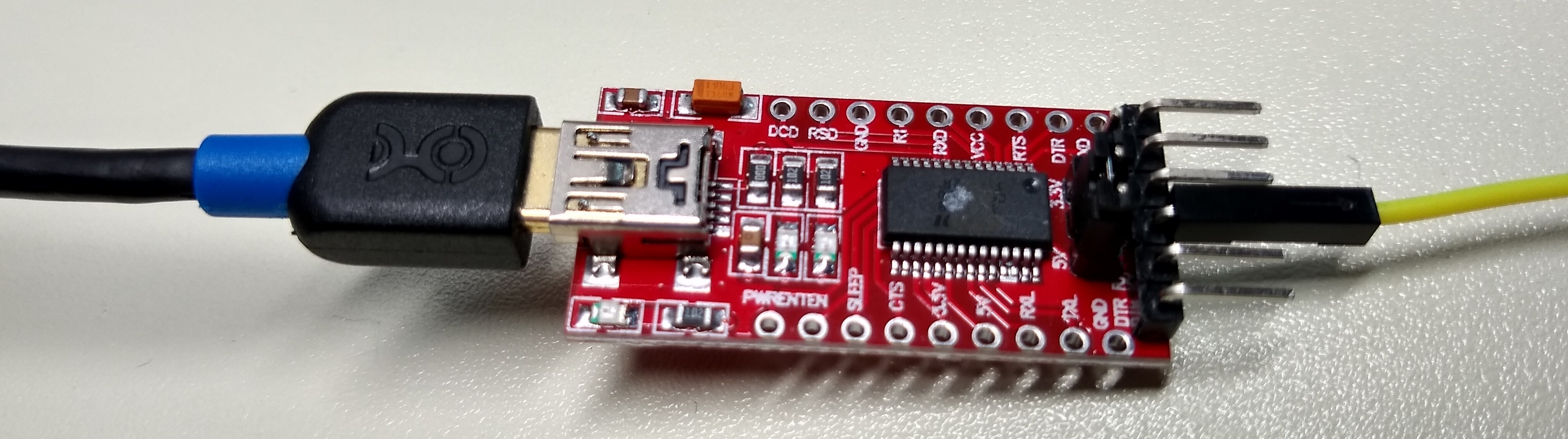
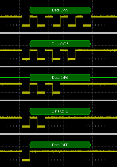
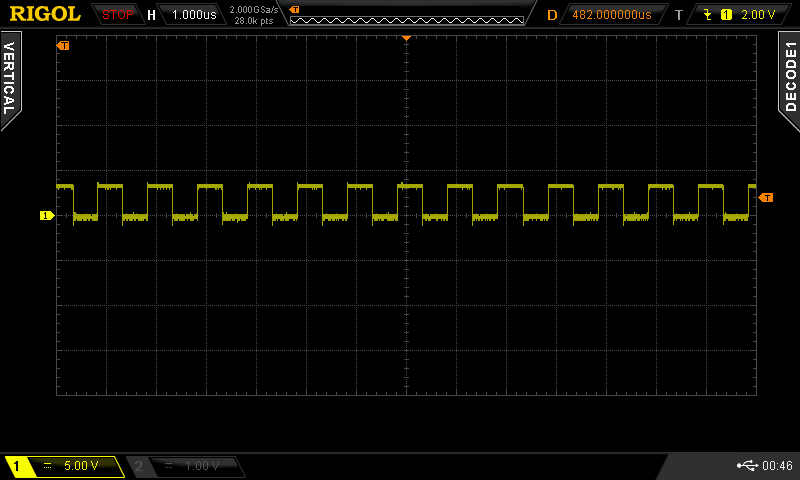
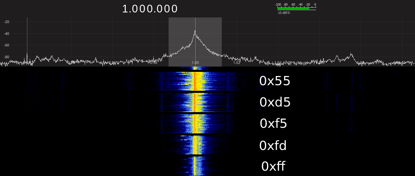
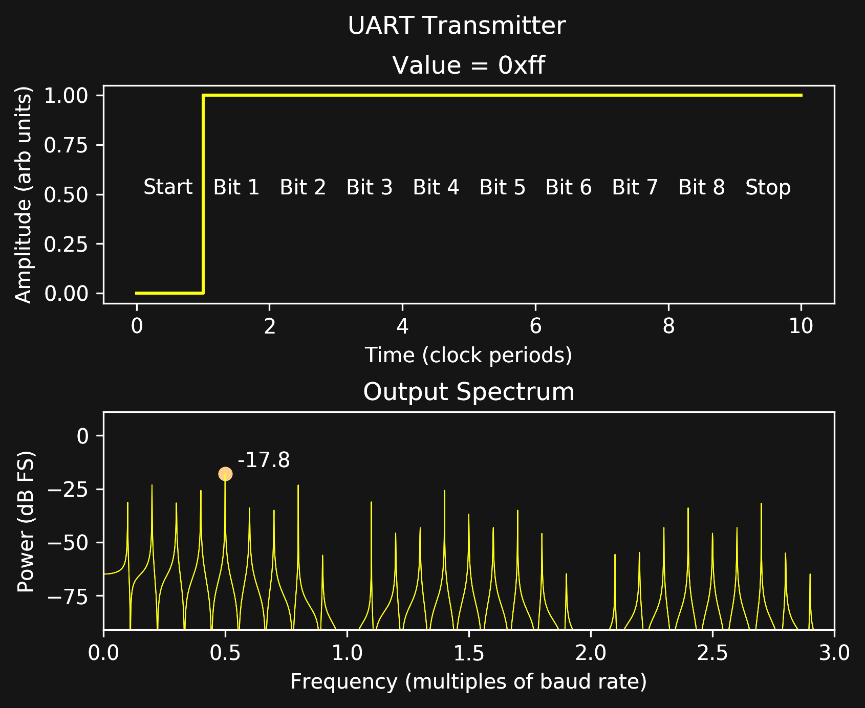
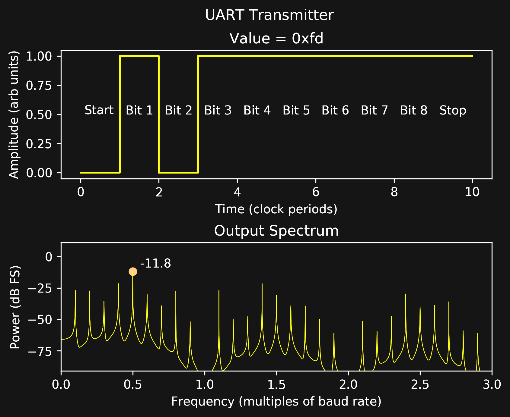
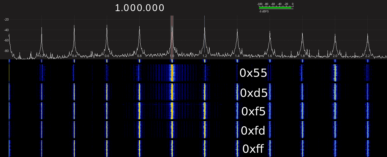
Here is the best audio transmission result so far, using an FT232RL serial port to transmit a signal on 1MHz.  This signal was received with an up-converted RTL-SDR, but it works just as well on a normal AM radio.  The signal is modulated simply by sending the appropriate sequence of bytes through the port.  It uses a 5-level delta-sigma modulator as described in the build log.

The FT232RL transmits a cleaner signal than some other parts, such as the CP2102N, which I suspect is intentionally using a spread-spectrum clock to reduce emissions while staying within the stability limits imposed by serial port framing.  Or, maybe they simply use a just-good-enough oscillator.

Controlling an RC Truck

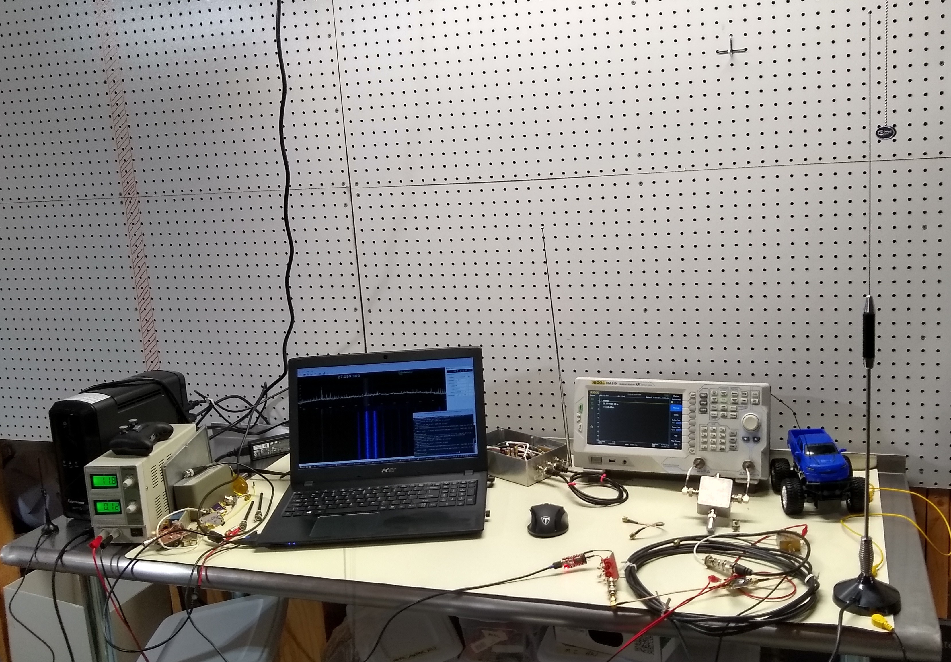
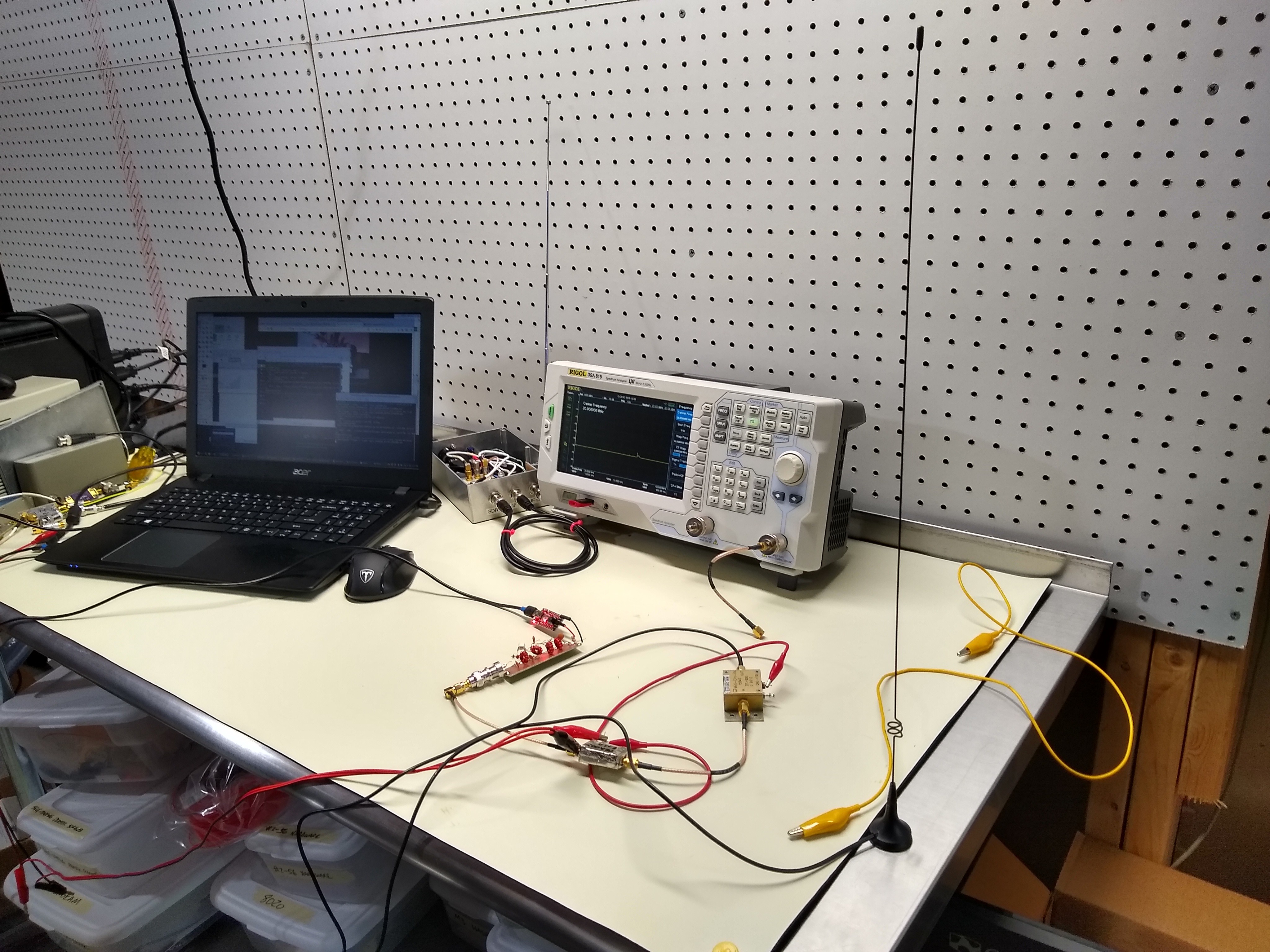
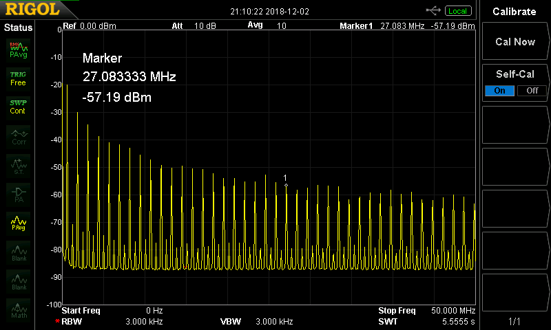
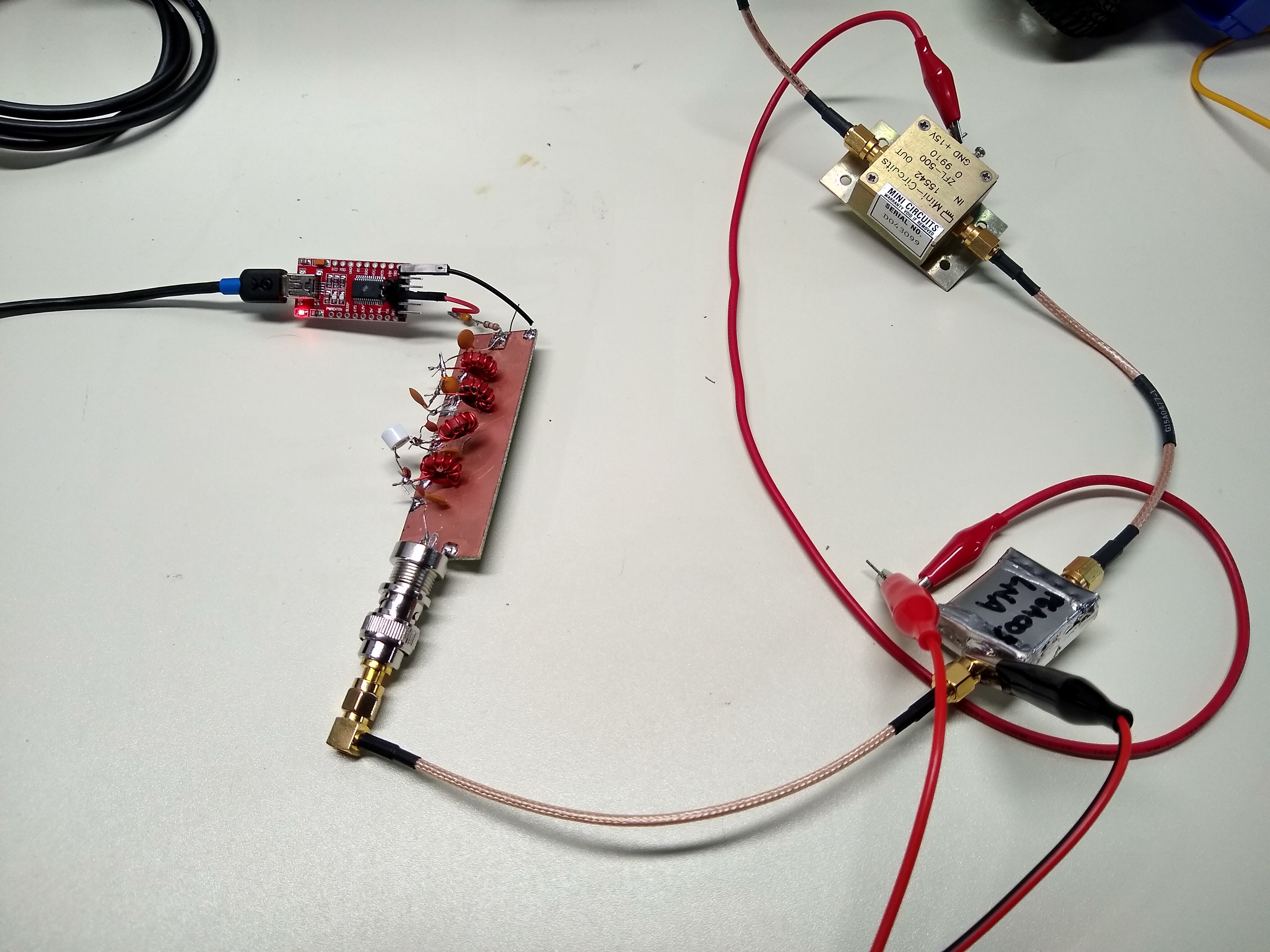
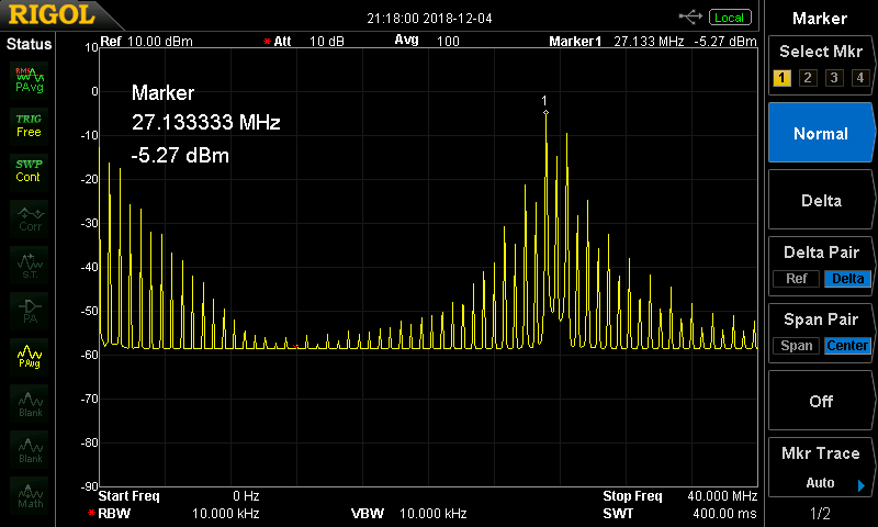
I have also been able to control a 27MHz toy with signals transmitted by a serial port, which you can check out in this video:

The code to do this and more is being developed on GitHub; you can grab the code there and experiment for yourself.

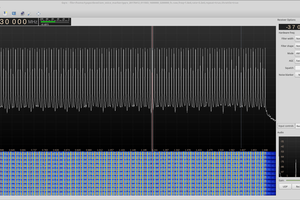
The techniques used are detailed in a build log, and here's a video of three different modulation techniques.  The CP2102 is naturally noisier than the FT232RL above, but you can still tell the difference between the methods.

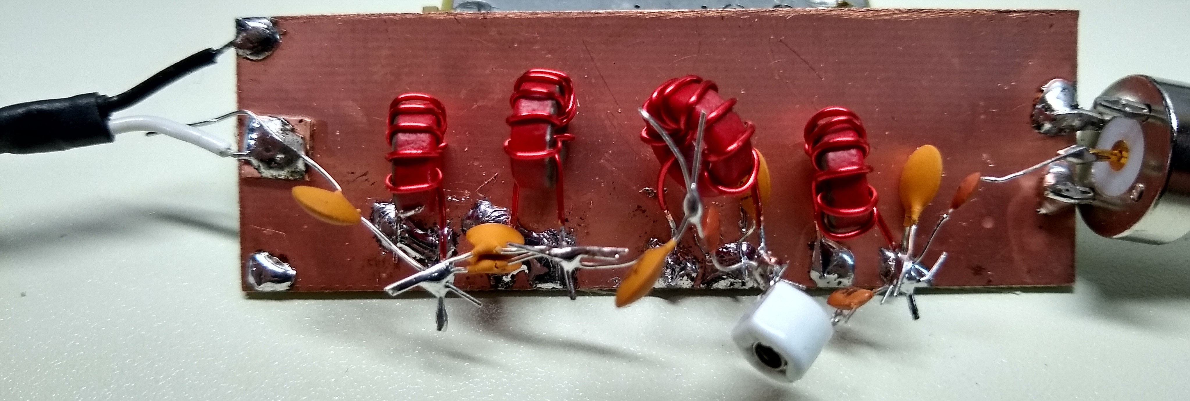
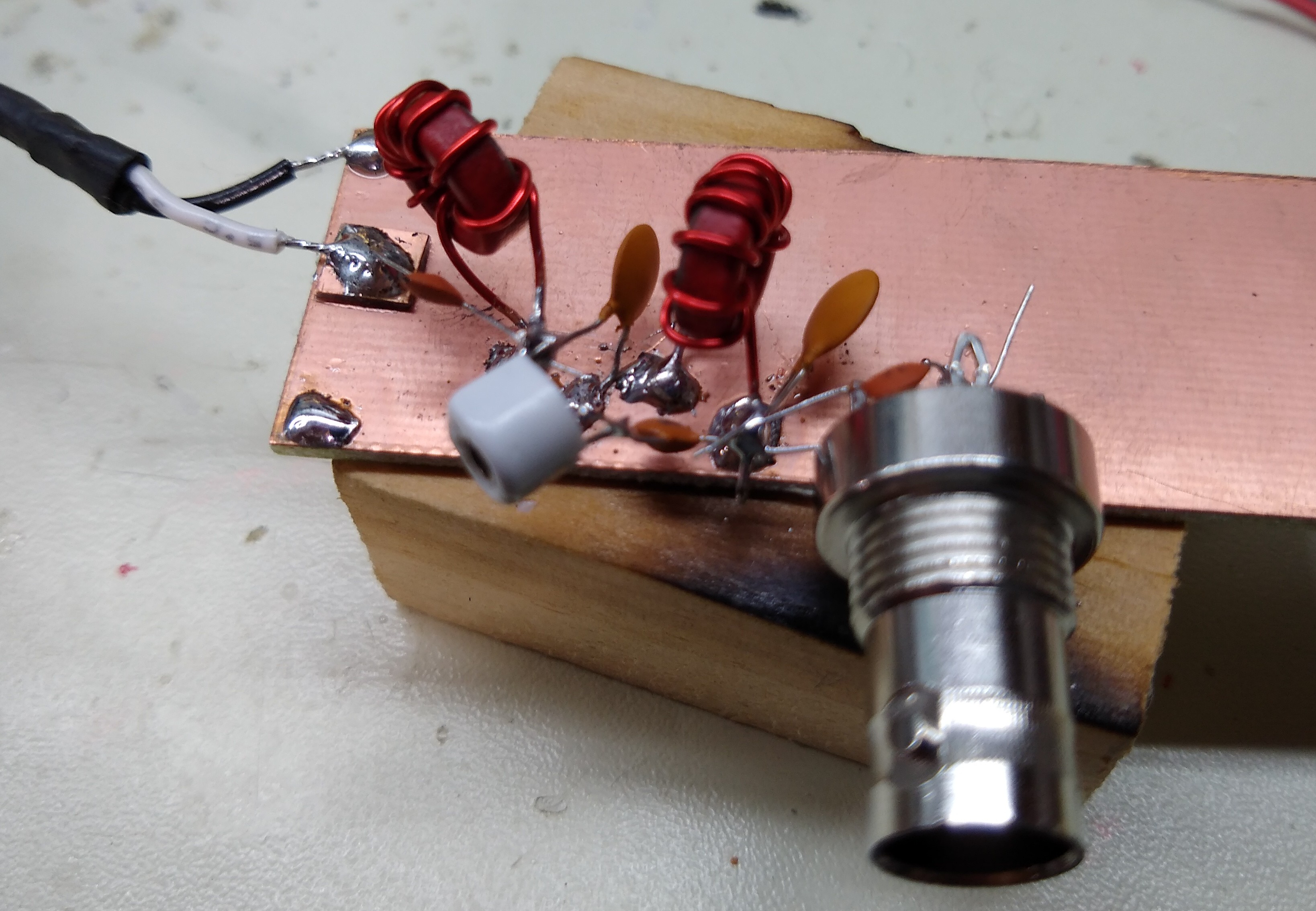
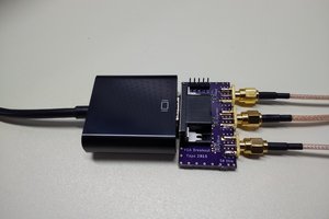
And here is the transmitter:

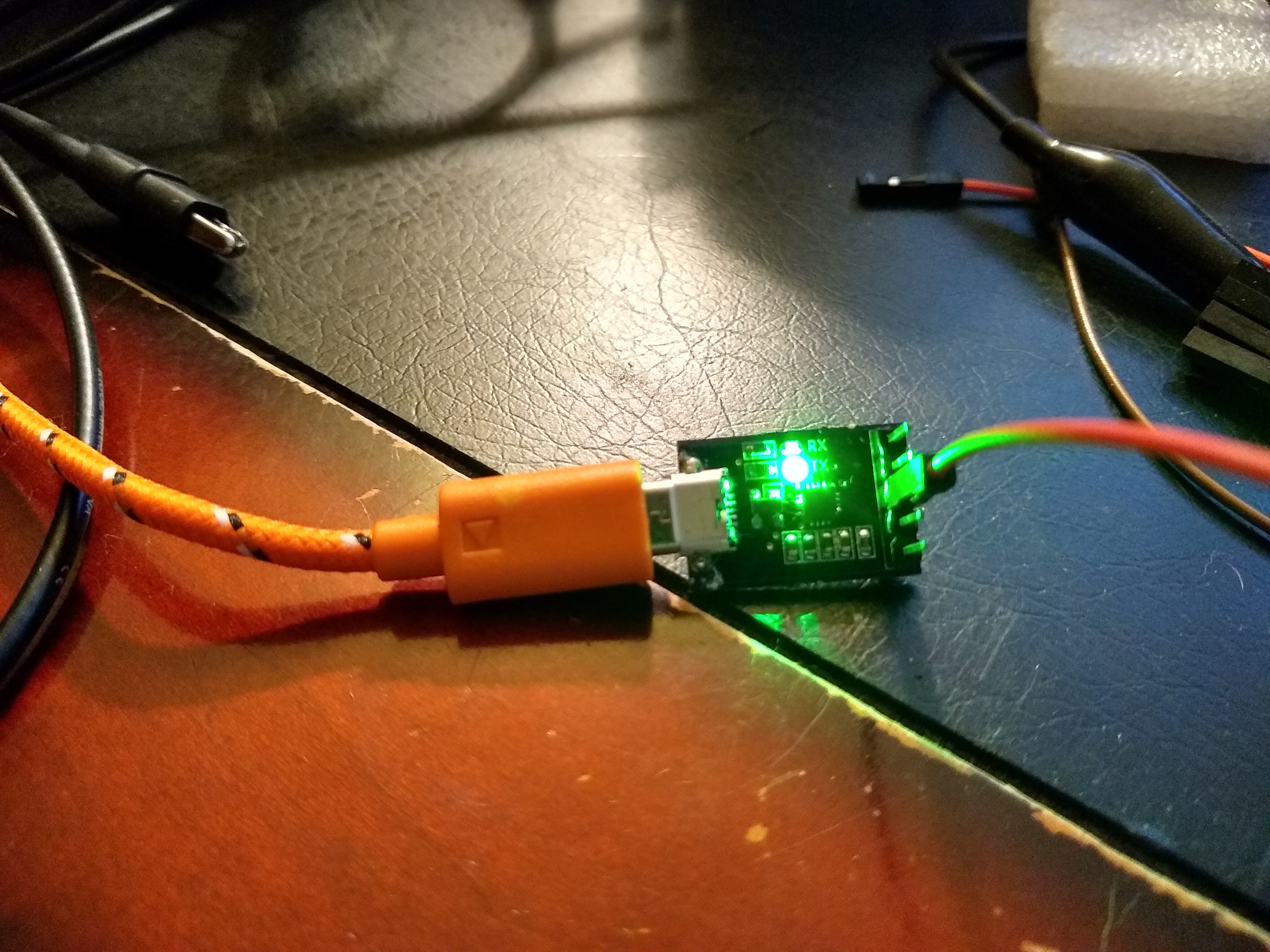
It sounds pretty good, considering. It turns out, you can also use this method to output baseband audio directly from a serial port. Check the build logs for more details as I document my experiments.

More Details

Upcoming Logs

  • Baseband Audio: Your serial port is a soundcard
  • Receiving (?)

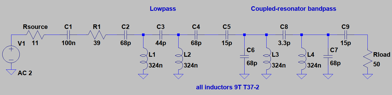
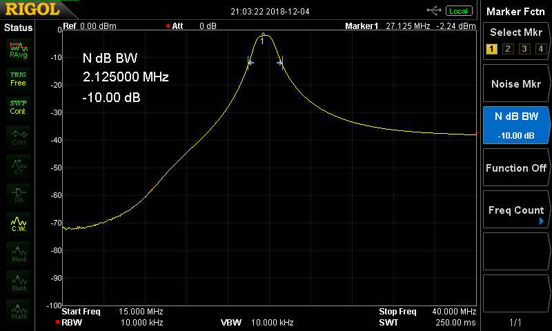
I should mention that the RF output from this project is loaded with spurs and harmonics, and wouldn't be suitable for any real purpose without some serious bandpass filtering (at least).

DISCLAIMER: It should go without saying that you should never transmit on any frequencies or at any power levels for which you are not authorized by the local governing body, but I guess I just said it anyway.

  • Speed Improvements

    Ted Yapo01/01/2019 at 15:14 1 comment

    Just a quick note about the recent changes in the GitHub code. I added numba (a JIT parallelizing compiler) support to the code. I see around a 10x improvement in execution speed with the new code, although YMMV.

    This improvement probably opens the path for live streaming audio transmission, if that's an interesting thing for anyone. The code does not support this at the moment.

  • Again, with a real antenna

    Ted Yapo12/05/2018 at 18:11 0 comments

    I used a return-loss bridge to test the dual-band antenna I had started using for the 27MHz RC experiments, and it was very bad.  Luckily I had an old CB antenna around, which is made for 27MHz: it showed a 21dB return loss, so the antenna is quite good.  Using this antenna, I get about 3 feet of range with just the serial port and the LC filter network (no amps).

    That's it at the right side of the photo.  It has a magnetic base which attaches firmly to the steel table as a nice ground plane.  If I add the two amplifiers as before, I can control it all the way to the end of the lab - at least 20 feet.  I don't know how much further it would actually work, but that's good enough for me :-)

    Replicating the Experiment

    I also wanted to document exactly what I did to make this work, so anyone who wanted to replicate the experiment wouldn't have to stumble around like I did at first.  The first trick was finding the right RC toy.  I found the cheapest ones they had - not only to save cash, but because cheap ones are likely to have wide (non-selective) receivers, so the transmit frequency doesn't have to be exact.  A good clue about the one I selected was the "27 MHz" sticker on the box. 

    They make different frequencies so you can race.  In the case of this model, there were "27 MHz" and "49 MHz" versions on the shelf.  This is much better than if they had "27.145MHz" vs "27.195MHz" or similar frequencies both in the 27MHz RC band - in that case, the receivers would have to respond only to a narrow band of frequencies which you might not hit with harmonics of the allowed serial port baud rates.

    Signal Capture

    Here are the GQRX settings I used to capture the signal.  I used an upconverter I built since I was also looking at the lower harmonics and fundamental, but for 27MHz you could use an RTL-SDR dongle directly.

    It's just AM demodulation with the normal filter width and shape.  The file gets saved with 48kHz sampling and two channels, but this doesn't matter because the transmitter program resamples to 11025 Hz mono by default.

    Signal Replay

    To replay the signal, I used code from the GitHub repo - it's the same command used to transmit AM audio signals, except this time the signal is the one we recorded from the RC transmitter.  I used this command line to send the RF signal from the serial port:

    ./serial_sdr_tx.py -p /dev/ttyUSB0 -f 631e3 -l -m pdm recorded_codes.wav

    This sends the output to the port on ttyUSB0 at a fundamental frequency of 631kHz using the 'pdm' modulation method.  In my early tests, I found the pdm method to work best, but this may vary with a number of factors.  I should revisit this at some point.  I found the 631kHz frequency by observing the GQRX display while transmitting unmodulated square waves with the other code in the GitHub repo:

    ./square_wave.py /dev/ttyUSB0 631e3

    I saw that this particular frequency had a harmonic very close to 27.145 MHz (666kHz was a close second).  Once I had captured some codes, it was easy to verify that 631kHz worked best.

    Using just a jumper wire as an antenna, the toy truck has to be very close to the transmitter.  Having the antennas touching (even through the insulation) will let you know right away if it's working; then you can experiment with longer ranges.

    Up Next

    I keep talking about audio output from a serial port; I really need to write it up :-)

    I have also made some progress on receiving RF with just a serial port.  I was lucky enough to catch Dominic Spill's talk at Supercon about "Ridiculous Radios" - I don't think it's on youtube yet, or I'd post a link.  Anyway, he covered some interesting radio receivers using digital circuits.  When I get a chance to watch it again, I'll check for clues that might help.

    The additional problem I have here is that I can't sample the RX line without a start bit, and that's not guaranteed...

    Read more »

  • Moar Range!

    Ted Yapo12/05/2018 at 02:51 2 comments

    I added a filter, a cascade of two amplifiers and a half-decent antenna, and achieved around a 10-foot range controlling the 27MHz toy truck with a FT232RL serial port as a transmitter.  The experiment also proves that it's the 43rd harmonic (and perhaps a few neighbors) that's controlling the truck, and not the fundamental overloading the receiver.

    The antenna is on the right.  It's really a lousy dual-band 2m/70cm amateur band antenna, but the toy truck doesn't know this. It's probably better than the random length of wire I had been using, and it had the right connector already :-)

    You recall from last time that I'm using the 43rd harmonic of a 631kHz signal, because out of the limited range of baud rates the FT232RL can manage, this comes the closest to the 27.145MHz RC frequency.  The harmonics are pretty strong, but even a perfect square wave will have the 43rd harmonic down 33dB from the fundamental (20log10(1/43)).  In this case, it's more like -37dB.  (Note that there's a 10dB attenuator in the signal path for this measurement; the absolute numbers are 10dB higher.)

    I wanted to knock down the strong lower frequencies and leave just those near 27MHz.  For a filter, I combined a low-pass design with a coupled resonator bandpass, shown here constructed ugly-style on a scrap of copper clad.

    The schematic is shown with the nominal component values, although the actual circuit contains a lot of parasitics, and the inductors are probably off a bit from the estimated values.  I added a 3-10pF trimmer in series with the 3.3pF coupling cap, and tuned to get a narrow, flat passband.  I assumed the FT232RL had around 11-ohms of output impedance, so added a 39-ohm resistor to make the source impedance 50 ohms.

    The inductors are all 9 turns of 22 or 24 Ga wire on T37-2 toroids.  They calculate out to 324nH, but I suspect from the performance of the circuit that they're closer to 400nH including the parasitics from the long leads and my winding style.  The filter response measures out nicely on the spectrum analyzer after tweaking the trimmer and compressing the coil turns a bit:

    As you can see, the response is 10dB down at a bandwidth of around 2 MHz.  That picks out just a few harmonics around 27MHz, although they are pretty weak at this point:

    To boost these few frequencies to usable levels, I added a cascade of two amplifiers, first a PGA-103 followed by a Mini-circuits ZFL-500.  I used these two because they were the first I found in the box that gave enough gain together.  The PGA-103 isn't spec'd down to 27 MHz (datasheet says 50), but it seems to work fine.  I did the right thing and used the lower-noise amp first, even though it has a higher P1dB in this case :-) 

    Together, they give a nice 37dB boost to the 27MHz signal:

    But, this gain does resurrect some of the fundamental and low harmonics, as seen here in a wider span:

    The fundamental is still down 10dB from the 27MHz line, so I'm fairly confident that's not controlling the truck.  After the whole chain, the 27MHz signal is at around -5dBm, or approximately 140uW.  It's a flea's burp, but it does control the truck out to about 10 feet.

    Overall, this seems like a lot of work, but I really wanted to see if it was that 43rd harmonic at work or not.  I'm confident that this isn't just a case of receiver overload, and that the serial-port SDR is indeed transmitting a usable signal on 27MHz.

    Up Next

    You know you want to use your serial port as another audio output.

    I'm stalling on the receive side, hoping for some serious inspiration :-)

  • Controlling a 27MHz RC Truck

    Ted Yapo12/04/2018 at 02:51 4 comments

    I found a 27 MHz RC truck at Walmart for $10 - so now, I've blown my budget for this project.  But, at least, I did get the serial port SDR to control it :-) Check out the video here:

    It works because the fast edges of the waveform on the TX line create strong harmonics.  In this case, I used an FT232RL adapter because the clock is more stable than other bridges, and this creates cleaner harmonics.  Here's the adapter with a wire connected as an antenna:

    This adapter has a 5/3.3 jumper to set the output signal level.  Setting it to 5V gives an extra 3.6dB of output :-)

    As shown in the video, the codes are captured as an audio file using GQRX, then modulated and transmitted on the serial port using my python code.

    I set the fundamental frequency to 631kHz, because out of the limited baud rates the FT232RL is capable of, this one puts a harmonic closest to 27.145 MHz, the RC truck's transmitter frequency.  You can see the harmonics on this spectrum analyzer plot:

    That's the 43rd harmonic, and it's actually -47dBm, because there's a 10dB attenuator in-line to protect the analyzer.  That signal is pretty weak, so the truck has to be very close to the transmitter.

    It's also very possible that the truck is responding to any of the other harmonics (or multiple ones) since it is so close to the transmitter.  This could be overloading the receiver, although the remote codes still are received well enough to operate the truck.  It controls it from a short distance, at least, so I'm counting that as a success :-)

    To figure out exactly what's happening, I'm experimenting with a bandpass filter, which you can see here:

    The filter will knock out the fundamental and low harmonics, leaving just those near 27 MHz.  So far, the response looks promising:

    I'll amplify the filtered signal and see how well it works for controlling the truck.  Plenty more details and results in the next log.

  • Fun with Harmonics: VHF from a Serial Port

    Ted Yapo11/30/2018 at 18:15 0 comments

    I measured the edge rates on the TTL output of some of these USB-UART bridges to be under 2ns.  This generates some strong frequency harmonics, which you can see here in the 67th harmonic of a 1MHz square wave output by an FT232RL driven by the square_wave.py code from the GitHub repo. Yes, that's a 67 MHz signal from a serial port.

    You can see three strong spurs surrounding the harmonic - these are themselves harmonics of the strong sub-harmonic spurs created by the modulation technique.  The other thing that is apparent is the instability of the signal.  You'd normally call this jitter since it's a ostensibly a digital device we're dealing with, but the term phase noise is equally applicable in this case.  The problem with harmonics is that they multiply the phase noise just as they multiply the frequency - this signal has 67x the phase noise of the 1MHz fundamental.  It's possible to receive AM audio on this carrier, but the receiving width of the demodulator has to be increased to include the larger bandwidth of the "wandering" signal.  You can definitely hear it, though!

    The other problem with harmonics is that they can be substantially weaker than the fundamental.  The output here is a square wave, and for an ideal square wave, the amplitude of the Nth fundamental is proportional to 1/N.  So, for this 67th fundamental, the amplitude is 1/67th, or down 36.5 dB.  Using one of these harmonics in a meaningful way without creating serious interference on other frequencies would be very difficult.  But they might work for a stunt-type hack :-)

    I've looked at higher harmonics, and they're "usable" into the upper VHF range.  I received an AM transmission at 151 MHz, for instance, but the quality was very poor.  I am very interested in spoofing some RF remote device with this system.  433 and 315 MHz are simply out of reach - I tried.  The signals are too weak and too unstable.  I think the best bet is a toy remote on 27 or maybe 49 MHz.  I'll keep an eye out for super-cheap 27 MHz remote-controlled cars; they used to involve super-regenerative receivers which weren't very selective, although I don't know what they use these days.

    Other Bridges

    The FT232RL shown above is the best one I've tested in terms of frequency stability.  Contrast the image above with this one showing the output from a CP2102N again at the same 67th harmonic of a 1 MHz carrier:

    The spectrum is amazingly wide - I'm not sure how the chip is generating its frequencies, but looking at the harmonics shows the "stability" is very poor.  I wonder if this is an intentional move to reduce the emissions profile of the device.  The striated spectrum would indicate some sort of digital spectrum-spreading technique is being used.  If so, it works, because the resulting harmonic is not suitable for transmitting audio or data.  However, the small amount of jitter present in the fundamental at 1 MHz is low enough to avoid framing errors in serial data transmission, which only needs to be accurate to a few percent.  It looks like a clever design from Silicon Labs.

    Interestingly, this chip is otherwise pretty useful for transmitting on the fundamental frequency, where the small amount of jitter doesn't affect the communication.  If you step up to version 4.19 of the linux kernel, you can drive the part to 3Mbps.  In older versions, it was limited to 2Mbps.  I suspect it can go even higher, since I was able to re-program the limit to 4Mbps on a CP2102N here using the Silicon Labs software:

    I don't know if this works yet, since I have to patch the limit in the kernel driver code and re-compile to test it.

    Frequency Agility

    ... Read more »

  • Multiple Modulation Methods

    Ted Yapo11/28/2018 at 20:13 0 comments

    So far, I've experimented with three methods for modulating audio onto RF output from the serial port.  They're all pretty simple, and all cause a ton of spurious emissions up and down the band, but are interesting to play with.  The first method uses the five selected bit sequences to create a type of pulse-density modulation:

    In a normal pulse-density modulation scheme, like the output of a class-D amplifier or the 1-bit delta-sigma DAC inside your expensive CD player, the high frequencies of the pulses are filtered out and you are left with a faithful representation of the input signal.  In this case, the high frequencies of the pulses are used as an RF carrier.

    As shown in the figure above, the simplest way to modulate a signal onto the fundamental frequency is to sample the audio waveform and quantize the signal level to one of the five bit patterns previously discussed.  High levels in the signal result in a higher density of pulses, while lower levels create fewer pulses.  The AM receiver then reconstructs this into a representation of the audio signal.

    Here are the bit sequences again:

    # 0xff -_---------
    # 0xfd -_-_-------
    # 0xf5 -_-_-_-----
    # 0xd5 -_-_-_-_---
    # 0x55 -_-_-_-_-_-
    CODES = [0xff, 0xfd, 0xf5, 0xd5, 0x55]
    LEVELS = [1, 2, 3, 4, 5]

    given these, the python code to create the serial data stream is easy - we simply quantize to five levels and choose the appropriate character to output for each sample:

    def pdm(data):
        """Modulate using character-based pulse density modulation."""
        chars = []
        err = 0
        for val in data:
            err = 2 + 2*val
            idx = max(0, min(4, int(err)))
            code = CODES[idx]
            chars.append(code)
        return chars
     

    The result is a quantization to 2.32 bits since there are 5 levels [log2(5) ~ 2.32].  A 2.32 bit DAC has around 14 dB SNR, so we shouldn't expect too much from this scheme.  You can listen to the result as received on an upconverted RTL-SDR dongle with GQRX here:

    As expected, the results aren't very good, but the signal is recognizable.  If you zoom out on the receiver, you can see all of the spurious emissions created by this method (see below).  Luckily, they are fairly widely separated from the fundamental (at 1MHz in this case), so could be removed with a bandpass filter if one really wanted to use this method.

    1-Bit Delta-Sigma Modulation

    I mentioned 1-bit DACs above.  If you haven't seen them before, you'd think that a 1-bit DAC would be pretty useless, resulting in an abysmal 6dB of SNR.  The trick to making a 1-bit DAC work is oversampling plus feedback.  As shown in the python code below, you simply need to compare the input value to a threshold - if above, a "1" is output, and if below, a "0" is omitted.  After each value is quantized this way, the error is saved and added to the next sample.  This method is known as a delta-sigma converter.

    In this case, a '1' is transformed into a character of value 0x55, while a "0" results in 0xff.  These two characters represent the largest and smallest carrier magnitude, respectively.

    def delta_sigma_1bit(data):
        """Modulate using 1-bit delta-sigma modulation."""
        chars = []
        err = 0
        for val in data:
            err += 2 + 2*val
            if err > 4:
                err -= 4
                chars.append(0x55)
            else:
                chars.append(0xff)
        return chars
    

    The way this scheme achieves better than a 6dB SNR is by oversampling.  In the case...

    Read more »

  • RF from the TX Line

    Ted Yapo11/28/2018 at 02:14 0 comments

    The idea for this project stems from the fact that certain characters sent across a UART serial line combine with the start and stop bits to produce bursts of a square wave at half the baud rate.

    These sequences each emit different power at the fundamental frequency (1/2 of the baud rate). In fact, a sequence of 0x55 characters sent across a UART serial line produces a continuous square wave at this frequency - the stop and start bits of subsequent characters are sent with no intervening space. Shown below was an example at 19.2k, producing a 9600Hz square wave.  If we crank the baud rate high enough, we can use this to transmit RF signals.  The square waves form TTL-level USB-UART bridges also have strong harmonics with which we can reach higher frequencies.

    The five different bit patterns each produce their own level of the fundamental frequency and sub-harmonics.  You can see the power differences in this capture from GQRX, using a baud rate of 2000000, for an output fundamental at 1 MHz.  Each bit pattern was sent continuously for 1 second, with a short space in between.

    As expected, the longer patterns have more power.  You might expect the 0x55 pattern to bet detected with an AM receiver with an equivalent of around 5x that of the 0xff pattern (5 cycles vs 1 cycle).  This 5x amplitude is 25x the power, or around +14dB.  This is exactly what you observe in GQRX for the received signal.

    Simulating the output spectra using a continuous Fourier transform for the piecewise-linear signal waveforms also predicts this difference.  Here are the bit patterns, along with their respective spectra:


    You can see from the annotated power levels that the difference in fundamental power between the 0xff and 0x55 patterns is estimated to be 13.9dB, right where we would intuitively expect it.

    For our purposes, we'll ignore the sub-harmonics and concentrate on the fundamental and higher harmonics.  Of course, this is just an experiment.  If you really wanted to transmit anything with this project, you'd need to clean up the emissions by filtering and make sure you're operating in a band and at a power that you're legally authorized to use.

    Unfortunately, there does not appear to be a way to easily send a zero-level signal on the fundamental without losing accurate timing of the samples.  You can send a break "character" on the serial line, but this has two problems - first, it is not guaranteed to be an exact multiple of the character time, which makes it very difficult to keep an accurate sampling rate.  Also, the break is an out-of-band signal from the software perspective, so you can't have an array of bytes with break "characters" intermixed.  This slows streaming of data to the UART.  So, we are forced to settle for using 0xff as the "carrier off" pattern, accepting only 14dB of dynamic range in the RF signal (but we can use some tricks to achieve more range in the demodulated audio!).

    You can also see from the plots that a lot of sub-harmonics are produced for all patterns except 0x55, which is a continuous square wave.  In this case, only odd harmonics are generated.  If we zoom out in GQRX, we can observe the same thing experimentally:

    You can see how the sub-harmonics really drop off with the 0x55 pattern.

    Up Next

    How do we use these bit patterns to generate an amplitude modulated radio signal?  Or at least a signal that can be received by an AM detector?

View all 7 project logs

Enjoy this project?

Share

Discussions

Josh Lloyd wrote 04/15/2019 at 02:52 point

Very cool project, Ted. Enjoyed the read and the performance you've achieved both with audio and seeing that truck work is encouraging for a cheap SDR transmitter. I must add, all these spurious harmonics must be violating some sort of RF law for you, right? Perhaps a tunable bandpass is in order in an upcoming log ;-)

  Are you sure? yes | no

Ted Yapo wrote 04/15/2019 at 10:46 point

Yeah, this idea is entirely unsuitable for actual use; it's a stunt, pure and simple. Nobody should use their serial port to generate RF signals. The harmonics are terrible, and would almost certainly violate regulations anywhere.

Having said that, what's the difference between this project and anyone just connecting their serial port to a project with 10 cm wires, then using high baud rates? Basically nothing, they'll both generate the same amount of noise all over the bands. So, don't do that, either.

  Are you sure? yes | no

marcds wrote 01/23/2019 at 09:22 point

Nice improvement, Ted ! what about other usb bridges,

especially SPI ? 

  Are you sure? yes | no

Ted Yapo wrote 01/23/2019 at 15:45 point

Yeah, I'm sure you could make something work with other bridges. The nice thing about asynchronous serial is that the clock frequencies are well-defined. With a synchronous protocol like SPI, the clock can really be anything. You might have decent control over it depending on the bridge, but there's probably no reason they would allow fine-grained frequency control. Unless they do anyway.

But, sure, you could give it a try!

  Are you sure? yes | no

marcds wrote 12/22/2018 at 09:56 point

Hello Ted
I tested the AM, quite impresive in multivalue mode
RX is sufficiently clean but trasmission takes much 
time to start...

There's a way to improve bit depht and SNR ?
Add a live sound input ?

  Are you sure? yes | no

Ted Yapo wrote 12/22/2018 at 13:13 point

I don't think you'll get live encoding with python. The delta-sigma modulation is difficult to vectorize using numpy, and the sample-level loop in pure python is slow.  Write it in C, and you can do it real-time :-)

Improve bit depth and SNR? Maybe. Go for it!

  Are you sure? yes | no

Ted Yapo wrote 01/01/2019 at 15:09 point

The execution speed has been improved - see the new code in GitHub. I see a 10x improvement on my machine, but your results may vary.

  Are you sure? yes | no

marcds wrote 12/10/2018 at 16:50 point

Hi Ted, have you tested only FDTI and Cp ? It seems CH340G works fairly

cleaner than FT232, up to 200 Khz at least

  Are you sure? yes | no

Ted Yapo wrote 12/22/2018 at 13:14 point

The only CH340G I have is on an arduino nano clone. It works OK on that PCB, but for some reason it always uses 2 stop bits for higher baud rates even when set to 1. That causes a lot of distortion.

  Are you sure? yes | no

david wrote 12/07/2018 at 11:12 point

Very cool - you made me sign up to hackaday ;-)

I wonder what could be done with Ethernet controllers....

  Are you sure? yes | no

Ted Yapo wrote 12/07/2018 at 11:24 point

Funny you should mention that - I was receiving audio tones on a 2-component receiver (diode and headphone) by sending small UDP packets over WiFi a few weeks ago.  I'm not sure you can do much more than that, though.

  Are you sure? yes | no

david wrote 12/07/2018 at 16:08 point

I was thinking about something like a wired gigabit adaptor - should run fairly fast.

Gee, Morse code over WiFi - or you could try WSPR or something. Love your receiver.  73!

  Are you sure? yes | no

Steve Markgraf wrote 12/08/2018 at 19:53 point

Reminds me of cnlohrs AM transmission with espthernet: https://www.youtube.com/watch?v=-7jlRfqaYuY

  Are you sure? yes | no

Ahmed Maged wrote 05/04/2019 at 01:52 point

How that  is possible ?! 

  Are you sure? yes | no

Tonton wrote 12/07/2018 at 09:53 point

Nice stuff, Ted ! I wonder if the device could generate AM stereo signals

Some old schhol hardware stereo encoders are around, but complex

  Are you sure? yes | no

Ted Yapo wrote 12/07/2018 at 11:20 point

Unfortunately not - there's no control of phase whatsoever, you're just able to switch an already-AM-modulated signal on and off.  For the same reason, you can't do single-sideband or anything similar.

Basically, it's limited to on-off-keying (OOK).  It achieves "AM" modulation by adding a layer of delta-sigma modulation on top of that and using the receiver to implement the reconstruction low-pass filter.  It's a very dirty way to transmit anything :-)

  Are you sure? yes | no

marcds wrote 12/12/2018 at 09:02 point

Anyway, PDM  normally used in high-end AM transmitters.

A refined version, I presume. 

  Are you sure? yes | no

SimonTech wrote 12/06/2018 at 19:05 point

Absolutely awesome. Will have to play with your code and make some tests of my own. Love it

  Are you sure? yes | no

Mike Szczys wrote 12/06/2018 at 15:39 point

Really interesting work on this Ted! I'm laugh at how you describe this as if it's the most common and mundane thing in the world, but for me, using harmonics to reach a different band is a really amazing technique, wow!

Also, thanks for explaining this at an accessible level. I haven't played with RF very much (other than modules that do all the RF work for dummies like me :-D ) but I'm able to easily follow what you're doing here.

Very cool stuff!

  Are you sure? yes | no

Ted Yapo wrote 12/06/2018 at 20:27 point

Thanks Mike!

It's probably more useful for getting people interested in SDR than anything practical, but that may be worth something in itself.

  Are you sure? yes | no

Ted Yapo wrote 12/06/2018 at 20:38 point

Oh, the thing about harmonics - a lot of SDR hacks use them, but nobody talks about it much, because without the proper filtering, it can be a very dirty technique, spectrum-wise.  For instance, the osmo-fl2k hack featured on the blog this past April:

https://hackaday.com/tag/osmo-fl2k/

uses harmonics to get to GSM, GPS, and others since the fundamental frequency out of the VGA dongle is limited to around 50 MHz or so.  But if you have no legal reason to be on those frequencies anyway, why bother worrying about a clean spectrum?

In this case, if I did manage to build narrow enough filters to remove the spurious emissions, the two bands I've chosen (AM broadcast and 27MHz) have generous power limits for unlicensed and home-built devices in Part 15 of the FCC regulations.

  Are you sure? yes | no

Similar Projects

Does this project spark your interest?

Become a member to follow this project and never miss any updates