Close
0%
0%

CC2531 USB Adapter Antenna mod

How to correctly add an SMA Antenna to your ZigBee Sniffer / Gateway Adapter for increased range

Similar projects worth following
This is a simple yet very effective hack to increase the range of your CC2531 USB ZigBee adapter.
Since there are a couple of people doing it wrong or at least not really effective I show you how to add an SMA antenna socket the right way in terms of keeping your impedance at 50 Ohms.

ZigBee aka IEEE 802.15.4 is pretty nice but range is somewhat limited due to the fact that it shares the same 2.4GHz band as WiFi and many other modern gadgets. Especially if you have a larger apartment, house or garden, you probably want to extend the range of your smart home gateway.

Also, your  generic cc2531 Adapter has way less output power of approx. 14dBm / 25mW compared to your common WiFi network with up to 100mW. To make it even worse, the PCB antenna is an additional bottleneck for these signals. So, besides using different channels for WiFi and Zigbee it is desired to utilize this little energy as efficient as possible.

Adding an external antenna improves both - reception and transmission of your signal. Of course just adding  a length of random wire might help a bit, but the correct way is to maintain line impedance of 50ohms so you can connect a matching external antenna for 2.4GHz.


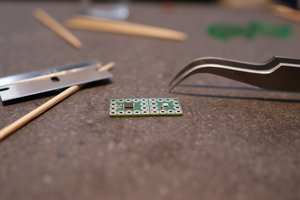
Fortunatelly, the spacing of the PCB antenna just matches the dimensions of readily available PCB-mount SMA sockets. I have used these SMA sockets from AliExpress for around 0.17 US$ per piece. If you prefer, you can use such RP-SMA sockets of course as well. Just make sure your antenna has the right connector.

Note:
Make sure to buy/use the same of a kind! That is, either SMA socket and SMA antenna or RP-SMA socket and an antenna with a RP-SMA  connector.

Using just a sharp knife or dremel, you have to cut and remove two small parts of the the traces as visible on the photo. Then you can solder the adapter to the board. To improve the ground connection of your socket, it is reasonable to also connect the now defunct rest of the antenna trace to ground. This gives proper grounding to your socket from both sides. 

Adding just a little bit of superglue to the socket on the back of your board not only helps you keep the socket in place while you solder it but also gives additional stability.

  • 1
    see description

    Just cut / remove the pcb as visible on the photo.

    Also note that I've removed a little bit of soldermask on the end of the pcb antenna and the groundplane close to it.

    Don't forget to solder the ground trace/bridge on the left side.

View all instructions

Enjoy this project?

Share

Discussions

pedrofilipe32 wrote 09/20/2019 at 21:41 point

see this link https://imgur.com/a/o0HViw9  of image  

 it is normal to continue between these two clues as you can see the image I put in ?

  Are you sure? yes | no

pedrofilipe32 wrote 09/20/2019 at 20:51 point

good, seen from behind the antenna. still has left pin to middle pin connection when it shouldn't have
I already cut the line between the first track and the second, and is giving me continuity with the multimeter when it should no longer. it's normal ??

  Are you sure? yes | no

rcull wrote 07/11/2019 at 19:40 point

Basically you gently expose the small bits of copper (image 4 is the best) with a knife as per the images in the post. Then you solder between the 2 contact points.. i.e you bridge a contact between the 2 points.

I've managed to find a more detailed guide at the link below. It's in Italian but a simple google translate does the job.

https://hassiohelp.eu/2019/03/02/zigbee-cc2531-antenna/

  Are you sure? yes | no

B wrote 04/28/2019 at 21:04 point

before and after as reported by zigbee2mqtt link quality on a router. Red arrow was where the antenna was installed. https://www.screencast.com/t/3C9ZDwjTW

  Are you sure? yes | no

emaillj wrote 04/17/2019 at 11:59 point

Put a phone light/torch behind the old antenna and I believe you will see that there's a bridge to ground in a lower layer of the PCB - triangular shape object. This looks to go to the visible trace closest to the corner where the new connector fits.

That might explain the results @MikeCC and @data found?

It would be interesting to test without the edge ground pin on the SMA connector soldered to the trace as then I don't think the connection will be made.

  Are you sure? yes | no

data wrote 04/17/2019 at 12:08 point

Just look at the schematics at https://www.mikrocontroller.net/attachment/366900/Antenne.jpg and you will see, that the rf coupler (named B1) is grounded.  When you cut the antenna trace to the right there is still the ground connection via B1...

  Are you sure? yes | no

Jon wrote 04/15/2019 at 13:48 point

Hello @data , sorry I'm very beginner at this and I've never done any type of mod before, I want to make sure I am doing this correctly. Do I cut the places I circled in red and solder the place I circle in blue? Thank you.  https://i.imgur.com/8vavkRZ.png

  Are you sure? yes | no

wimpie007 wrote 04/12/2019 at 19:37 point

@data does it make a big difference?

(parts are ordered, will make this also! THANKS)

  Are you sure? yes | no

data wrote 04/12/2019 at 09:13 point

Both are fine, but optional. If you are not sure, just omit it...

  Are you sure? yes | no

MikeCC wrote 03/24/2019 at 19:54 point

I have cut / removed the pcb at the two points as visible on the photo. Then I checked if there is still a connection between ground and the point where I have to connect the antenna. Surprisingly there is still a connection between ground an antenna connector although I cut the pcb at the two points. This is not correct, right? Is there any other point I have to cut/remove?

  Are you sure? yes | no

data wrote 03/24/2019 at 21:17 point

I just checked with one of my adapters with a multimeter, and there is indeed still a connection to ground. Since I don't have the schematics at hand at the moment,  I can't tell why it is there. Maybe it is due to some rf-frontend protection circuit which shorts unwanted voltages to ground.
However, the antenna works, at least according to the improved signal I get. 

  Are you sure? yes | no

MikeCC wrote 03/25/2019 at 13:56 point

With my multimeter I measure 0 Ohm resistance between antenna connector and ground. So this means that it doesn't make any sense to cut the two points from pcb, right?

You can find schematics here:

http://www.ti.com/lit/ds/symlink/cc2531.pdf

https://www.mikrocontroller.net/attachment/366900/Antenne.jpg

  Are you sure? yes | no

data wrote 03/25/2019 at 15:48 point

I just checked the schematics: the measured connection between the antenna output and ground is fine, since it is connected via R9 (0 Ohm) and B1 (rf-coupler) to ground.

What do you mean with 'it doesn't make any sense to cut the two points'?

Since you've asked this question, I guess you have no idea of high-frequency/RF signals. The RF-Frontend of your stick consists of R9, C5 and B1. Simply said, this frontend is designed and built in such a way, that DC voltage and all unwanted signals (other frequencies than 2.4GHz) are shorted to ground so that only the 2.4GHz frequency signal is fed into the chipset.

Hence it makes complete sense if you measure a ground connection with your multimeter. And of course you still need to remove the stripline the way explained. The distance between signal and ground is vital in order to maintain impedance. See e.g. https://en.wikipedia.org/wiki/Impedance_matching

  Are you sure? yes | no

data wrote 02/09/2019 at 10:39 point

How you do it shouldn't make much difference. But it is probably easier to just bridge the small gap with some solder.

Actually, the best would be to keep the ground connection as short as possible and make  a short bridge to the resistor next to the ground-leg. However, the risk that you accidentally remove/displace the resistor is too big.

  Are you sure? yes | no

adriankoooo wrote 02/05/2019 at 11:25 point

". Then you can solder the adapter to the board. To improve the ground connection of your socket, it is reasonable to also connect the now defunct rest of the antenna trace to ground. This gives proper grounding to your socket from both sides. "

The ground connection is improving the signal? Do you mean connecting like this? 

https://imgur.com/a/qSaHPb8

Or do you mean soldering like this?

https://imgur.com/a/hZcj3zN

  Are you sure? yes | no

Raymond Uphoff wrote 04/11/2019 at 12:34 point

Which one is it? I want to do this antenna-mod myself. To me your first pic makes the most sense. No RF-antenna-part running as ground. I could be wrong though...

  Are you sure? yes | no

Similar Projects

Does this project spark your interest?

Become a member to follow this project and never miss any updates