 matseng
PROJECT LOG ENTRIES
1 - Size matters
2 - Soldering the grid
3 - Frame bend-styles
4 - Oscillators
5 - Assembly
6 - Final results - with videos
64 LEDs in a matrix on a wireframe controlled by 16 astable transistor oscillators to resemble a computer panel from a 70's TV show
Already have an account? Log in.
To make the experience fit your profile, pick a username and tell us what interests you.
1 - Size matters
2 - Soldering the grid
3 - Frame bend-styles
4 - Oscillators
5 - Assembly
6 - Final results - with videos
The finished device looks rather good, not bad at all actually - if I say so myself. ^__^
Below is a video of it running on a single 3 volt coin cell battery:
Running at full 5 volts with diffusor:
I tried my best to make soft corners on the two power buses that will form the frame around the LED grid, but it was very hard to get the sizes and spacing between the two even enough. So I ended up with just plain square corners bent with pliers .
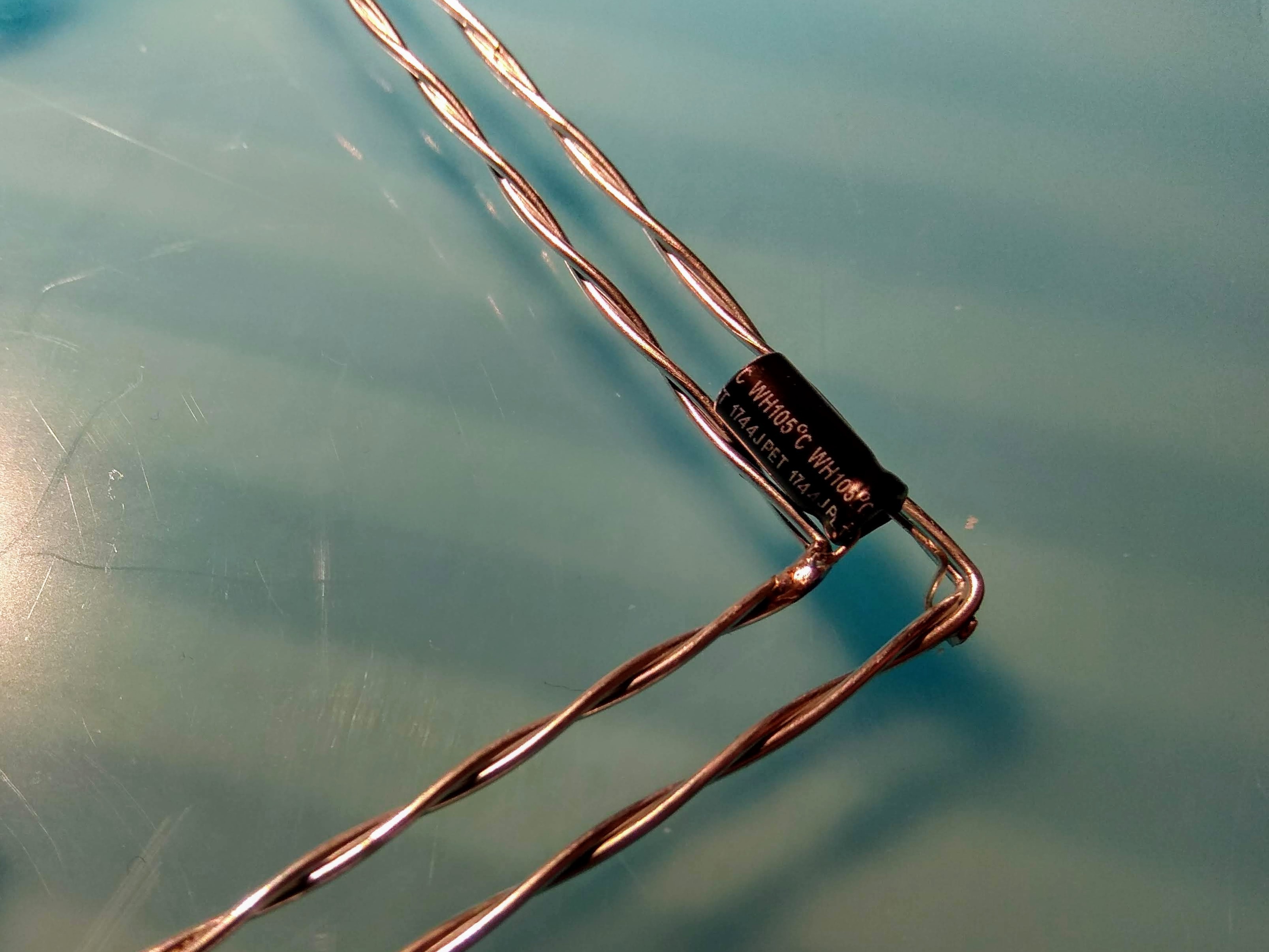
To keep the distance between the two frames I installed a small electrolytic capacitor in each corner.
Then I added all the oscillators spreading them out evenly among the top/bottom respective left/right edges.
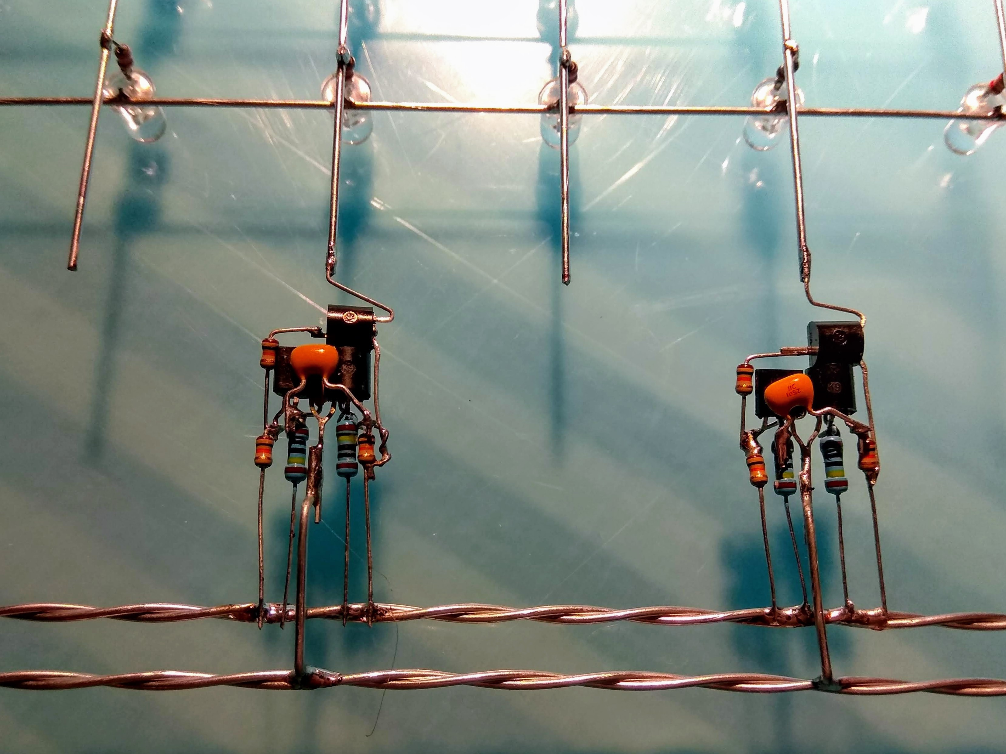
The inner frame is the VCC so all four resistors are connected to it. The outer ground frame is connected to the common emitters of the transistors by a jump-wire that is bent so it doesn't short out the VCC frame.
Since the LEDs are in a matrix I need to have the oscillators both push VCC into columns and also connect GND to the rows. So I need two different types of modules for that
The oscillators themselves are just the bog-standard two-transistor, four resistors and two caps thingie. And to be able to push and pull current I added a NPN driver transistor to eight of them, and a PNP driver to the remaining eight.
Using 1uF caps and 1M for the timing resistors I ot about 0.7Hz when running at 5 volts, slightly slower at 3 volts.
Eight of each of the two types of oscillators are needed for the 8x8 matrix.
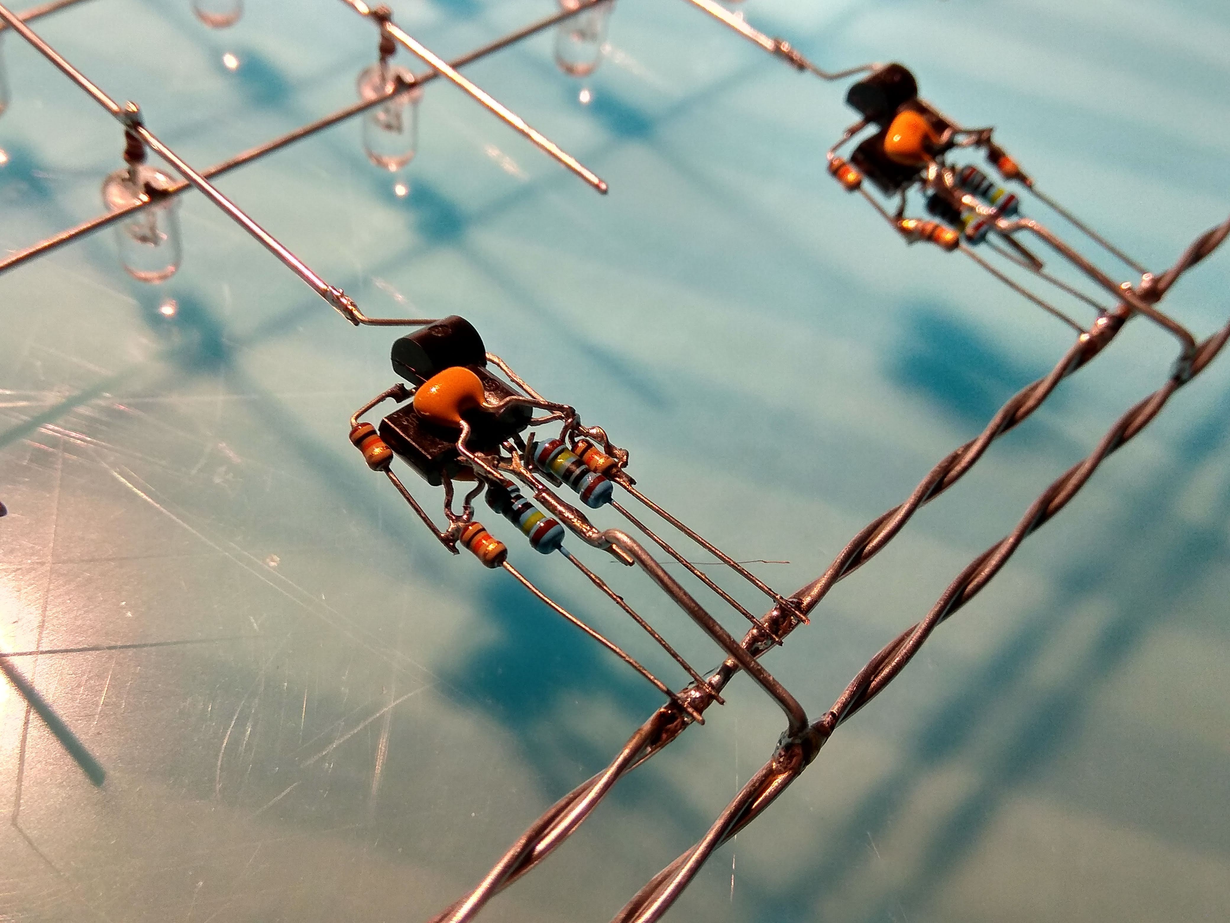
I re-discovered the usefulness of using blu-tack to hold parts while soldering - but even using that it took quite a while to freeform 16 oscillators with 9 parts each.
This is one of the NPN-driver oscillators that pulls a row to ground when active. The PNP oscillators looks more or less the same except for the top transistor that is in a slightly different position to access VCC instead of GND.
The power bus/frames will be rather large with sides at 30 cm / 1 foot and I suspect that they might become a bit rickety with only made with a single 1mm wire each.
So I tried to straighten two wires at the same time using the usual technique - and it worked just fine!
But now I have to choose how I should do the corners - either just straight square 90-degree bend or a a smooth bend.
The grid inside the frame is very strict and square, so it might look good to have the frame a bit soft to contrast to the inside. Or it might look out of place... I have a hard time choosing.
I think I'll go for the soft bend - and maybe I should make the radius even larger.... Hmmmm....
Since I learned how to make straight and nice pieces of wire when I did my WireZ80 for the Circuit Sculpture Contest I quickly made sixteen pieces of 22 cm wires while my 3d-printer churned away at a small jig I made in Fusion360.
The jig doesn't cover the full 8x8 area, but rather just a smaller 4x4, but that is enough to keep the LEDs straight and spaced perfectly.
Since the LEDs are white high-brightness I did some tests and found out that a 2k2 resistor in combination with the voltage drop of two transistors lights them up enough to not be annoyingly blinding.
Soldering the LEDs onto the horizontal wires, and then the resistors followed by the vertical wires took about two hours.
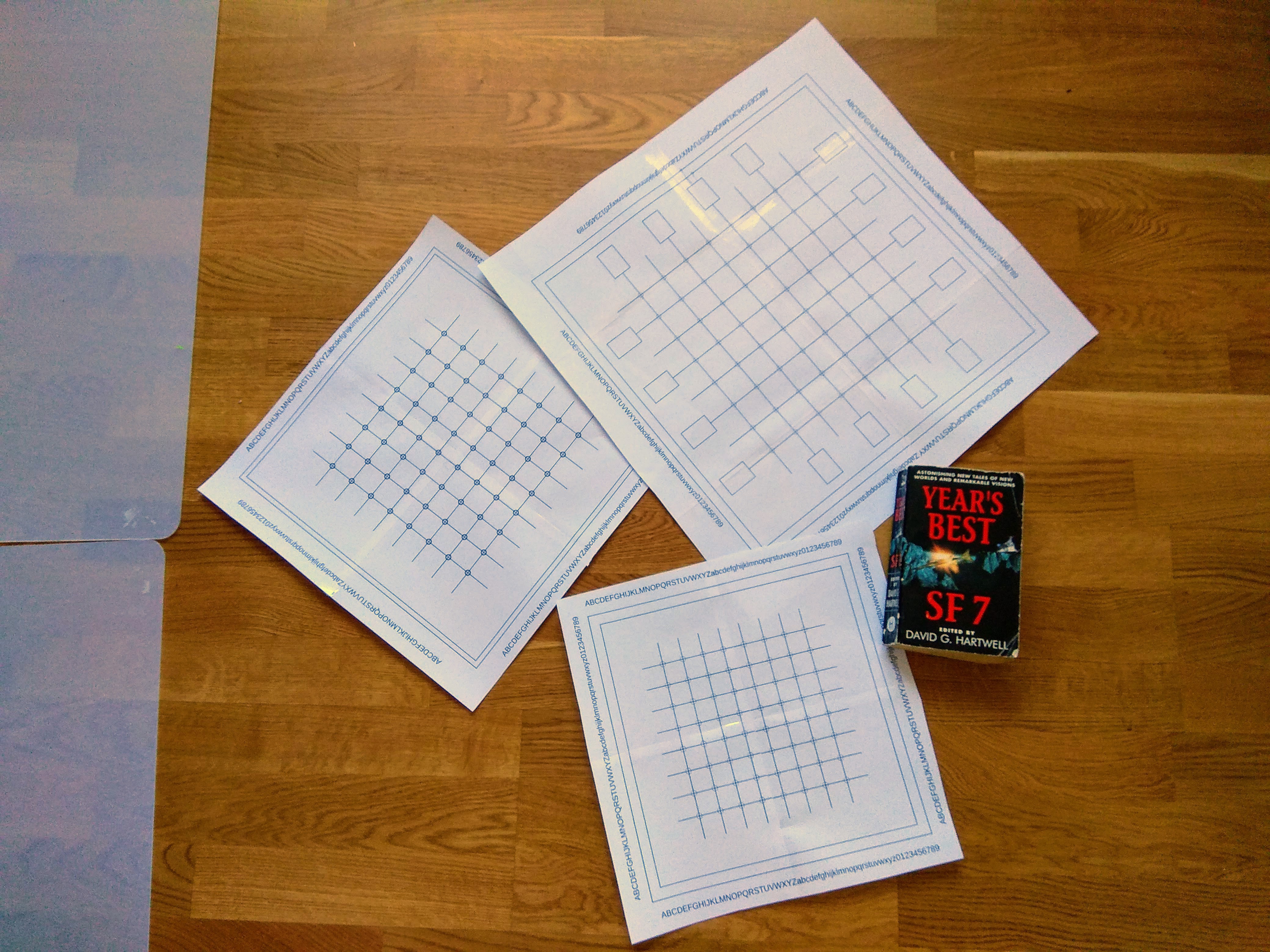
To get a feeling of the actual size of the grid at different spacings I decided to print a few samples on paper (and taped together to full size). I tried 30mm, 25mm and 20mm spacing.
My original though was that 30mm maybe was a bit on the small side, bu after printing it I discovered that it rather was too big.
I settled for 25 mm (about one inch) between the 5mm LEDs.
Around the grid of LEDs there will be a frame made out of two steel wires for the power distribution.
Then the oscillators will then be freeformed and put between the grid and the frame.


It's a long time since I've seen transistors being drawn that way. Where did you pick that up?

Probably back in the late 70's. It was a long time since I actually saw any of these in the wild in any modern context, but there's some variants of it used in the 60's which was probably to differentiate the from contact point transistors.
Today I tend to use it when I just want to draw a quick and dirty sketch by hand since they are faster do draw compared to the "regular" symbol. And luckily enough they are still easily recognizable by anyone used to the the regular symbols....

Nice :-) I tried that with #Daisy which I have yet to complete. Not as easy as it sounds lol, I hope you get it blinking nice and random. ;-)
It is blinking away now. The component tolerances makes the patterns slowly change and morph into new patterns over time. II'm really happy with the outcome.

Loved the WireZ80, can't wait to see this one blinking!
It is aliveeeee! And is actually really good looking both unpowered and while running.


 Miroslav Zuzelka
 Morning.Star
 Jorj Bauer
 Daniel Domínguez
Beautiful! We should have run a freeform circuit sculpture contest or something...