-
Speaker and Rechargable Battery
03/04/2019 at 16:06 • 0 commentsSomething that has been pressing on my mind is the portable-ness of this smartwatch, or should I say the lack of for this project so far.
So far, in order to hear the music playback, you must either use headphones with a 3.5mm jack (though this only works for a Raspberry Pi Model that has a headphone jack), or it has to be connected to a TV and played through HDMI. Not very 'elegant'.
Then there is the power side of it, it needs to be constantly connected into the mains plug socket, so its portable-ness is determined by the length of the micro USB cable you have.
I want to over come these barriers. The main reason for why, is as part of this University Project, I have to give a presentation on it, during which I don't want to be constricted to the wall with one wire, and connected to the TV so hear the sound by another. That is completely defeating the point of the wearable tech, 'watch' form factor of the project.
So I've been researching possible methods to do this. Giving the watch a rechargeable battery seems easy enough, I've found some components on Pi Hut which should do the job, and some googling helped me figure all this out, seeing what other people had done etc. The hardest part has been a speaker system for it. As the screen uses all my GPIO pins, thats the main method from what I can tell and most used from reading online forums etc which is used to connect the pi and give it some speakers etc. So I can't go for the straightforward pHAT offered by PiHUT.
But then I came across this:
https://learn.adafruit.com/pigrrl-2/overview
A guide by adafruit for building a retro gameboy type device using the Raspberry Pi. More importantly, it used a rechargable battery system and speaker system, along with a touchscreen. This is my answer.
-
New Strap
03/04/2019 at 15:47 • 0 commentsSo I've come up with a new idea for a strap. Now that I am building up a larger experience using these FSR Sensors, i've noticed that they will not require at least one sturdy/rigid surface to be able to measure from. I believe these sensors will work just fine using something along the lines of a traditional leather strap. As long as its tightened sufficiently around the wrist, to create some small pre loading that I can account for, it should then be able to pick up differing measurements all the same.
I've tested this by wearing an old watch of mine and by using double sided sticky tape, secured a sensor head to the inside of the strap.
IT WORKS.
But with one drawback, it works a little too well as a heart beat sensor. It picks up my pulse slightly, so without any movement of the wrist/hand for gestures there is a continuously changing measurement. This is going to prove very difficult to compensate for when coding the algorithms for gesture recognition.
For now, I think I'm going to focus on the glove form factor I have mentioned previously just so i can get something built that works within the time frame of this Masters Project. The plan: to secure the sensors at the finger tips of a glove, and then casting measurements by pinching together fingers which will lead to actions on the 'smartwatch'. If I the time, I will revisit the strap sensor form factor.
-
Watch Strap Rethink
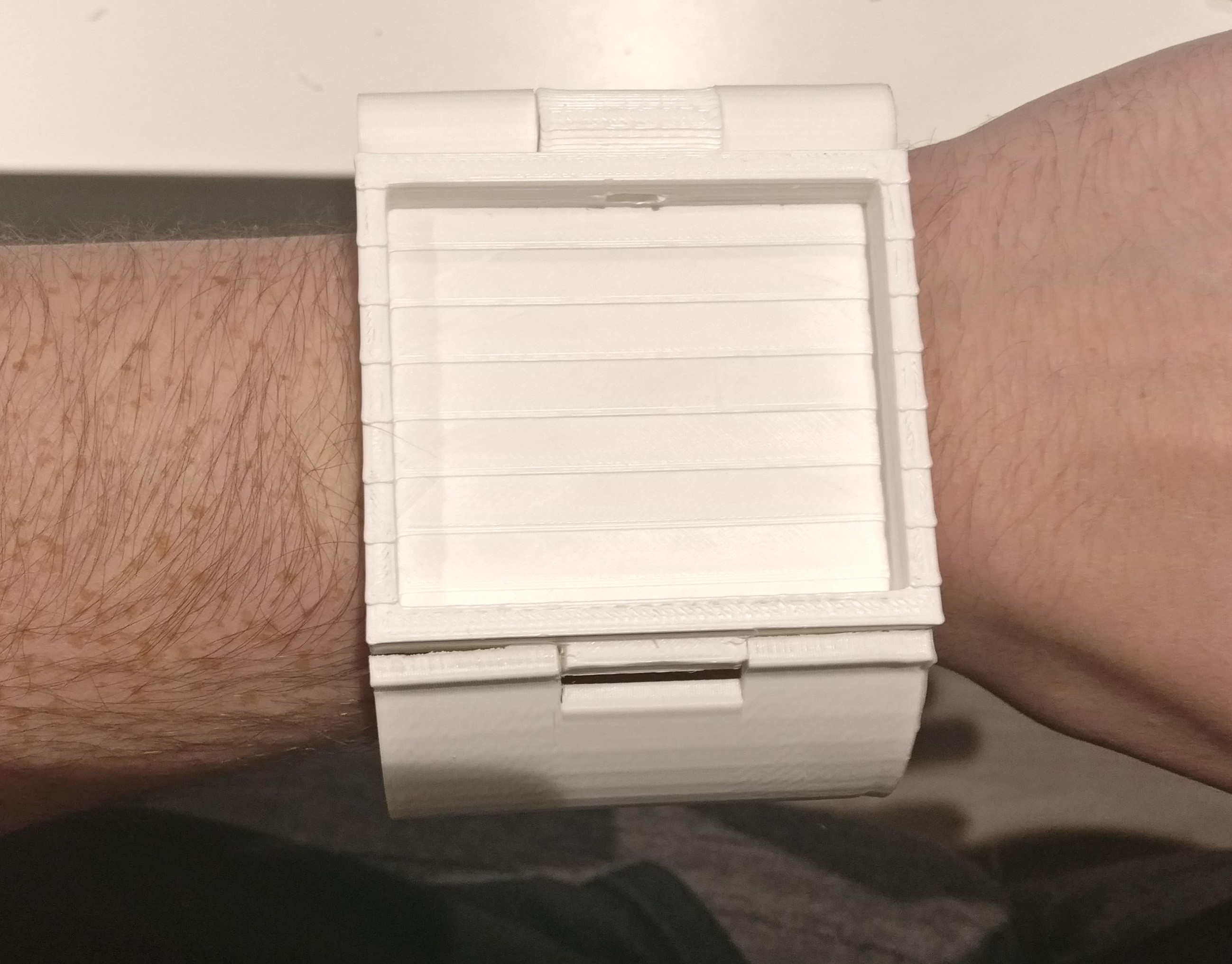
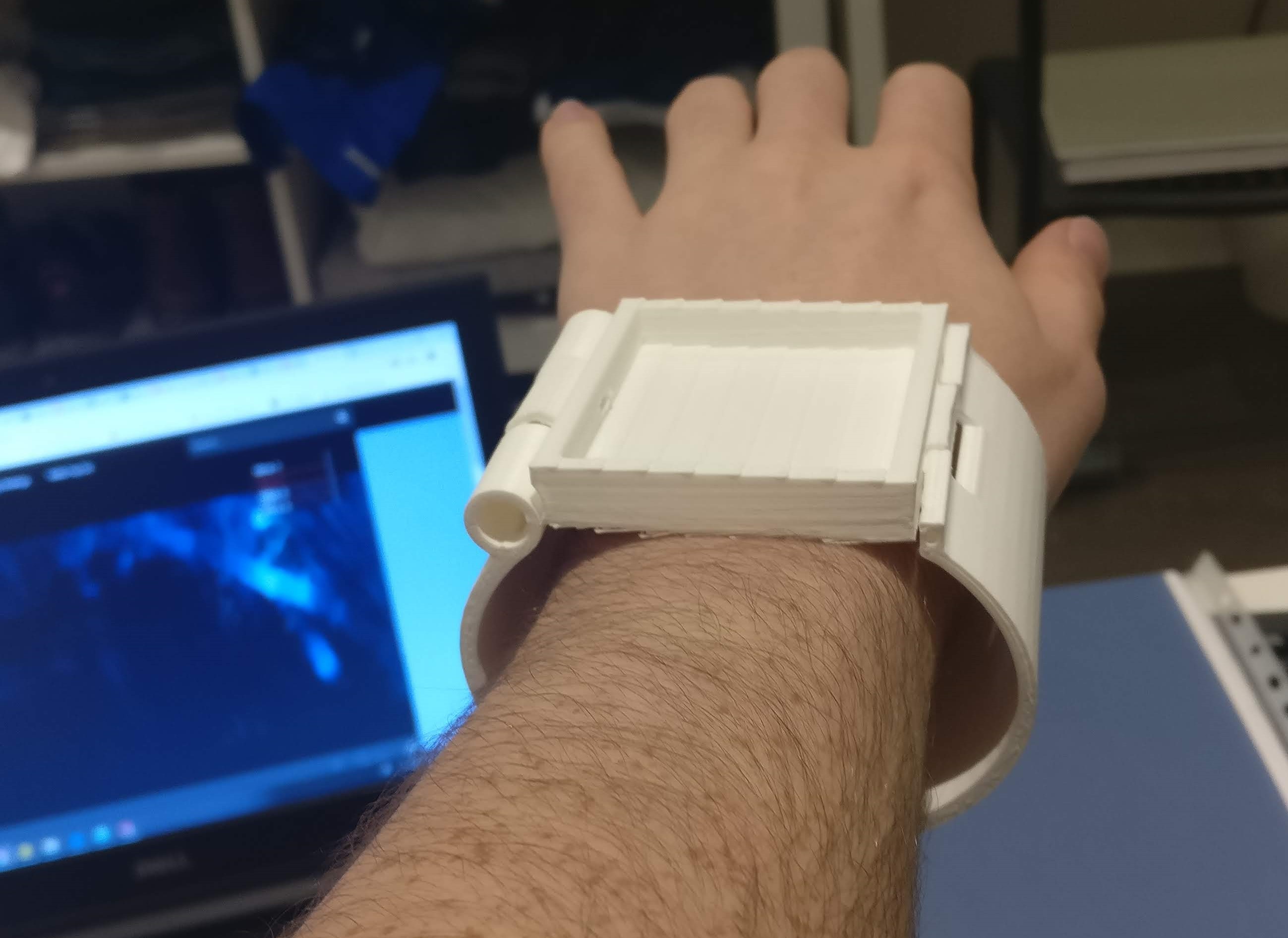
03/04/2019 at 15:40 • 0 commentsAs you might remember, I attempted a watch strap which I detailed in an earlier log, it looked like this:
![]()
I've been playing around with trying to figure out attaching the sensors to this to read forces from my wrist, but its proving more difficult than I expected. It's hard to know how I should fill up the empty area around my wrist to 'squish' the sensors up to my wrist to generate that needed contact for measuring. As you can see here:
![]()
It's made me think, maybe there is another way, and easier way to solve this... go back to the drawing board so to speak. But that is the benefit of 3D printing - allowing the rapid prototyping of ideas.
-
GUI Aesthetics
03/04/2019 at 15:29 • 0 commentsFollowing on from my comments in the last project log, I've started to redesign and improve the look of the GUI. Trying to make it more professional looking. The main 'Homescreen' is divided up into 4 scroll-able columns to access various 'apps' and started using icons to identify these 'apps'.
![]()
-
Sensor Control (09/02/19)
03/04/2019 at 15:17 • 0 commentsOne large hurdle overcame today. I now have the FSR Sensor outputs transferring to the Pi and displaying in real time within the Kivy app when running. I've added in a little if statement as well for a couple of sensors, if sensor 1 reaches a value of 400 or more, then a song will start playing. If sensor 2 reaches a value of 400 or more, this will then stop the music. This illustrates towards the final idea that I want to achieve, imagine say using a glove and the sensors placed at the fingertips, pinching various fingers together would trigger these actions. I also have 3 LED's connected to the Arduino, which turn on indicating the threshold values have been reached by the sensors as described above as a sort of visual indicator outside of the app.
Here's a video:
Sorry for the glare on the screen and the small writing is hard to see. Now that the functionality is pretty much there, I will start focusing on the aesthetics of it all more.
Python threading was the answer in the end. And I have to shout out my good friend Lewis Holmes who helped me with the underlying theory/methodology of threading and how it works to help get this code up and running and working. I will upload all the files of my coding so far with this date in the filenames (09,02.19). Also, following my friends advice, I have split up into multiple python files importing into the main, various parts of the GUI, so as to keep it more manageable.
-
Python Threading
02/28/2019 at 22:33 • 0 commentsSo after the success of getting the FSR data from the Arduino to the Raspberry Pi, its time to get those values into the Kivy GUI in real time too. However, its not as simple as just copying the serial test code into the GUI unfortunately. As the serial read code is a loop of constantly checking the port for new information and then printing it if so, this loop causes a problem when running it inside the app loop of the GUI. The app (I believe) gets stuck in this serial read loop and cant complete the rest of the GUI code, and thus doesn't work.
So after some research, I've come across a python coding concept called threading which I believe is my solution. Threading, as I understand it thus far, is the ability of running multiple threads at the same time essentially. These threads can be different process or functions etc. So in essence, I will have the GUI running in one, the serial reading in another which will feed its information into the GUI. Hopefully this will overcome the looping problem i'm facing.
Update on the other part of the project, I have brought a couple more sensors and changed the codes to reflect these extra sensors.
-
Serial Connection Fix
02/28/2019 at 22:25 • 0 commentsIt seems it was just a matter of changing the Baudrate of the Serial Connection which has provided the solution to my problem. I changed the baudrate from 9600 to 115200 and it seems to be working fine now:
I've accessed the Raspberry Pi through an SSH connection to run the serial test python file.
A simple post splitting process to separate the actual measurement from the letters can be done, so i'm not too worried about that format it is being delivered in.
*Note, if you are using the serial code files I've uploaded you may need to change the port for the code to 'look at', mine works for ttyUSB0, but this could be different depending on which one you use for yours. A way to check is open the terminal on the the raspbian desktop and run:
ls /dev/tty*
this will then list all the ports beginning with tty. Now plug in your arduino to a USB port and run the command again. A new port will appear at the end of the list, this is what you must reference in your code.
-
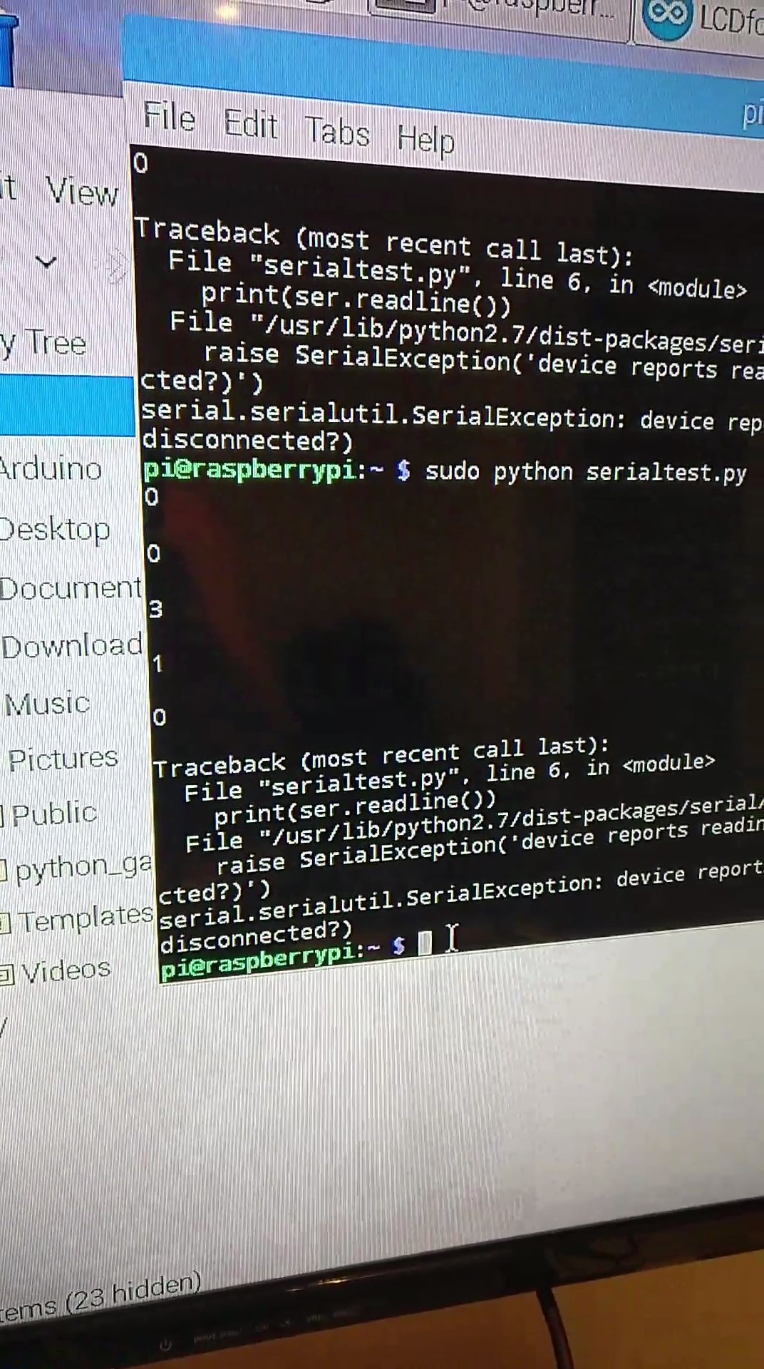
Serial Connection Error
02/28/2019 at 21:21 • 0 commentsSo the serial connection is up and running, however there seems to be a bug, it will only read 4-5 measurements from the Arduino before the connection cuts out and the device is 'disconnected'... Some more research is needed to figure out whats going on here...??
![]()
-
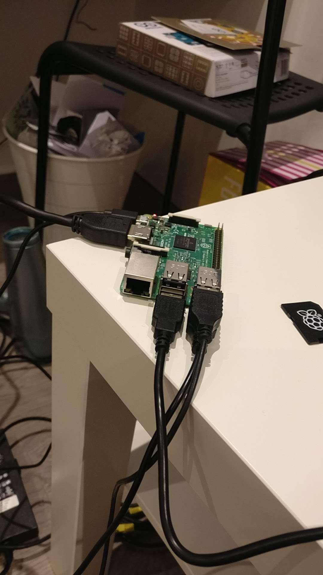
Serial Connection
02/28/2019 at 21:14 • 0 commentsSo attempting the serial (USB) connection between the Arduino Uno and Raspberry Pi and then sending the FSR data from one to the other. I'm using a Raspberry Pi 3 Model B, this model has the most connections, everything you need in terms of HDMI output/USB ports to make this stage of the prototyping quick and easy.
![]()
So here, I have a keyboard and mouse connected to the two USB ports on the right. The power cable of the Arduino Uno is then connected into the lower USB on the right. Then you can see the HDMI cable outputting to a TV I have connected and the Raspberry Pi power cable at the rear.
After a google search on the serial connection and reading/writing to it from the perspectives of the Raspberry Pi and Arduino respectively it seemed fairly simple.
This stage, I used essentially the code available here for the basis:
So I wrote up a quick serial test python file. First I just want to get the data to the Pi itself, I will then move onto getting it into the Kivy GUI. I will upload this serial test file and the Arduino serial code file for that side of it too.
-
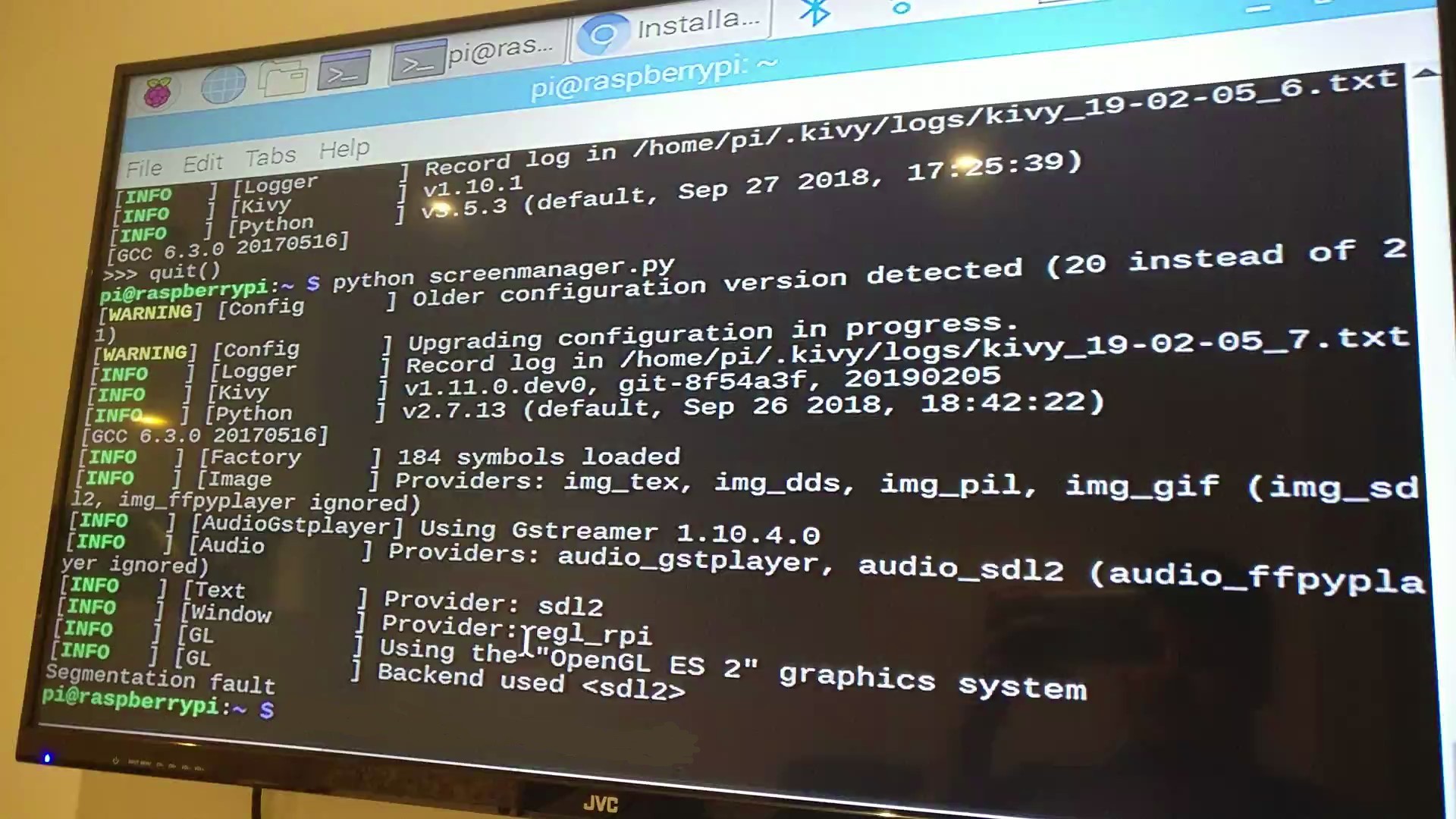
Segmentation Faults
02/28/2019 at 20:58 • 0 commentsSo as mentioned in my last project entry, I had some issues when trying to run my GUI code on the Pi itself, as before I have always ran it on my computer. The main problem I had was this segmentation fault that would appear when trying to find the window for my code to run:
![]()
I overcame this by setting some environmental variables at the start of the code, like so:
import os
os.environ['KIVY_GL_BACKEND'] = 'gl'
os.environ['KIVY_AUDIO'] = 'sdl2'
Gesture Controlled Smartwatch
A larger, more functional smartwatch with gesture controllability