 Ken Yap
I bought a Raspberry Pi Model B a few years back. I had intentions of turning it into a thin client to my Linux workhorse, running an X server, and X programs would run on my workhorse. I got that working but it was too slow for comfortable use, after all it has only 512MB RAM and a single core ARM processor. I later bought a Pi 2 and that's another story.
At the time I wasn't (back) into hardware hacking, so I didn't do anything with the GPIO pins. I've kept updating the Raspbian version on it but otherwise the Pi has been sitting on my bench idle.
It's easy enough to use jumper wires to connect the GPIO pins to a breadboard but I was looking for something neater. While prowling eBay for parts I noticed that I could get a kit comprising a 26 connector ribbon cable, a breakout board, and a small breadboard to plug it into. Connections to the GND, +5V and +3.3V to the buses on the breadboard are also made. Since the full kit only cost a few dollars, I didn't hesitate to buy. If you are tempted to use your own breadboard, note that the spacing of the pins on the breakout connector is tailored to the breadboard. I have the 26 GPIO pin Pi, not the later 40 GPIO pin Pi's for which analogous breakout kits are sold.
The kit depicted in the photo landed in my mailbox, and it only took a few minutes to put everything together, see instructions below. The breadboard is small but it's easy enough to expand it to another breadboard with jumpers. My only gripe is that my polycarbonate case doesn't have an opening to put the ribbon cable through, the manufacturer wasn't targeting hardware hackers, so I'll have to operate the Pi without the cover.
I then proceeded to install the wiringPi library using git. This provides an API very similar to the Arduino wiring API. Bindings to other languages are also available.
I connected a 220Ω resistor in series with a LED between P0 and +3.3V, compiled the good old blink.c example, and ran it. Worked great. NB: Do not put more than 3.3V on any of the GPIO pins. This is one major difference from the Arduino. Also it's preferable to sink current rather than source, as the limits are higher.
I've set up the Pi to automount a directory on my Linux workhorse so that development files actually live on my workhorse and are backed up, etc. I'm also going to plug in a USB WiFi dongle so that I can use the Pi untethered from the Ethernet switch.
Now to use the Pi for hardware experiments. It's a full Linux environment so you can use any of the tools there, including debuggers like gdb, whereas on the Arduino, most people use the IDE and the intrepid use the command line for the AVR tools, and debugging uses the serial console. There is no download delay as the program doesn't have to be squirted through the USB serial interface.
Enjoy your new development platform!
 Craig Hissett
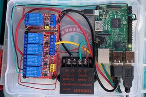
 blinkingthing
 Guy Dupont
 Jdaie
Jdaie