Close
0%
0%

RC Plane Force-Feedback System

Making the controls of an RC plane feel like the real thing.

Similar projects worth following
Most RC controllers use springs to create back pressure on the control sticks. These work fine, but obviously do not really provide a sense of 'connection' with the plane. You can pull full back on the elevator as quick as you like, but you don't feel how the plane reacts to that control movement. You only get to see the plane move. I think a lot of precision then is lost, or at least harder to read, only relying on visual ques from the plane. Especially as the plane becomes larger and there is more momentum in the system causing a delay between moving the control surface and the plane physically starting to move. Being able to feel the real-time force feedback on the control stick, like a lot of full-size planes, could potentially provide faster and more solid indicators of how the plane is flying - when a stall might be approaching or if the plane is traveling too fast and putting a lot of stress on the control surfaces.

This project is aimed to create a force feedback system for fixed wing RC planes. The actual forces imparted both by the controllers hand on the joystick and the control surfaces against the servos will be measured and summed together to create the feeling that the user is directly pushing or pulling the airplanes control surfaces. 


For now on the control side I will be using a 3D printed joystick that is actuated by servo motors. These servo motors will generate the resistance and feedback to the controller. In-line with servo control rods will be force gauges to measure the force being imparted by the controller. On the plane side the servos on the elevator and ailerons will have force gauges in-line with the servos measuring the force of the wind against the surface.

To give the effect of feedback, the force measured on the joystick and the force measured on the plane's control surface will be summed together. The net force from this sum will then be translated into a velocity term for both servos in the joystick and on the plane. This velocity is then integrated into a position and sent to the servos.

Loosely the dynamics are represented as:

v = (force1 + force2)*gain;  // gain is a coefficient to tune in how the system reacts
x = x + dt*v;   // dt is the period the system is running. Target is 60Hz

In general the control surfaces will be acting in the opposite direction of the user input, so the net force will be small or zero (given no violent control commands like aerobatics or such). Thus the servos will not move much as the velocity term will be small. However the user will still need to apply a force to hold the control surface.

Of course to make this whole system work there needs to be a wireless link to ferry data between the plane and the joystick so that the next velocity and position values can be calculated. For now I am planning to use a cheap 433MHz module pair that emulates a serial port. The boards are completely transparent to a connected micro-controller, data is sent to them over a serial port and they handle all communication details. They can be configured via AT commands for parameters such as baud rate, channel used, transmit power, etc. The module used is listed in the components sections.

This is of course a cheap module and the usage will be in a plane with a noisy electrical system and at a significant distance, so if I encounter signal integrity issues I will try to switch over to having serial data carried over a FrSky Taranis X9D. 

step - 153.78 kB - 03/28/2019 at 00:36

Download

  • Force Gauge

    Matt Dombroski03/26/2019 at 00:25 0 comments

    The centerpiece of this project and the component that took the most time to develop is the force gauge. The basic idea of most force measurement is knowing the relationship between the displacement of an object to the force that caused that displacement - i.e. a spring. For measuring the force on a control surface of a plane however the 'slip' from a spring is undesired. The servo can only travel so far and in addition any slip will cause a bit of a time delay to moving the control surface.

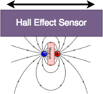
    An obvious answer would be strain gauges. However, strain gauges are extremely sensitive, need quiet electronics (hard to do on an RC plane), and typically need bulky mechanical structures to be attached to. Instead, I happened to read another HaD article featuring [Wold Tronix] linked here, which shows a project with almost an identical goal as this one, and showed a great idea for force measurement. Here an analog hall effect sensor placed over a very small magnet. The hall effect sensor part number is the Allegro A1304 and a 1/32 diameter neodymium magnet are used, as per the recommendation from the article. 

    The hall effect sensor is sensitive to both the magnitude and direction of the measured magnetic field. Paired with the small diameter neodymium magnet, the sensor is extremely sensitive small movements, probably in micrometer range up through about 1 or 2 mm. So very little displacement is needed and a stiff, strong sensor body can be designed. This particular hall effect sensor is also very easy to interface, it is completely analog and only needs an analog port on an Arduino or any other embedded platform. One note is that it runs off 3.3V, so watch out before you plug it into the 5V rail of an Arduino!

    Now, while [Wolf Tronix] builds in the hall effect senor into the servo arm and into a jig frame for the servo, I wanted to make a more traditional discrete force sensor that was physically separate from the servo. Part of this was because I did not want to modify the servo arms and possibly weaken them, nor did I want to design a frame for the servo that had to be design or at least built into the airframe. I also decided to do this in case I came up with a project down the road which didn't use servo (say stepper motors or linear actuators); I didn't want a design that was bound to a specific servo size and style.

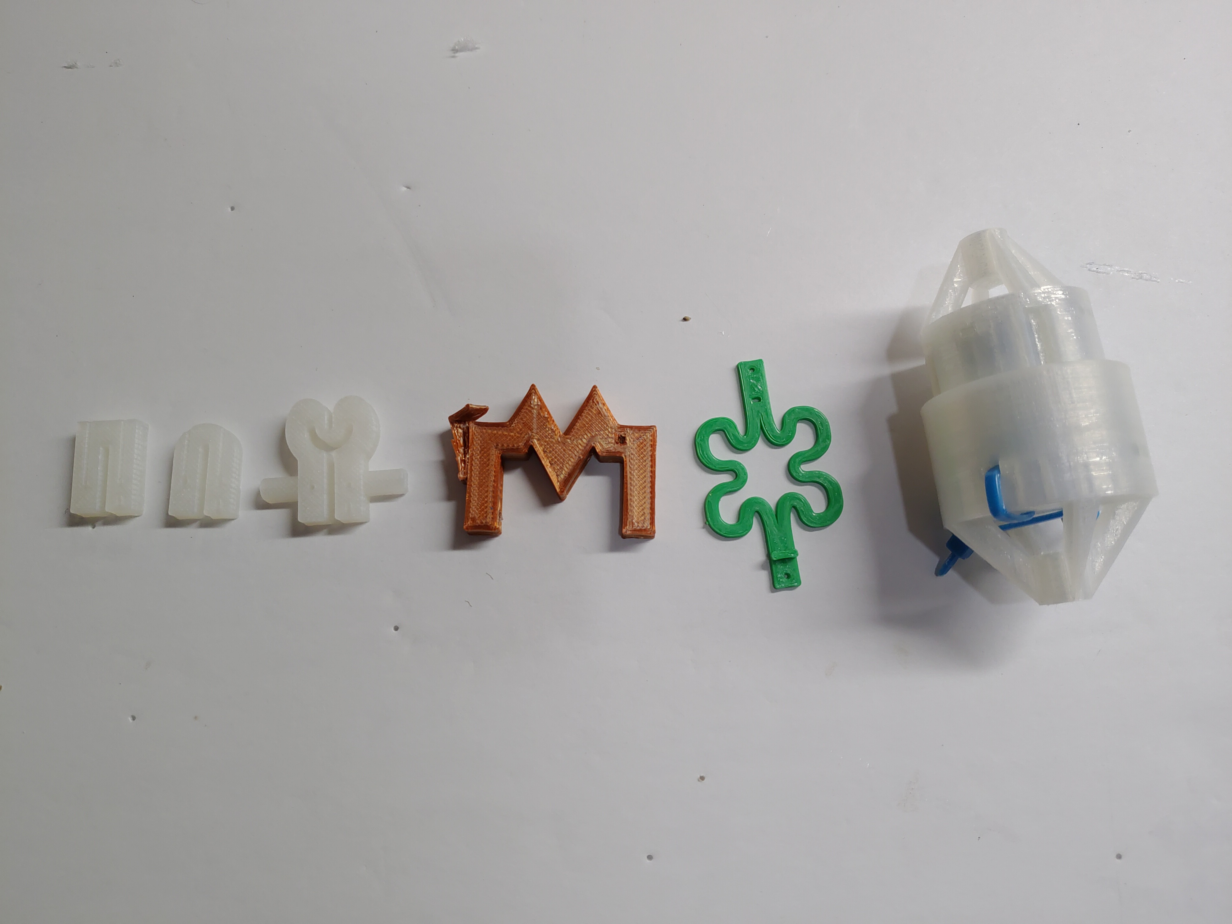
    A good force gauge will be linear over its intended measurement range and have low hysteresis so that forces going one direction and then the other read the same values. For my design, I wanted to 3D print the gauge because its faster and more accurate than me hacking at something manually, and I have no access to lathes or CNC's. I went through a number of design ideas:

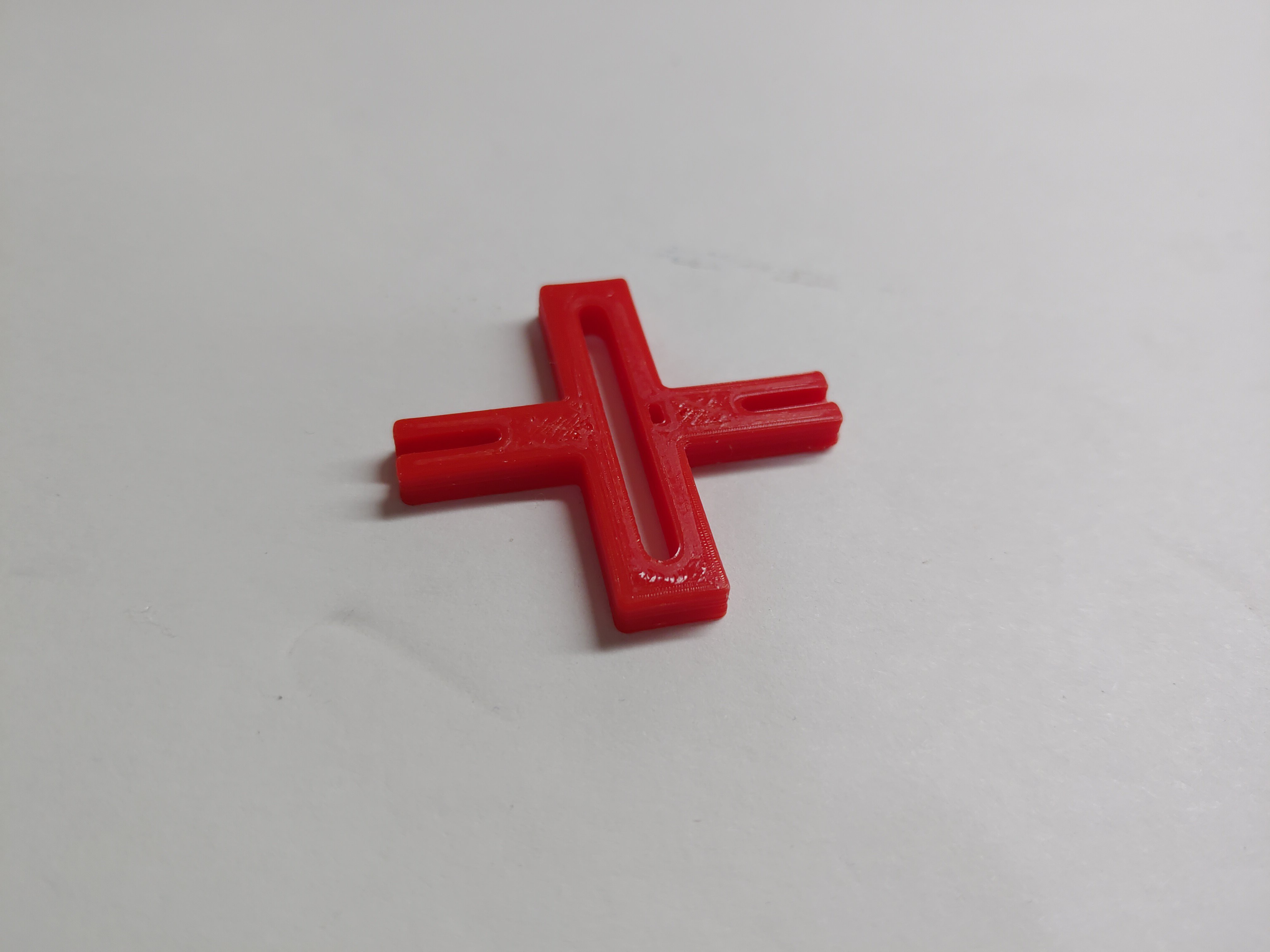
    And each had they're own set of drawbacks that took them out of the running. (That big round one at the end would have probably worked well through, just far too heavy for use on an RC plane, and it needed springs more precise assembly...). The design I found to work the best was predictably, one of the simplest:

    Why this design? A few things I have observed from testing:

    1. 'Short' gauges work better overall. Short here means the bending area is small and the arms transferring the force are close together. This reduces the amount of flexing possible, but the hall effect sensor is sensitive enough to need only fractions of a mm of travel. Why keeping the bending area short is useful is due to minimizing undesired flexing directions. For example look at the green clover leaf prototype in the pictures above. As a force gauge it works very well, but because the arms are so spaced there are really two major directions of bending - compression and tension and bending up and down (think bending the plane of the gauge into a curve). Due to the geometry of the sensor, both the compression/tension flexing (of interest) and up/down flexing (of no interest) are measured with roughly equal sensitivity. So the result is looking at my sensor measurements...
    Read more »

View project log

Enjoy this project?

Share

Discussions

Dan Maloney wrote 03/04/2019 at 15:37 point

I like this idea. Along with FPV, it could really make the RC experience immersive. Keep us posted.

  Are you sure? yes | no

Similar Projects

Does this project spark your interest?

Become a member to follow this project and never miss any updates