Gabriel D'Espindula
Briefing
After a few minutes wondering how to do this, I came up with a very simple idea. I'll use the P2 connector as my interface, each audio channel will send a tone relative to X and Y and the MIC will receive another tone to indicate when the user is solving the maze, so I can set up a timer.
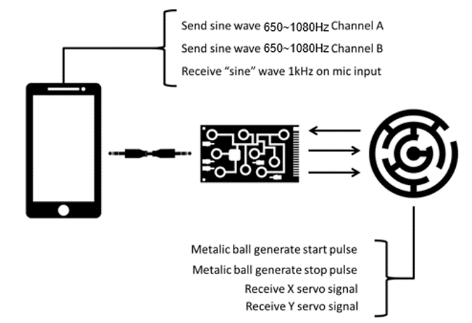
The values here were just randomly chosen, nothing special about it and honestly I've got this values after testing the circuit, to design it I had in mind only the central frequency about 750Hz. And I made the circuit somehow it was easy to modify that.
Blocks diagram
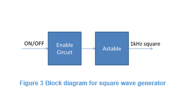
Cool! Next step was to create some blocks diagram and find out what components I would use for each block. In this case I'd divided all circuit in two diagrams, one for the audio signals received and other for the mic signal sent:
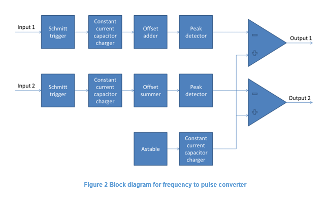
Notice that the output were meant to be directly connected to the signal pulse from the microservo 9g. if you google it you'll see that the signal is a 20Hz rectangular waive with high time changing from 1~2ms, but in reality this Chinese motors have a big tolerance, so I made a circuit reliable enough to calibrate this easily.
To do all this blocks I've used some 555 timers, Opamps and transistors only :) Check out the schematics at the documentation bellow.
I did add some pots to calibrate the zero position, it would fix the tolerance problem on those servos and made everything easy to calibrate, considering the UX depends a lot on how balanced the maze is in the center position.
I also choose PTH resistors in functions that might be good to change. I have in my inventory a lot of PTH values but not so many SMDs, so I put SMDs only where I was 100% sure I wouldn't need to change after doing tests.
If you see the PCB and schematics have some test points. I add them to facilitate calibration.
PCB
As all components are easy to find and have DIP package, I could even use a breadboard to try its functionality, but I din't see any critical point in the circuit, so I've chose to go straight to the PCB.
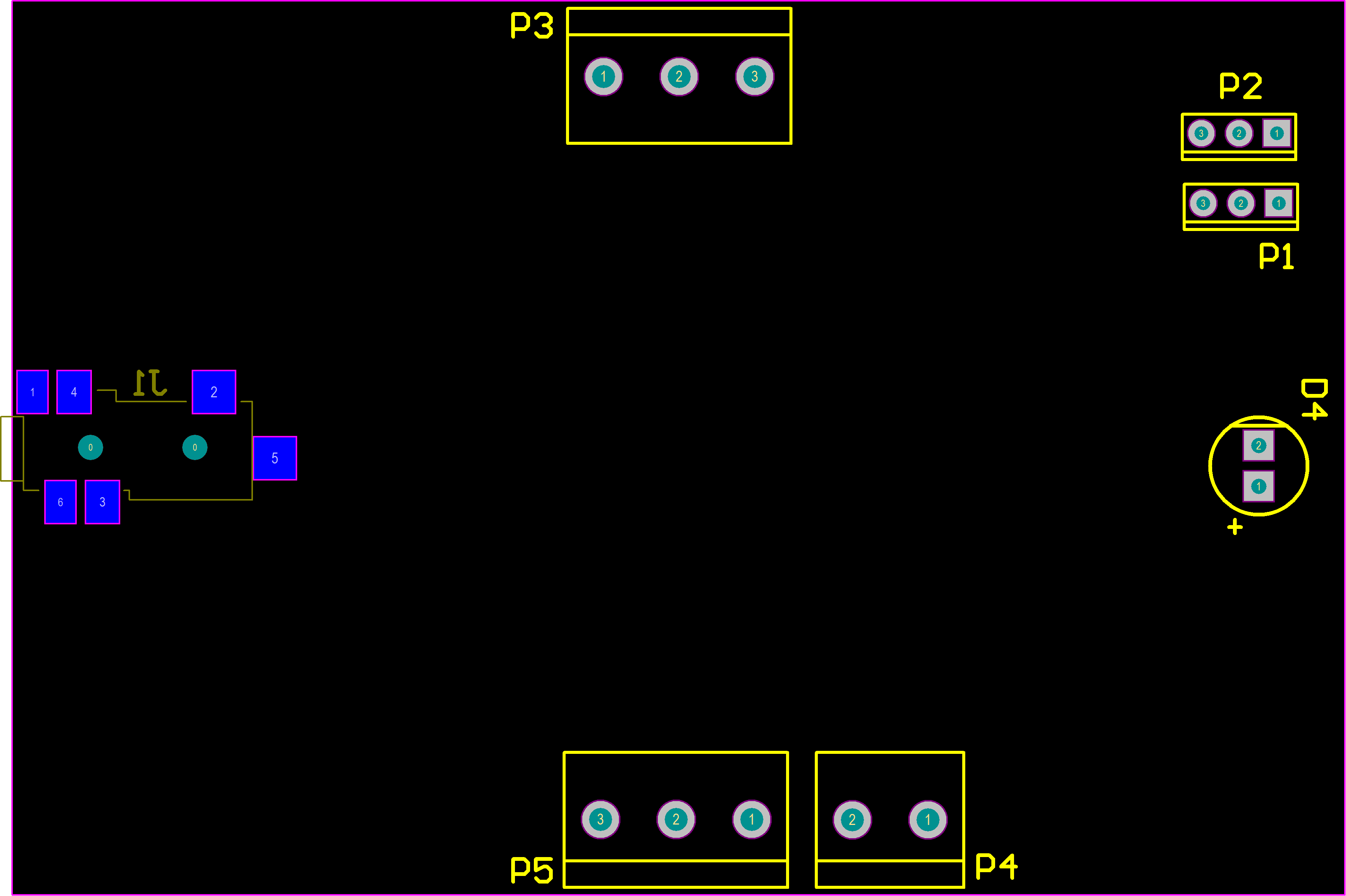
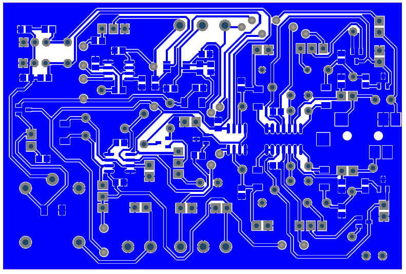
Alright, once the circuit was completed I needed to design a PCB. Here there was an extra challenge "make it in a single layer board, with constrains to use a milling machine"
I did the board on Altium designer, all files are attached, my goal was to create it withing the following rules:
- Minimum clearance: 0.2mm;
- Minimum via diameter: 1.27mm and 0,711mm hole;
- Board maximum size: 120x80mm;
- Board proportion: 3x2;
- Ground plane must be solid and shouldn’t have necks with less than 0.254mm;
- The circuit needs just one ground plane.
- The connectors and LED should keep near to the board outline, without any component between them and the edge;
- The connectors and LED must be in the following sides:
- P3 – facing up side;
- J1 – facing left side;
- P4 and P5 – facing down side;
- D4, P2 and P1 – facing the right side. The maximum number of jumpers is 10.
After a couple hours on Altium the design was ready to produce!
Assembly/first tests
After finishing the assembly I came up with the following test flow:
- Input a 650Hz 5Vpp sine wave in the TP3;
- Calibrate R9 to have a 3,6Vp signal in TP1;
- Input a 650Hz 5Vpp sine wave in the TP8;
- Calibrate R20 to have a 3,6Vp signal in TP6;
- Change R30 to have a 3ms high time square wave in TP12;
- Change R33 to have a 4Vp signal in TP13;
- Enable the U5 oscillator and calibrate R29 to have a 1Vpp in TP14.
- Vary the input frequency on PT3 and TP8 from 650 to 1080Hz to see the output vary high time from 1ms to 2ms.
I've used an oscilloscope to see the 1kHz output and a two channels function generator instead of a phone for now. Swapping the two input channels could simulate both motors moving in all range....
Read more »
 Russell Kramer
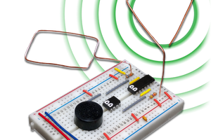
 David Levi
 John Wetzel