 Scott Clandinin
What is it?
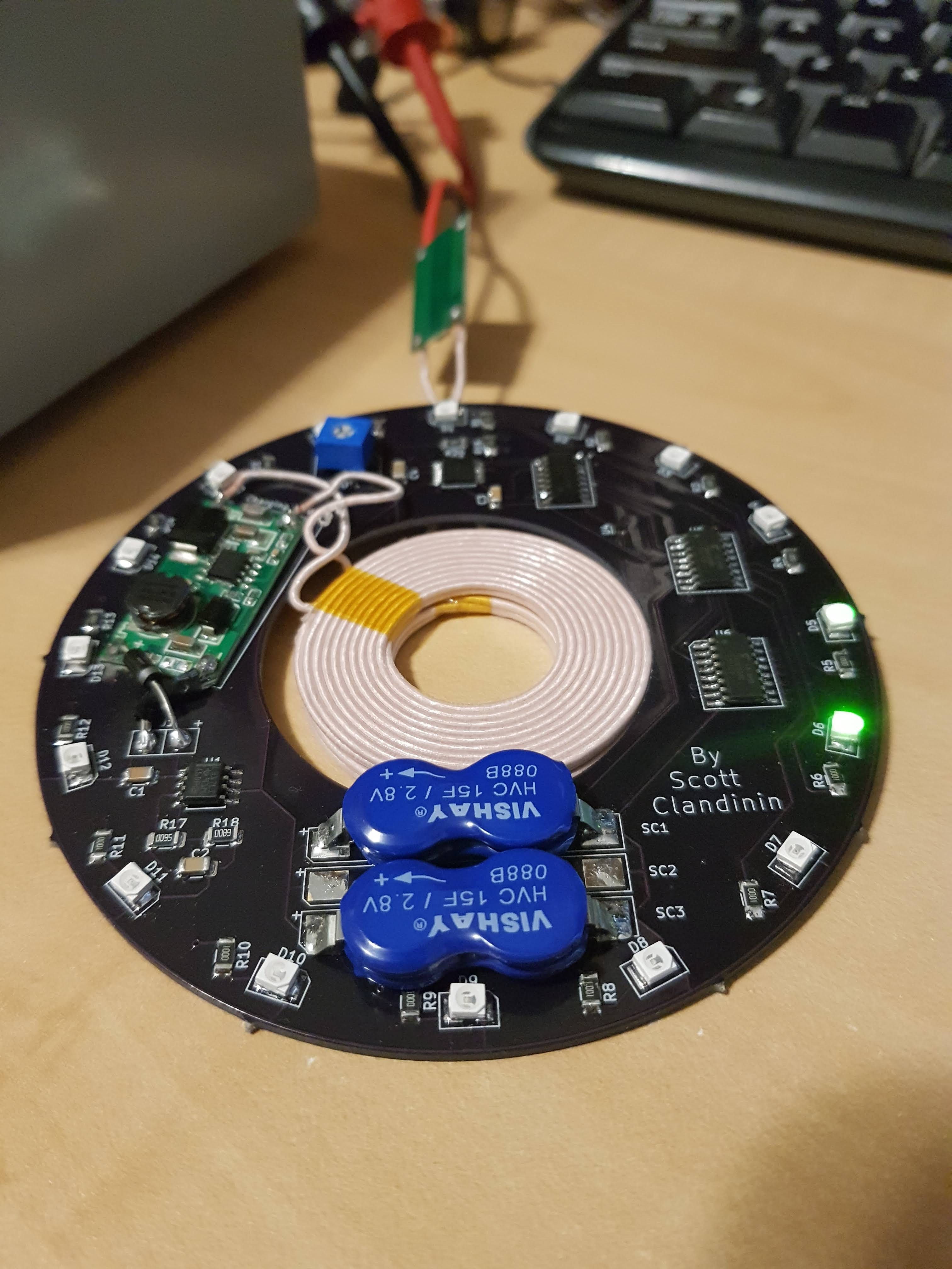
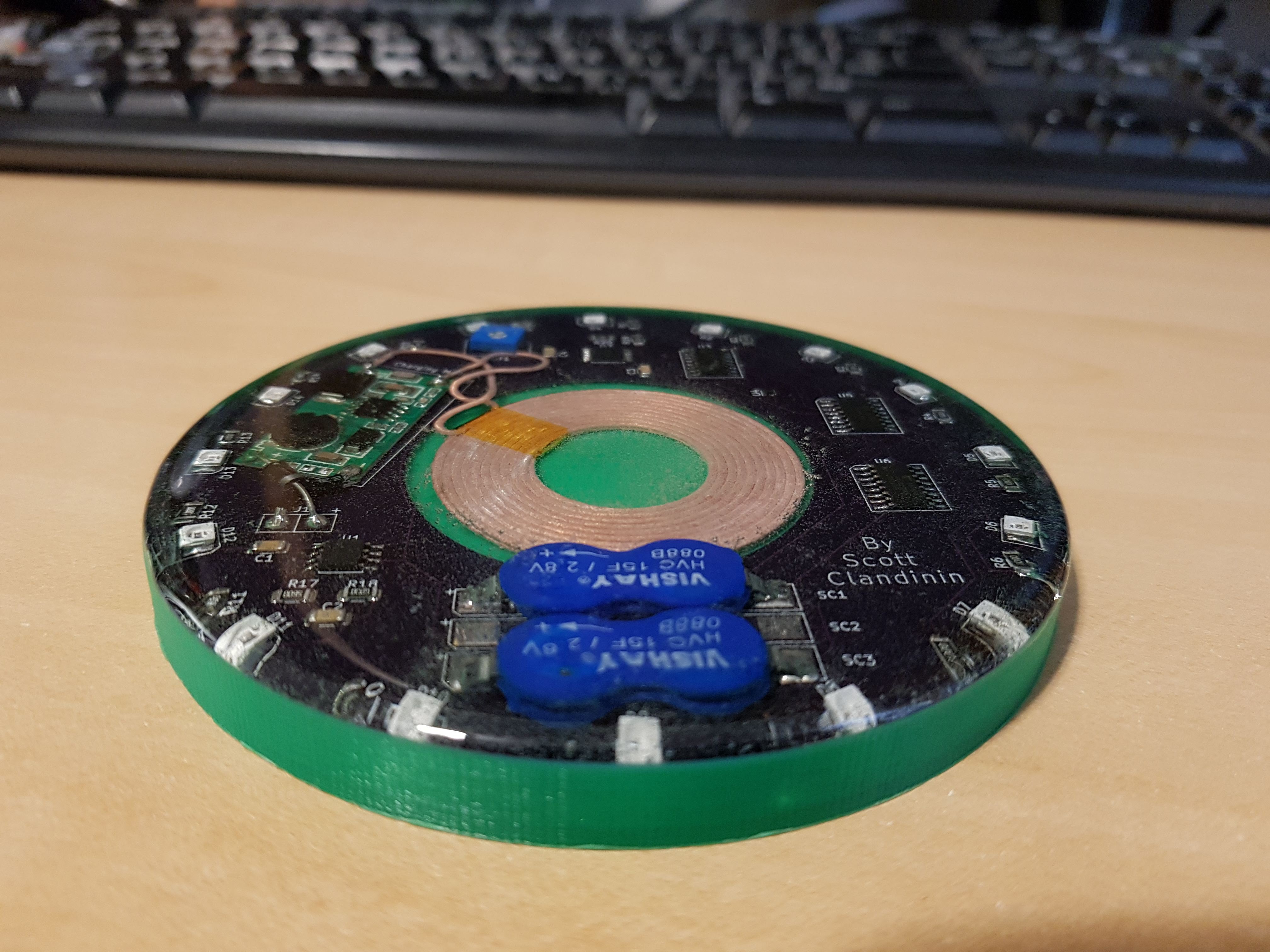
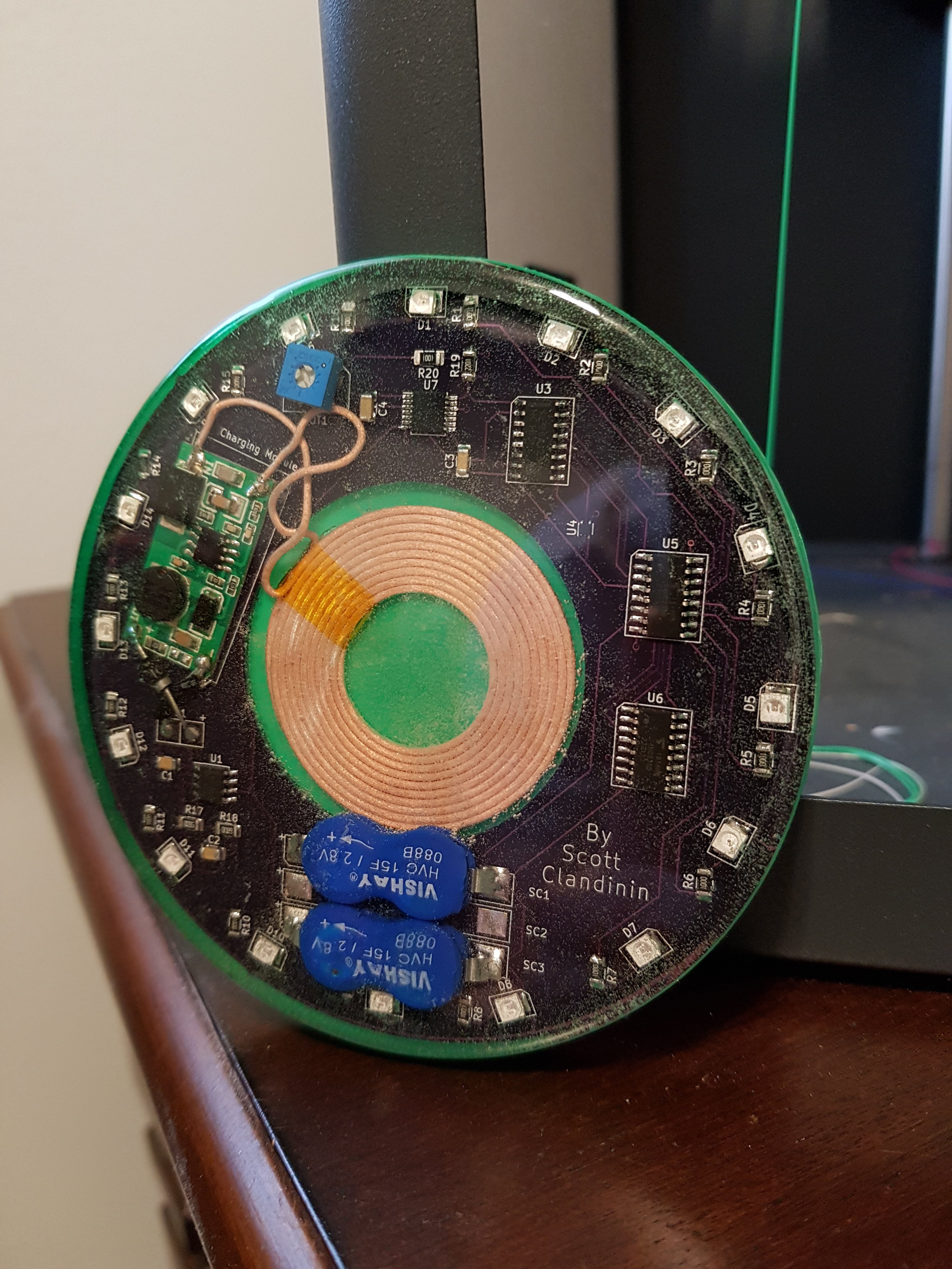
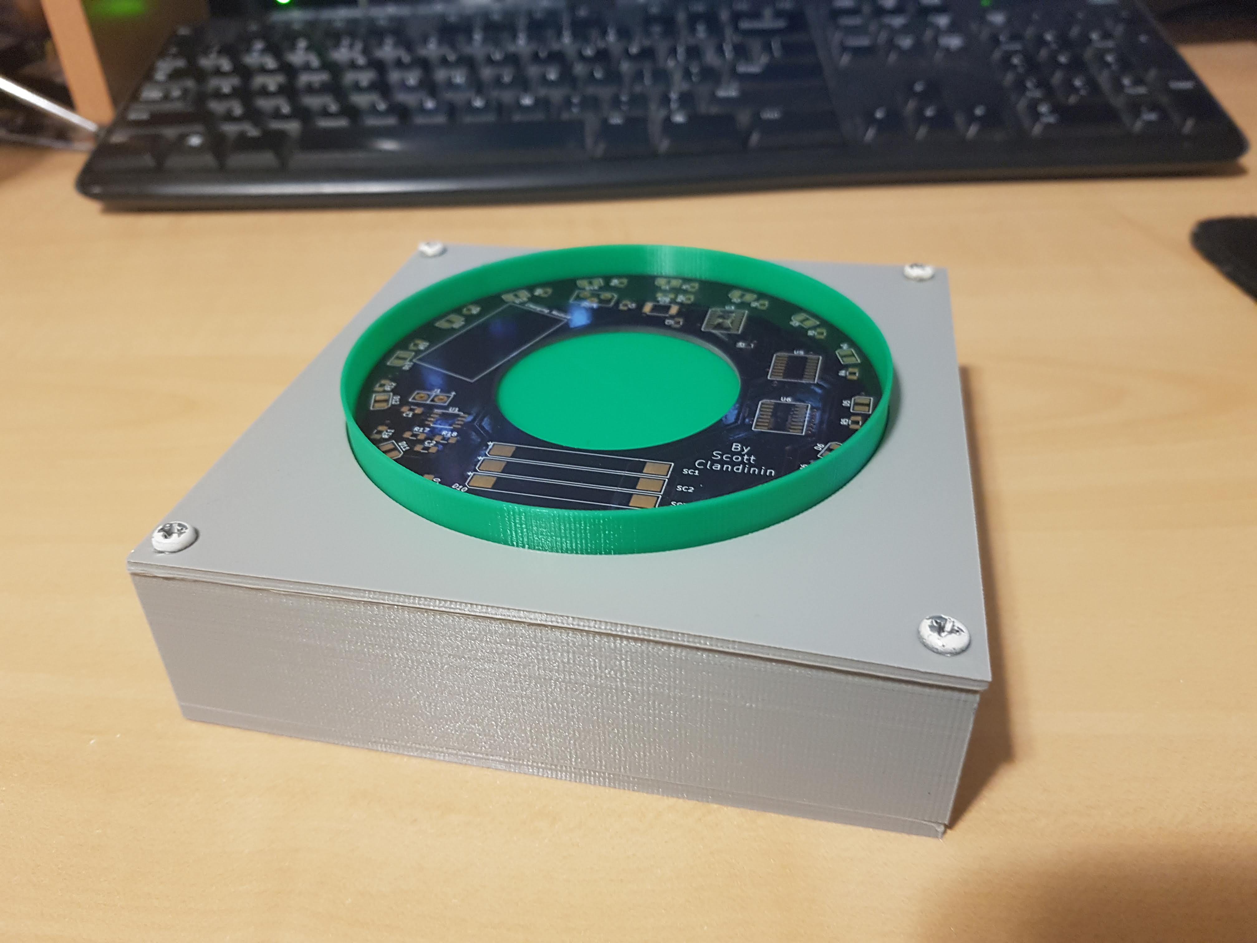
LED drink coasters are nothing new, but this one is different than the others in more than just aesthetics. LEDs around the perimeter of the coaster rotate around, with one LED on at a time. This device can be wirelessly charged.
What is the goal of this project?
This basis of this project was to explore the feasibility and operation of a rechargeable device utilizing supercapacitors rather than traditional batteries.
What sets this apart from other LED coasters?
-Ease of use
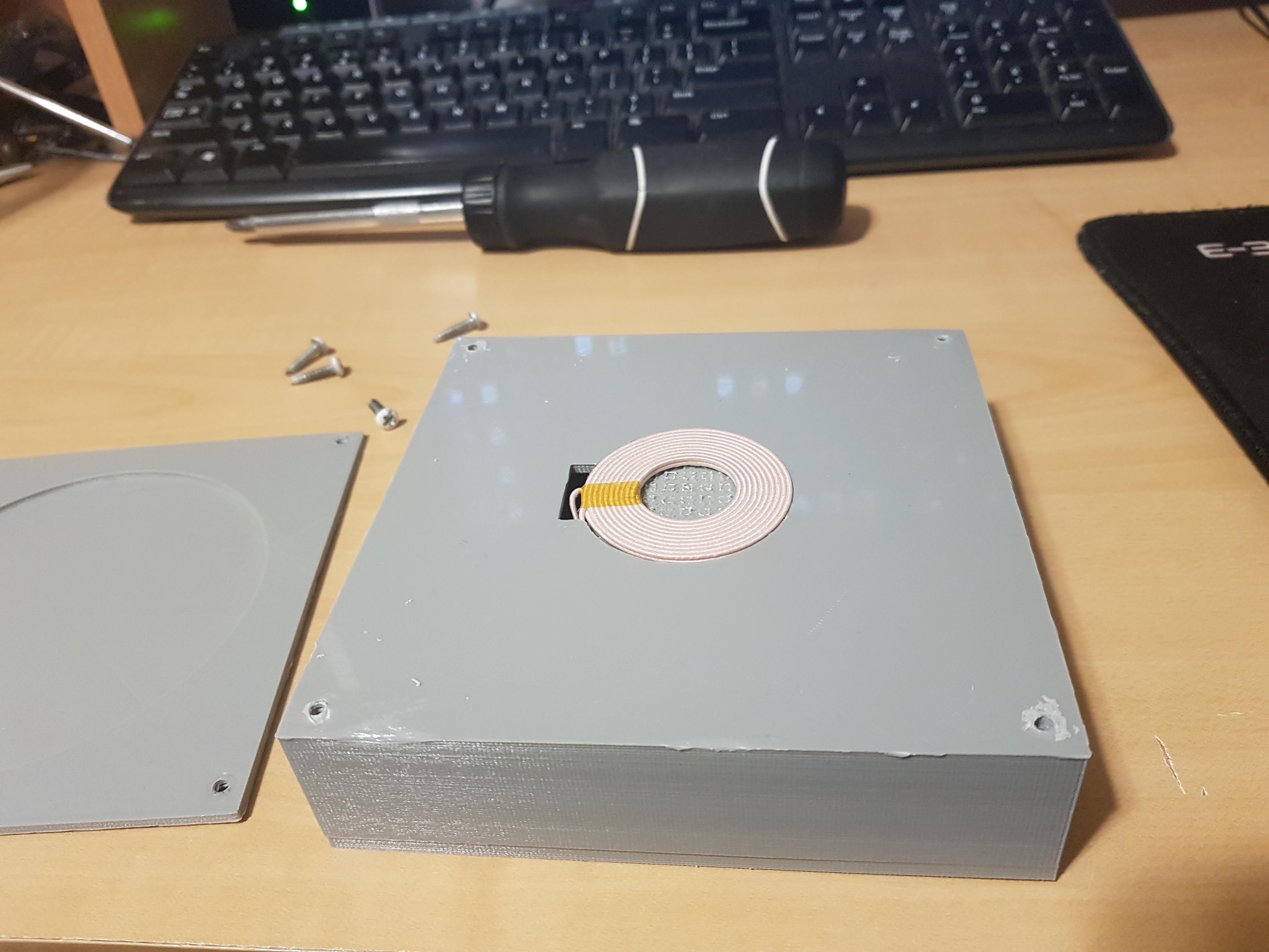
- Wireless charging allows for easy recharging. No need to plug anything in or replace batteries.
-Lessened environmental impact
- Using supercapacitors means there will be no batteries that end up in landfills. Many LED coasters on the market generate a lot of waste in one-time use batteries.
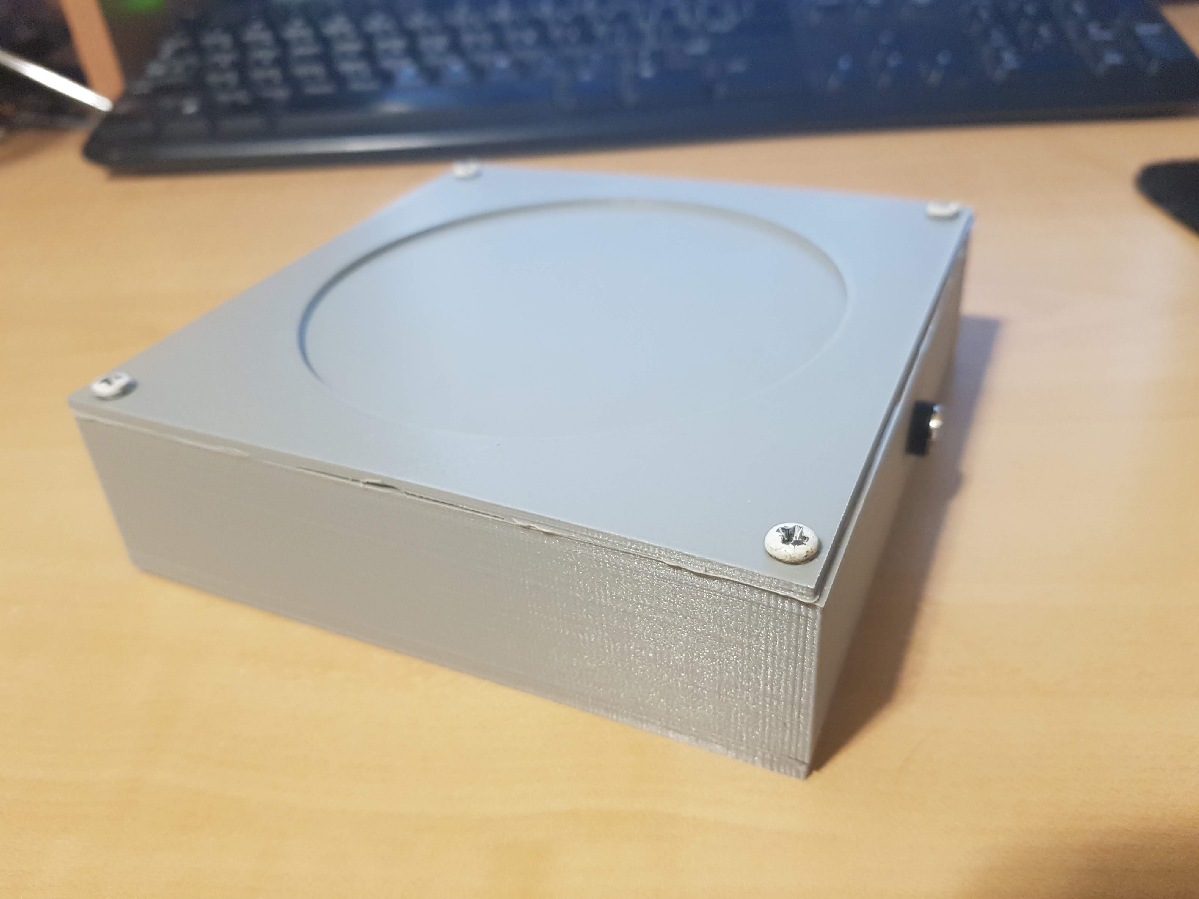
-Slim and aesthetic design
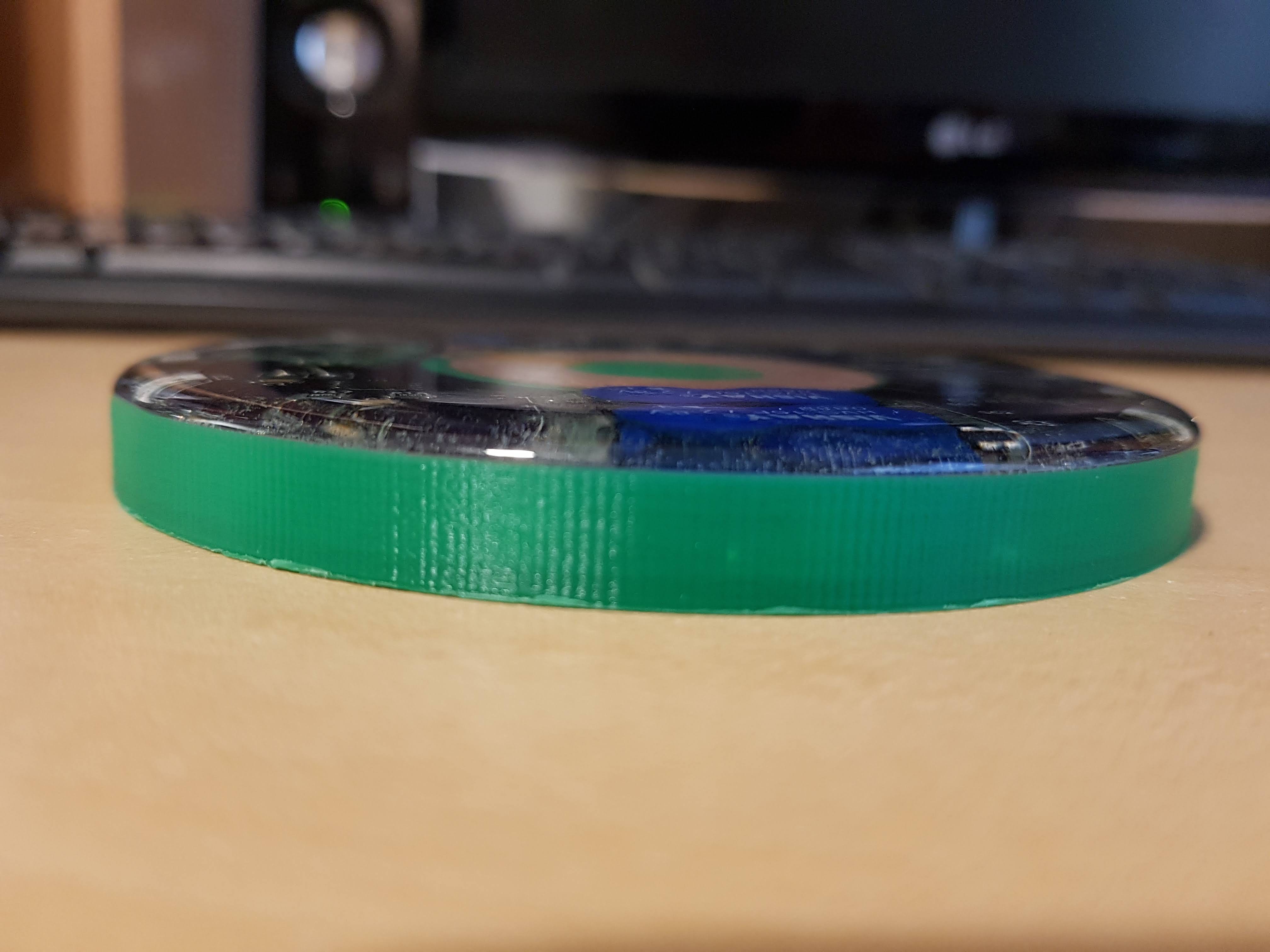
- The features of the PCB are the focal point of the aesthetics. Using supercapacitors rather than batteries allows for a slimmer design than other rechargeable LED coasters.
-Durability
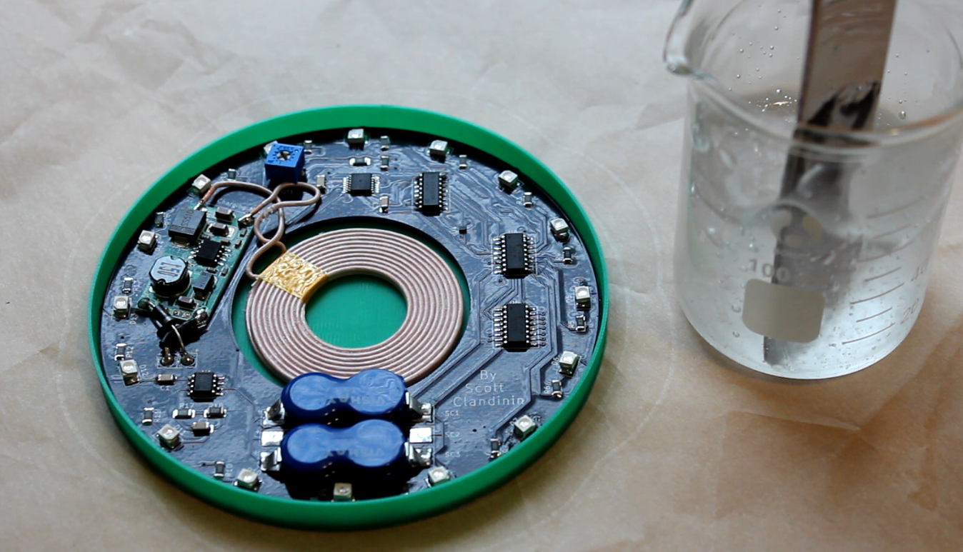
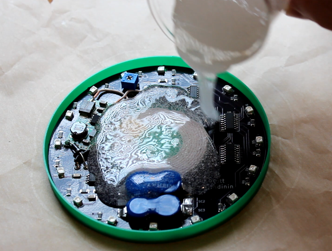
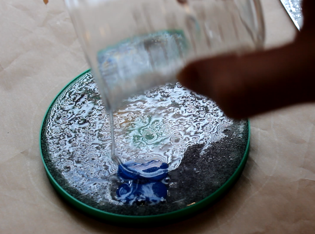
- The coaster is hermetically sealed in casting resin making the device impervious to spilling liquid or condensation. The encapsulated design also protects the coaster components from drops.
Is it a product that could succeed in the market?
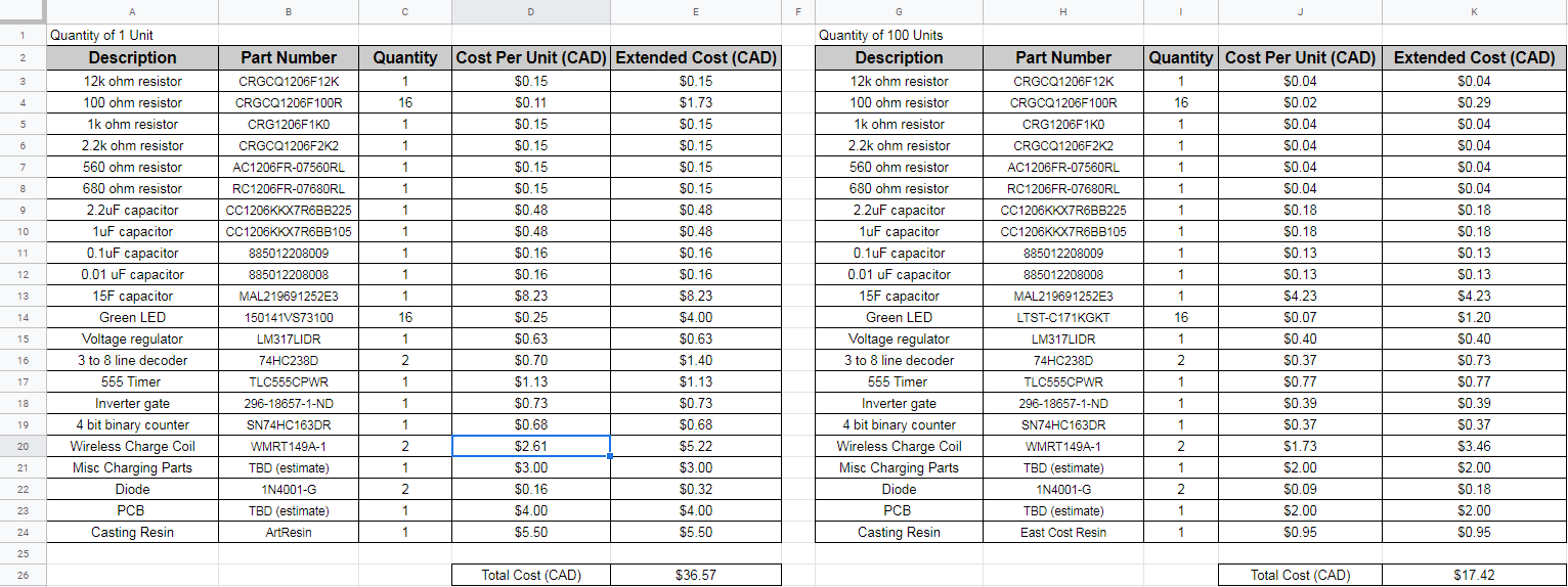
Though more expensive than some other options in the market, there exist features that justify a higher price point. The feasibility of such a product in the market would hinge on optimizing the design and production to bring the price to a desirable level.
What is planned for future revisions?
-Increasing energy efficiency.
-Decreasing cost by looking at more cost effective components and designs.
-Smaller, more customized footprint to allow for a slimmer design.
-Removing 3D printed coaster base, allowing the full coaster to be held in casting resin.
-Optimization of production process.

 From left to right: Coaster body, charging base top, charging base body, charging base bottom.
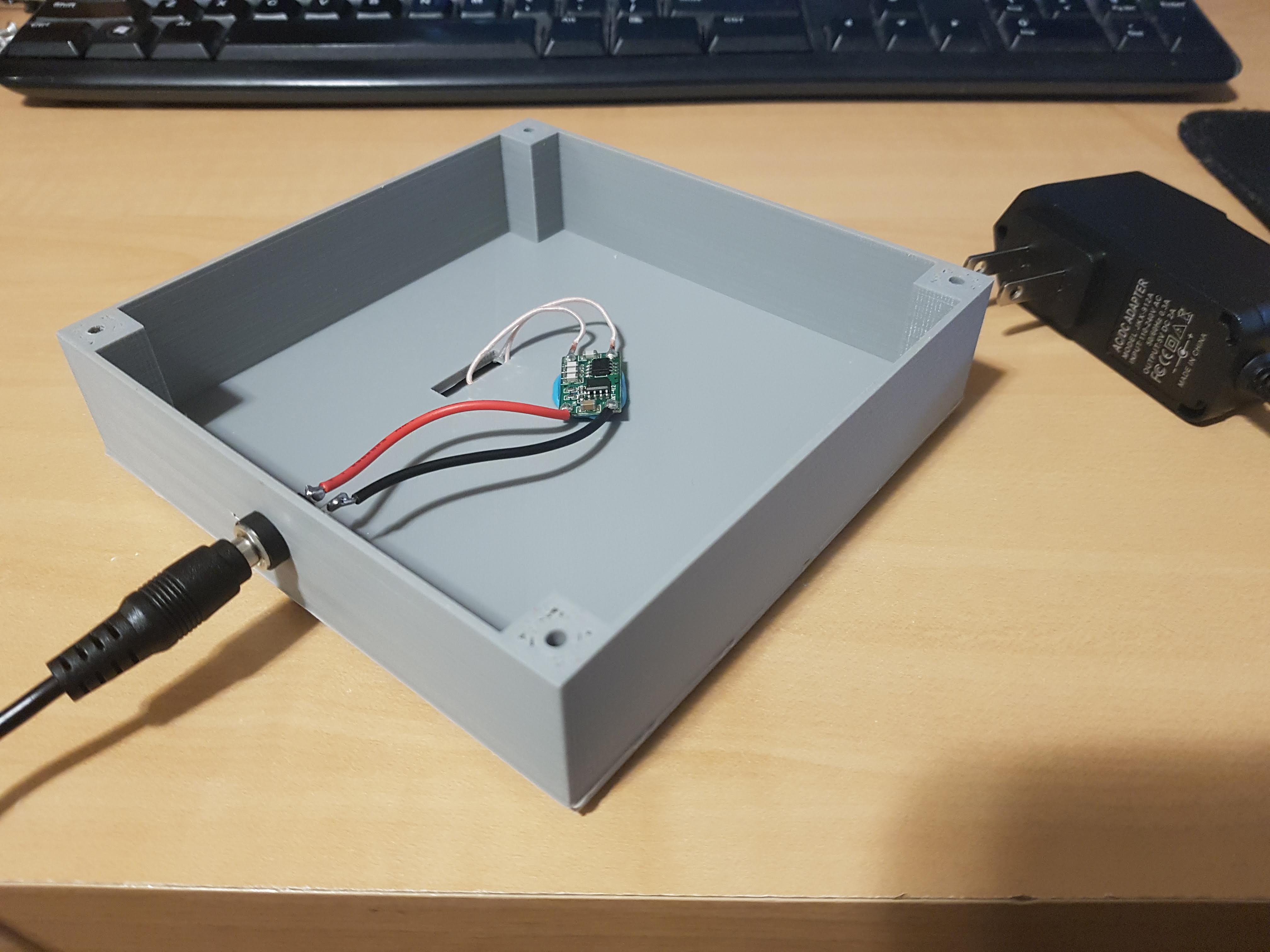


 Peter Fröhlich
 Said Alvarado Marin
 DailyDIY
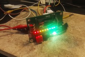
 Luke
Luke
This is really cool and similar to a project I've been working on. Adding a reed switch to turn the device on and off could be a useful feature to add and could even be used to with a microcontroller to switch between preset patterns.