 Peter Fröhlich
Preface
I do not like being wasteful and throwing something away just because it is damaged.
Things need to be build with the possibility of maintaining it, planned obsolescence and DRM are not the road to a better world.
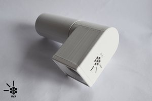
This little project aims to build something that can be repaired, improved and maintained.
Without any glue, only screws are used, this light can be torn down in a matter of seconds.
It uses a rechargeable battery that has been upcycled from broken notebook battery packs and it does not use proprietary connectors or cables.
It is designed to be as efficient as possible, so not much energy is wasted, the LED's have a comparably high lumen per watt ratio and with a switching boost regulator the waste energy is kept lower then with a linear driver.
Everyone can build the main parts for it with a simple and cheap 3D printer, this new technology has the capability to change the world we live in.
With open the source design everybody can print replacement parts in a matter of hours.
And while it is not the best material, when printing in a biodegradeable thermoplasic like PLA (polylactic acid) we can reduce the impact on the amount of non recycleable thrash.
The electronics have been build with reasonably large SMD components so they can be easily reworked and replaced and the integrated circuits are intentionally not leg-less.
I have chosen packages with exposed metal or legs for easy probing and repair ability.
While this flashlight is fully working it still is more a draft then a prototype, there are many things that need to be improved.
But the main problem faced at the moment is the destructive testing of the electrical components.
The driver circuit board is not particularly expensive but in the process of testing, more then one will be destroyed.
For this a test bench has to be designed and build to measure the current and voltages at different nodes to characterize the circuit and over all efficiency.
And a debug firmware and the software for the data acquisition of the test bench has to be written.
There are many other challenges as well.
- Ordering proper circuit boards for the LED and Driver.
- Creating a bed of nails for programing and batch testing.
- Creating a small level shifter board or shield to program this with a regular Arduino acting as a ISP programmer.
- Overhauling the cooling of the LED, with additional metal, hopefully recycled material as well.
- The whole body needs to be redesigned.
- The button mechanism needs improvements.
- A proper firmware needs to be written.
- Further down the road i would like to simplifiy the driver circuit itself or have multiple versions available.
- As well as an option to use more common LED's.


 The efficiency of the circuit is rather poor at the moment, this is mainly caused by the bad, single sided layout and bad ground routing and should be improved by 10% to 15% with a proper board layout:


 Said Alvarado Marin
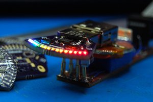
 zakqwy
 Michael
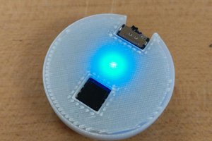
 Ben Lim
German over engineering!