 Ben Lim
I discovered the box breathing method on http://quietkit.com/box-breathing/. It has its roots in Yoga and can even be found in the Navy Seals. It is said to be effective in enhancing focus and promoting well-being and I have found this to be true personally. On occasion it has also helped me and others to defuse high anxiety situations. I then decided to make this device because I didn't want to stare at a screen to reduce possible distractions and eye strain. I wanted to be able to pull something out of my pocket and begin the cycle immediately.
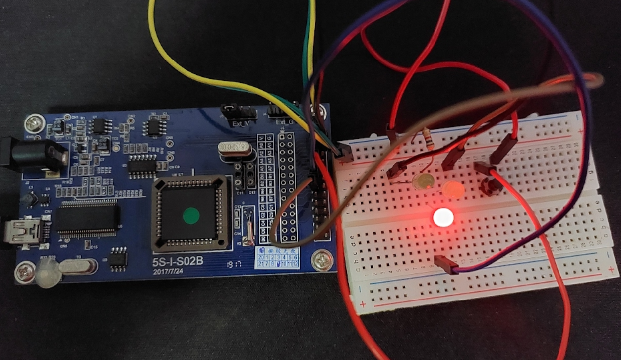
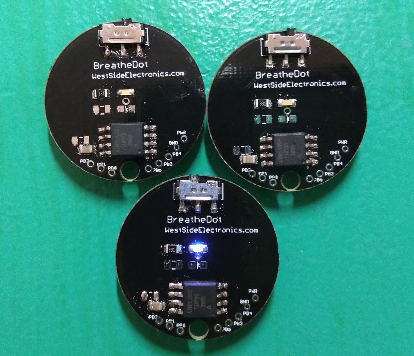
I used an ATTiny85 to program it because initially it was what I had on hand. That turned out to be a good choice because it allowed me to run different programs and prototype different designs quickly without changing the hardware.
It is fun to fiddle with and nice to look at. A case of white plastic helps to soften the glow of the blue LED and keeps the electronics safe.
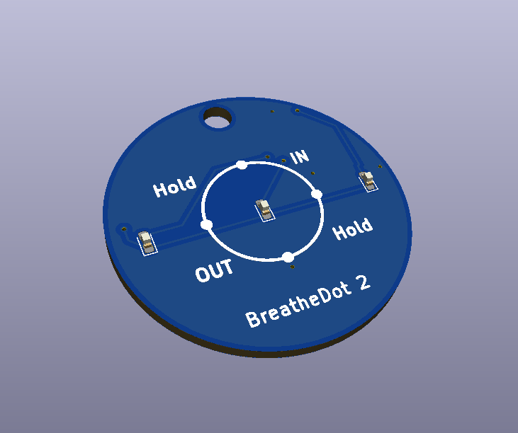
The LED follows a cycle of brighten (breathe in), lit (hold), dim (breathe out), off (hold). In order to indicate a change visually, gamma correction is provided for the PWM output of the LED because the human eye is not sensitive to changes in bright lights. A RGB version also fades from color to color that provides a visually appealing effect in addition to an increased perception of change.
Once this project is complete I will release the files and show you how to put the project together yourself. However do note that these are SMD parts so you might have to salvage a few parts yourself like resistors and LEDs. You can also buy them from Digikey for a few cents each.
All code, documentation and design on these project pages are licensed under the GNU General Public License (GPL) unless otherwise stated.
Comments? Questions? Ideas on how to improve? I'm always happy to talk in further detail about the design considerations. Just leave a comment below.
Currently I am working on a new version. There is an option of purchasing some on Tindie for those who want to experiment with one without going through the hassle of putting one together.


 Peter Fröhlich
 Sander van de Bor
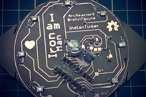
 Rohit Gupta
 OK Design
If I programm the attiny while its not soldered to the board do I need the vias for PB0 - PB5 and PWR?