0%
0%
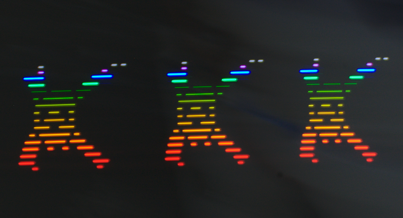
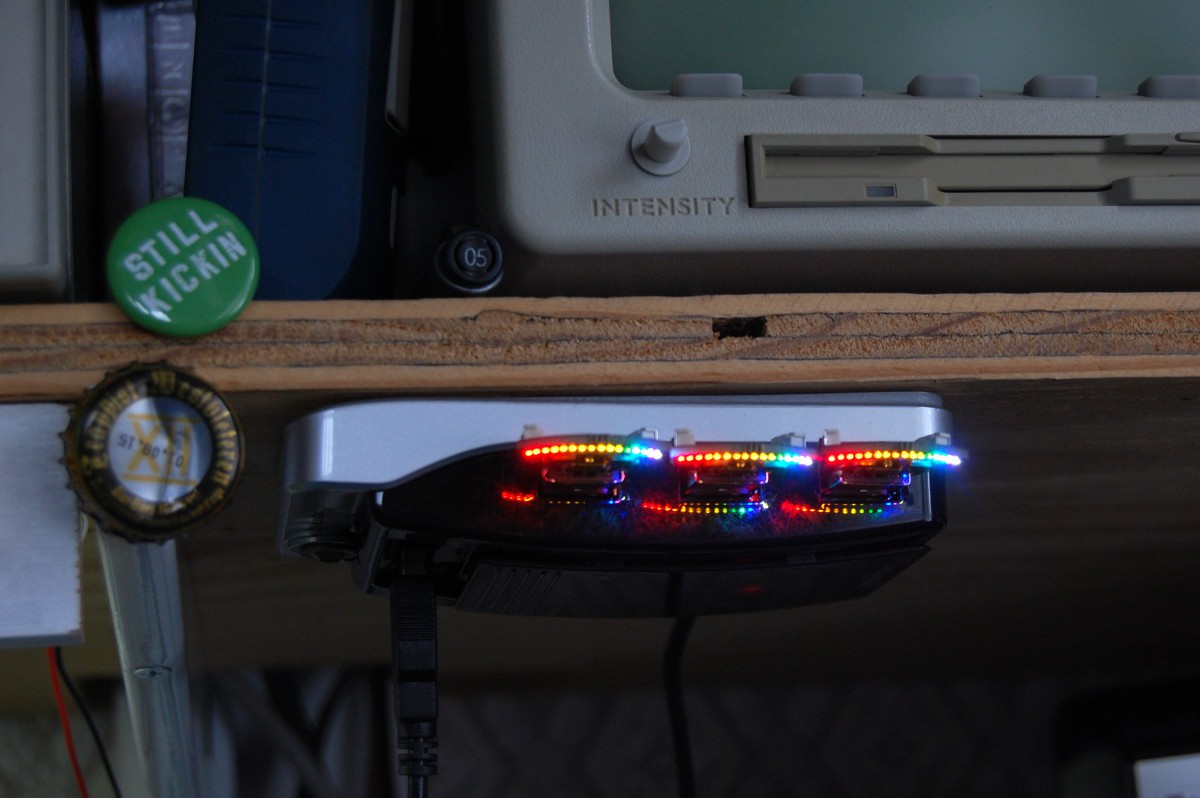
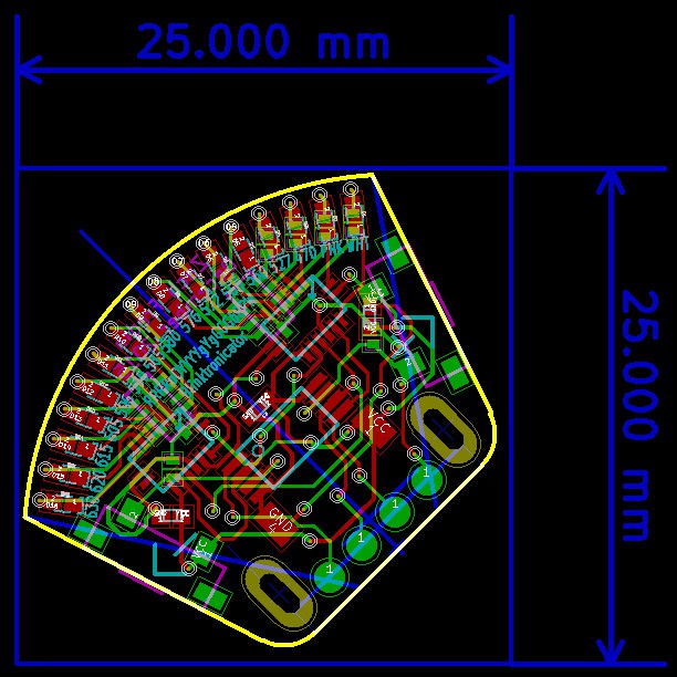
blinktronicator
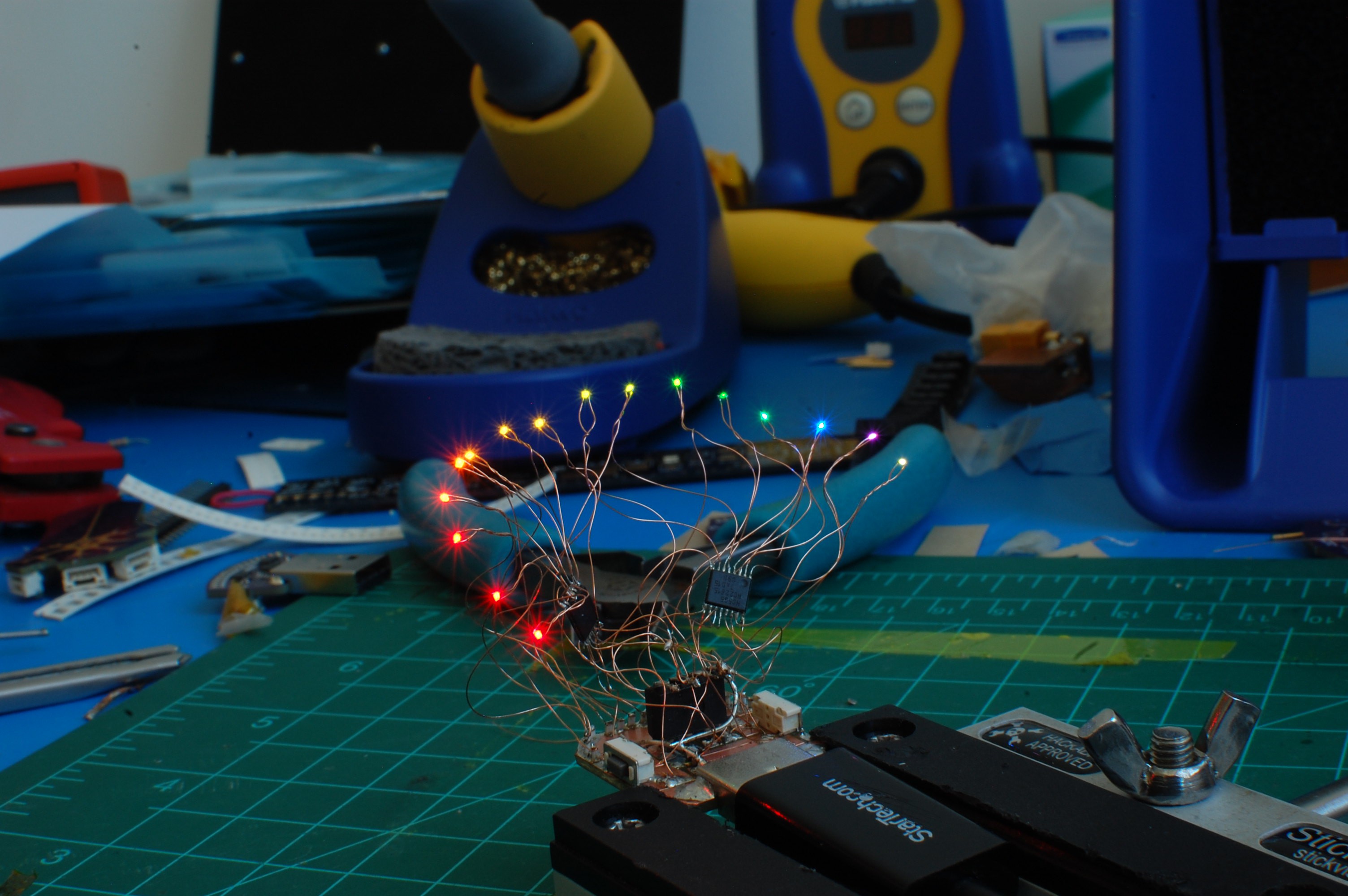
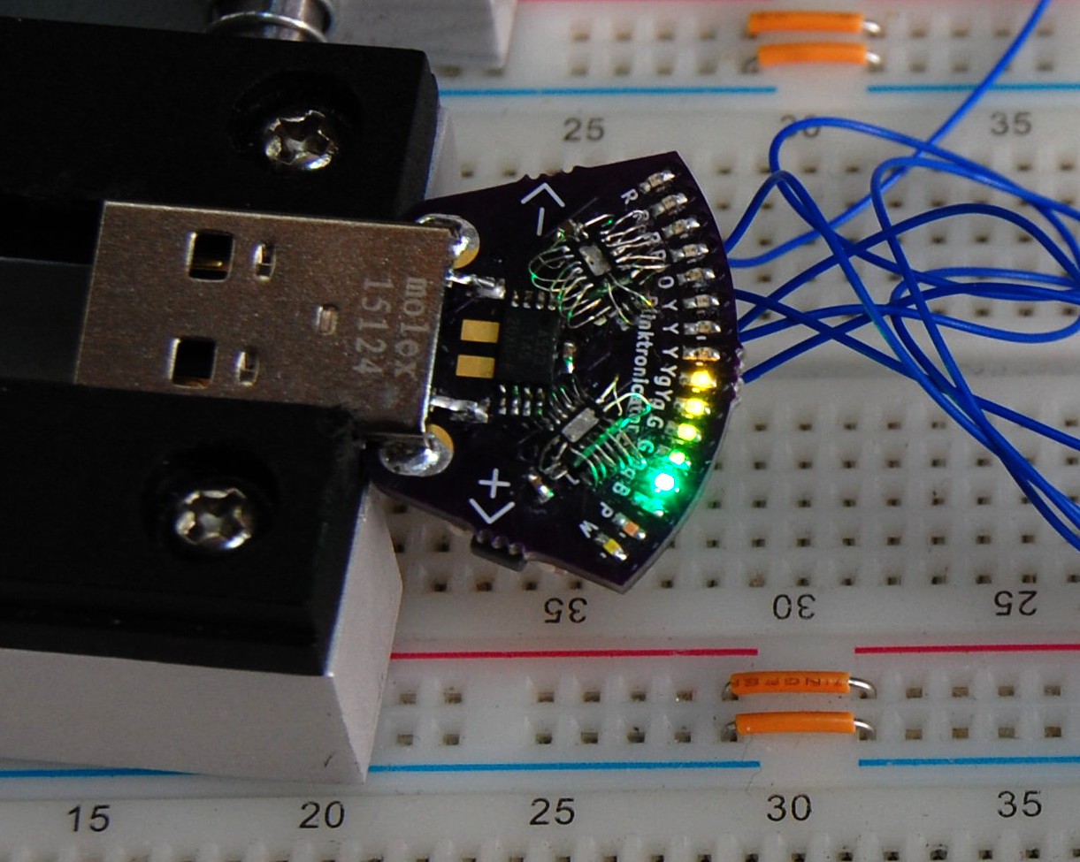
Sixteen different LED colors on a teeny tiny board.
 zakqwy
Become a Hackaday.io member
Already have an account? Log in.
Just one more thing
To make the experience fit your profile, pick a username and tell us what interests you.
Pick an awesome username
hackaday.io/
Your profile's URL: hackaday.io/username. Max 25 alphanumeric characters.
Pick a few interests
Projects that share your interests
People that share your interests
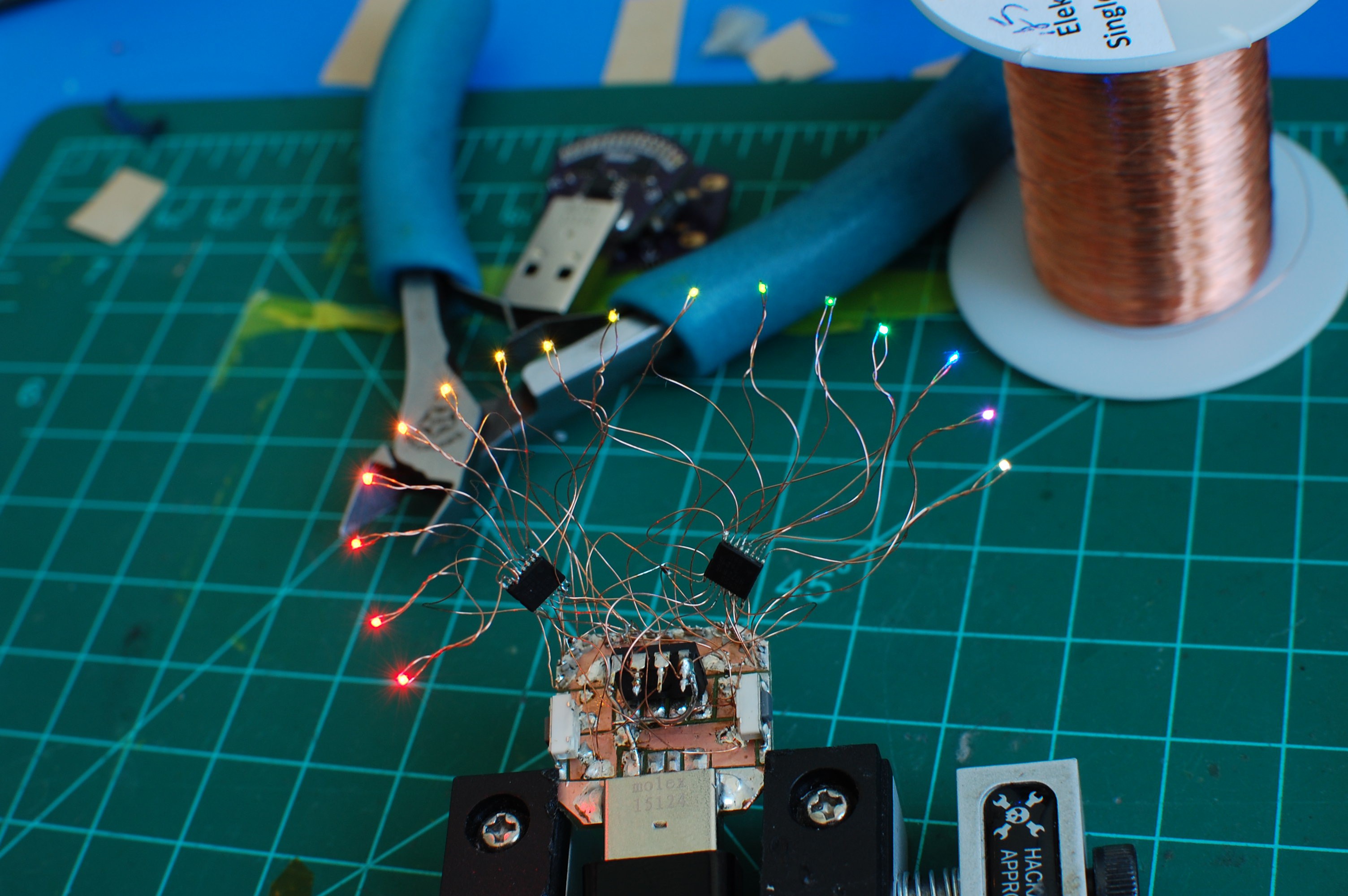
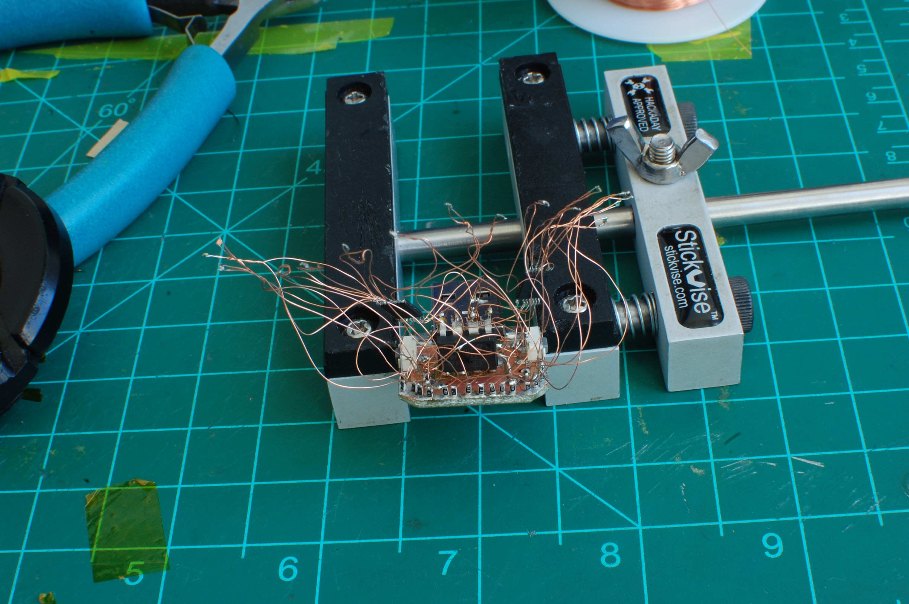
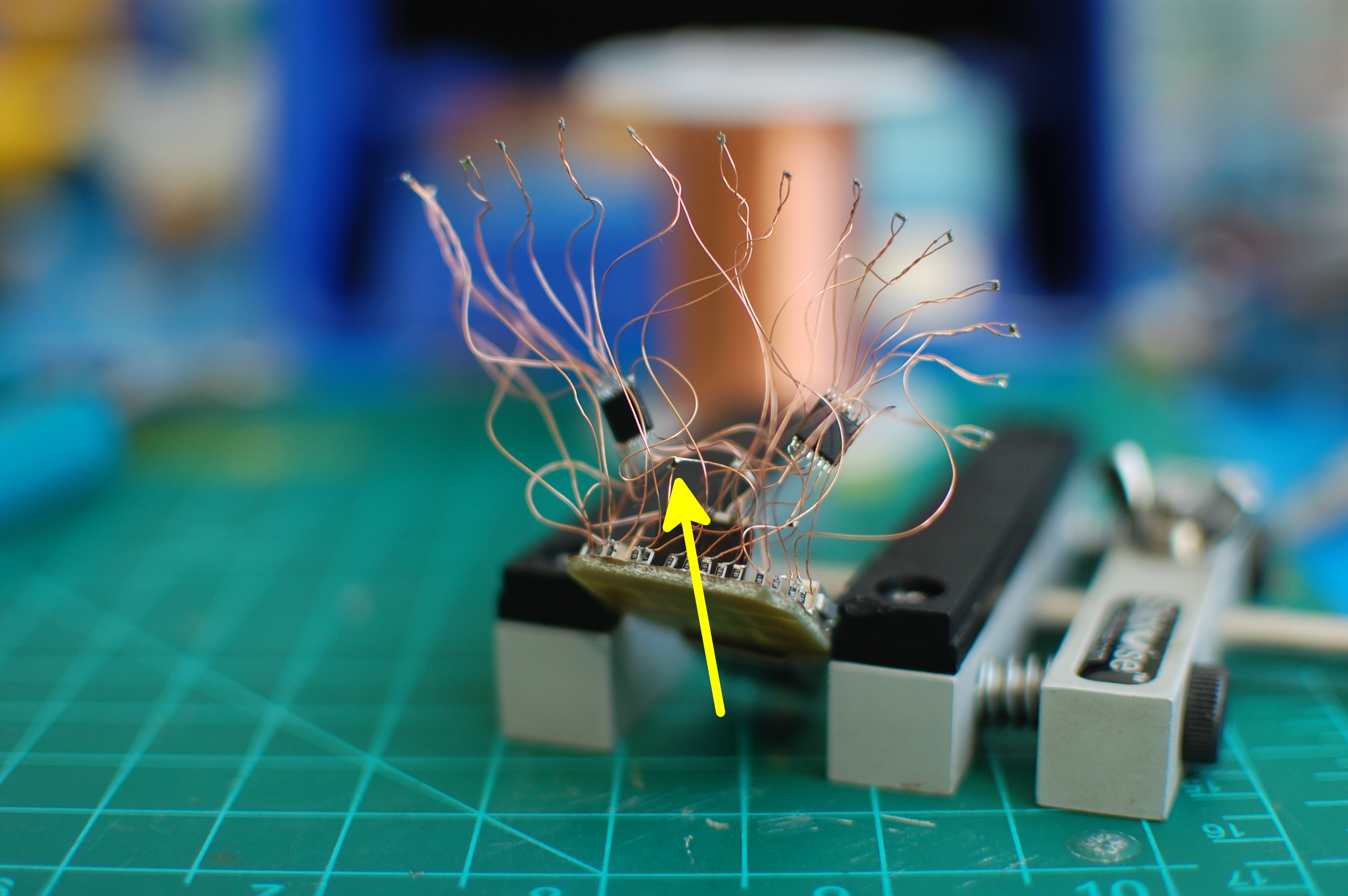
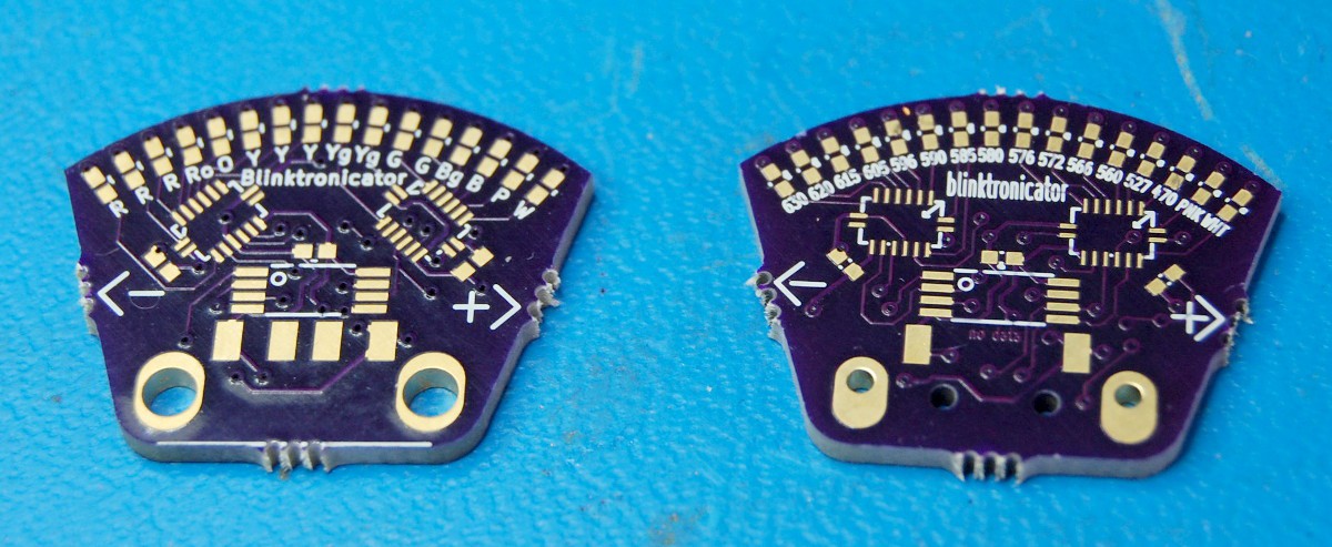
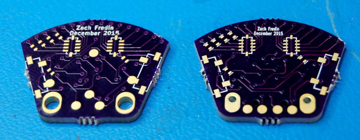
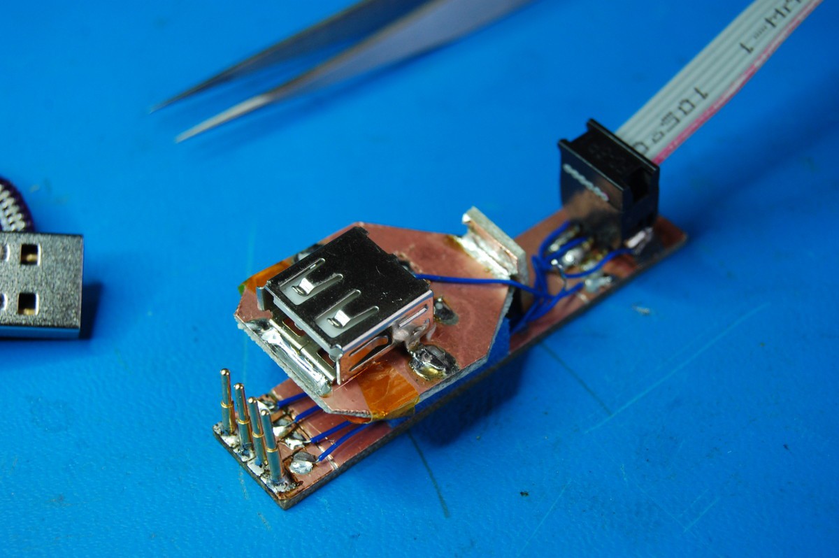


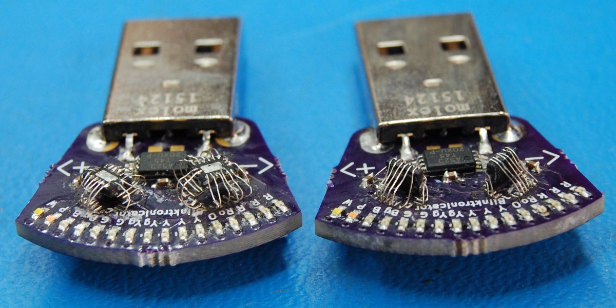
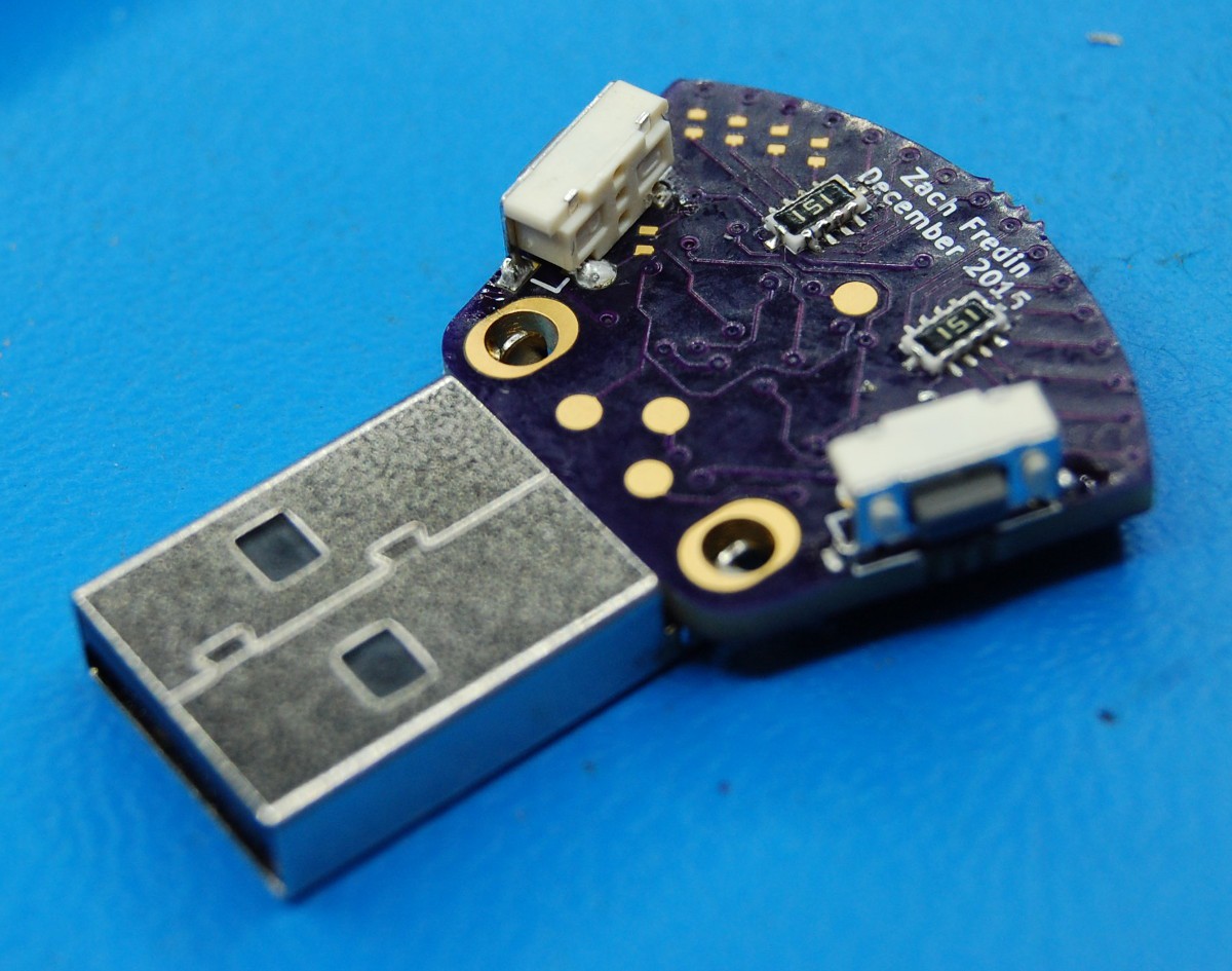
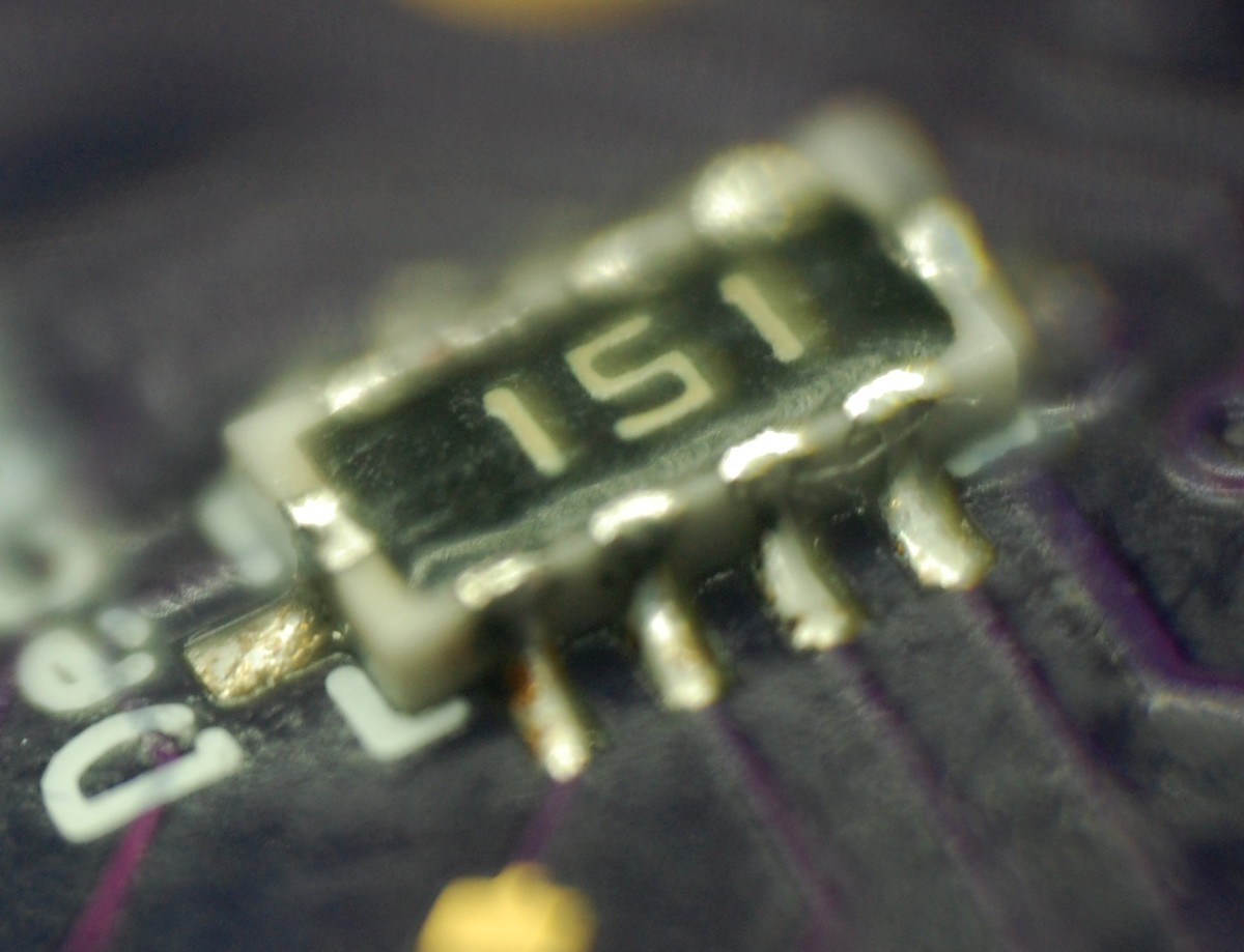
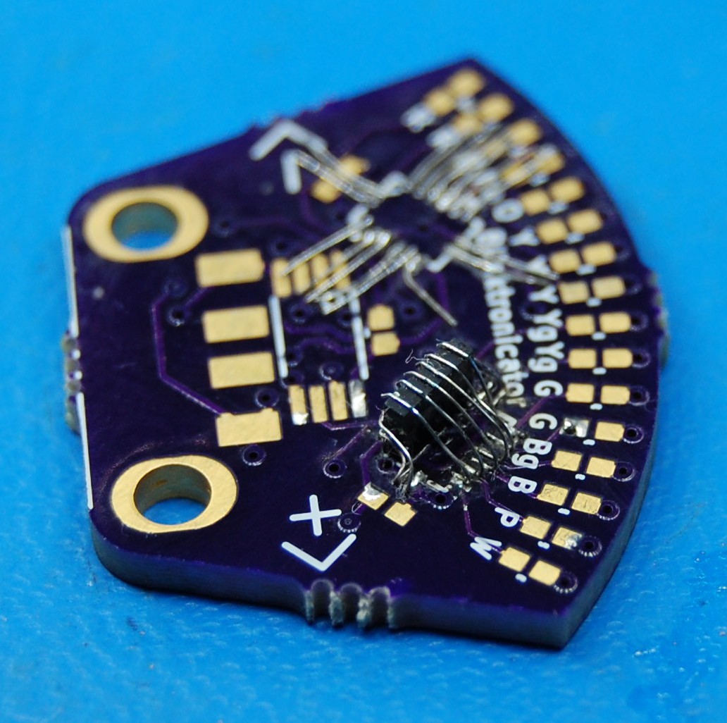 I enjoyed avoiding six point-to-point solder connections. Securing the chip first was a big plus, too--the previous method required a few extra steps and was difficult to get right on the first (or second...) try. The four side connections were, once again, the most difficult part of the operation.
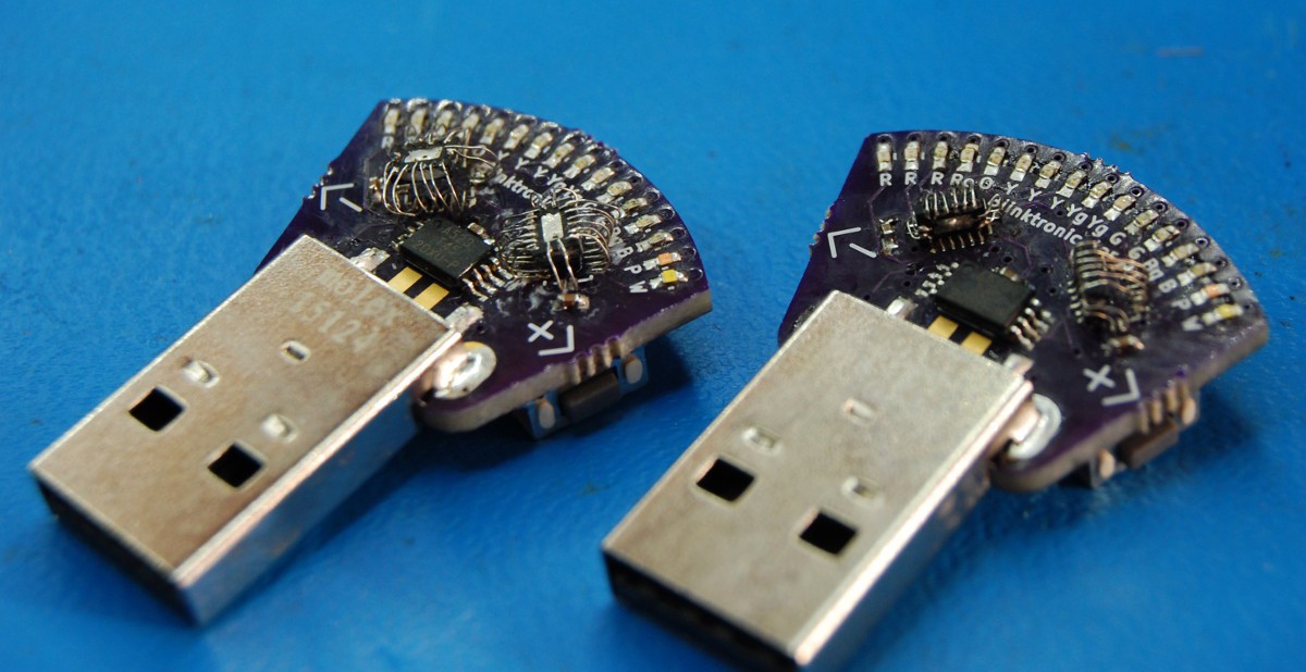


 Mike Szczys
 Andy Geppert
 Kevin Arne
 Christoph
You somehow inspired this : Testing the Rainbow LED extension board
https://hackaday.io/project/16542-electronics-workshops-resources/log/53631-raspberry-pi-educational-boards