 John Loeffler
The goals of OPEN Power is to produce 3 final Prototypes. All Power Supplies will have USB Charging of Lithium polymer batteries and a Load Sharing and Uninterruptible power when disconnected.
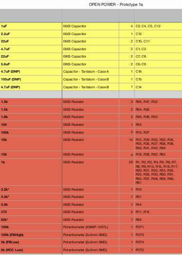
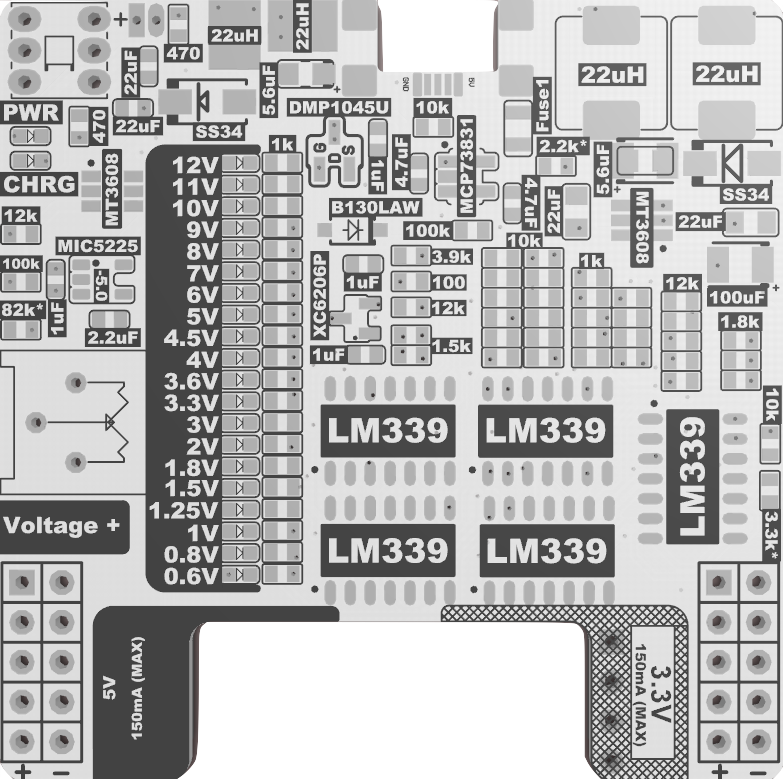
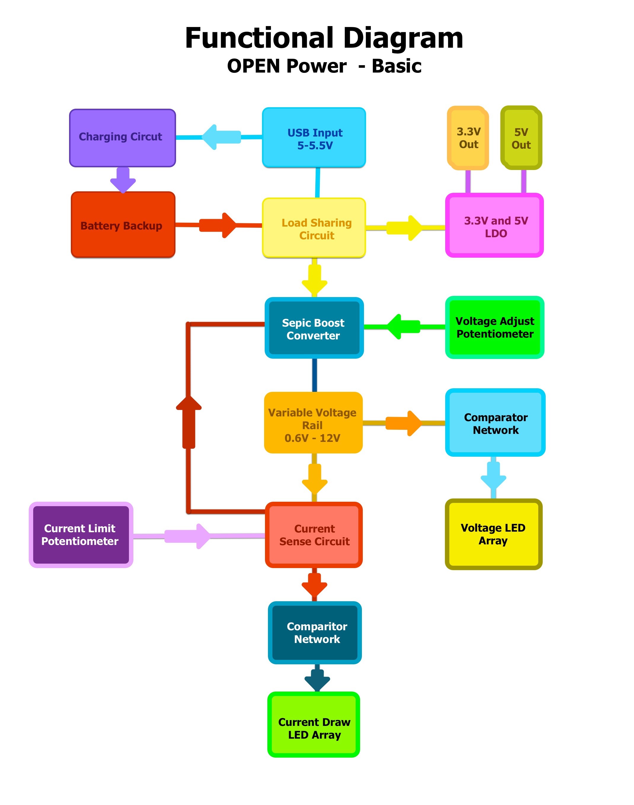
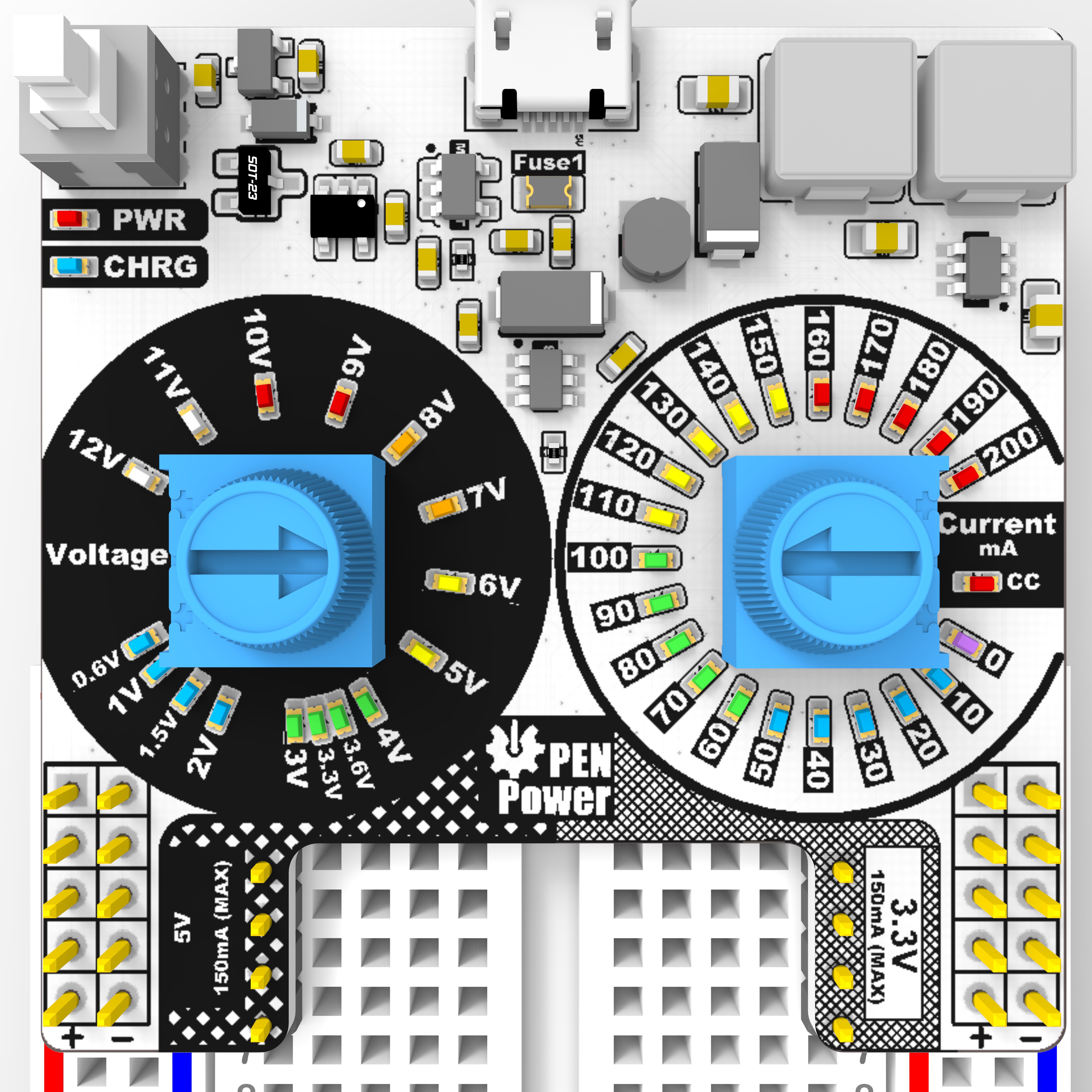
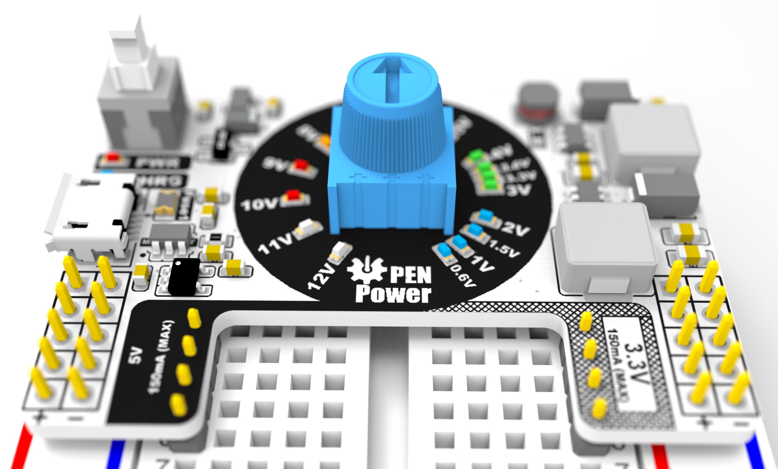
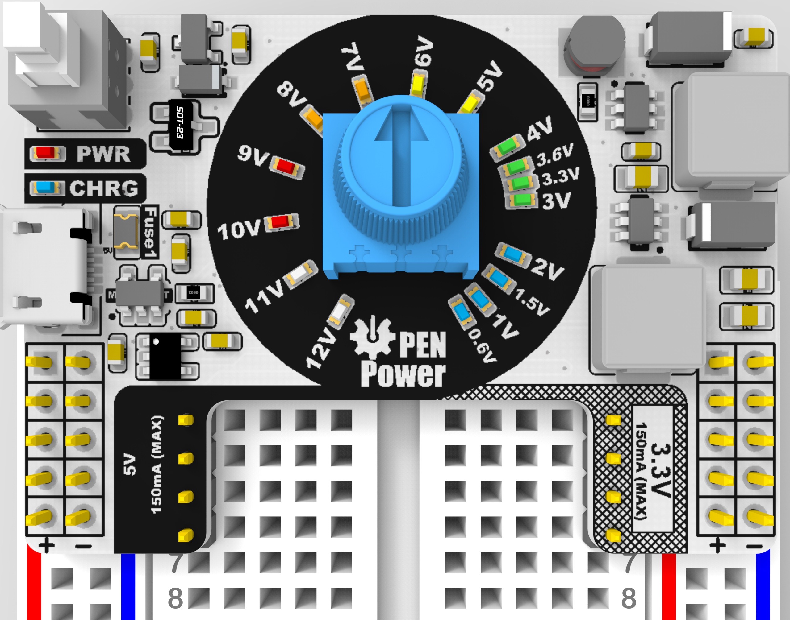
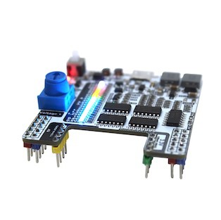
| Prototype 1A: Simple Constant voltage Power SupplyVariable from 0.6V to 12V. Will Include 5V and 3V Rails. Voltage indicator will be achieved using comparators and LED Array. This was chosen to reduce cost as much as possible and keep each board with components under $2.75. -------------------------------------------- Status (COMPLETED)  |
   |
    |
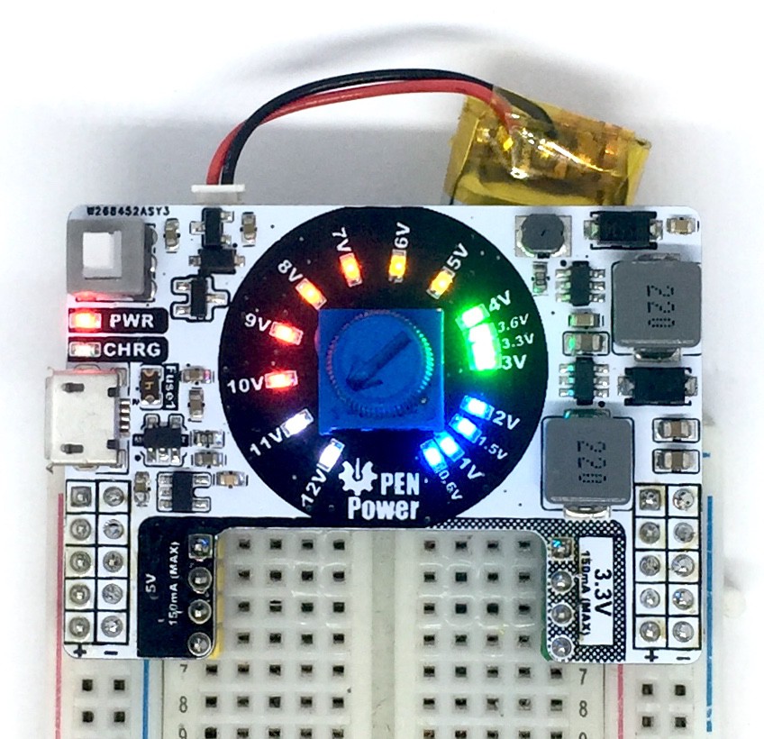
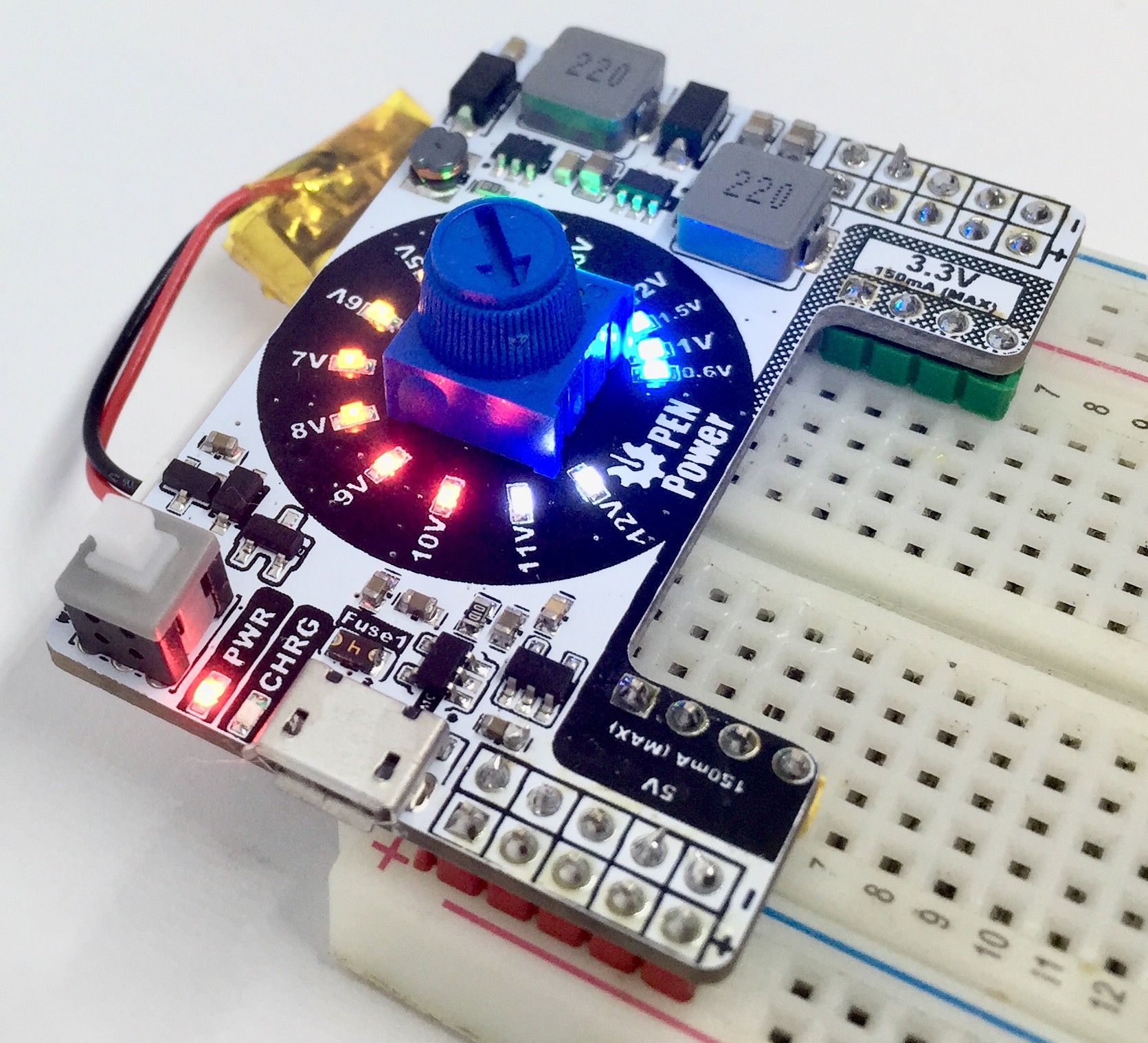
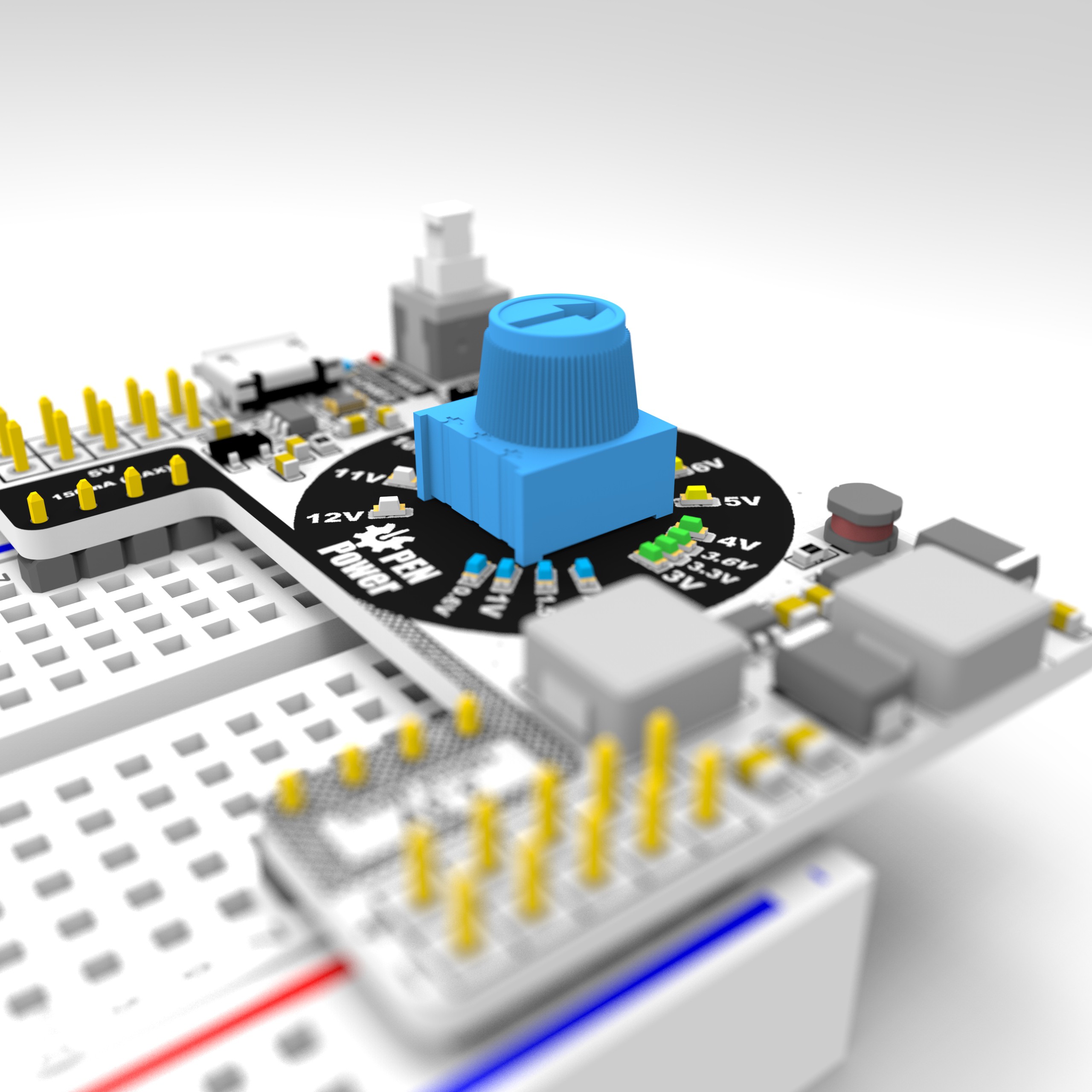
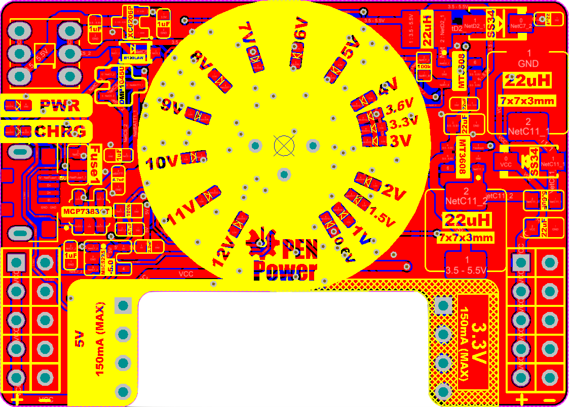
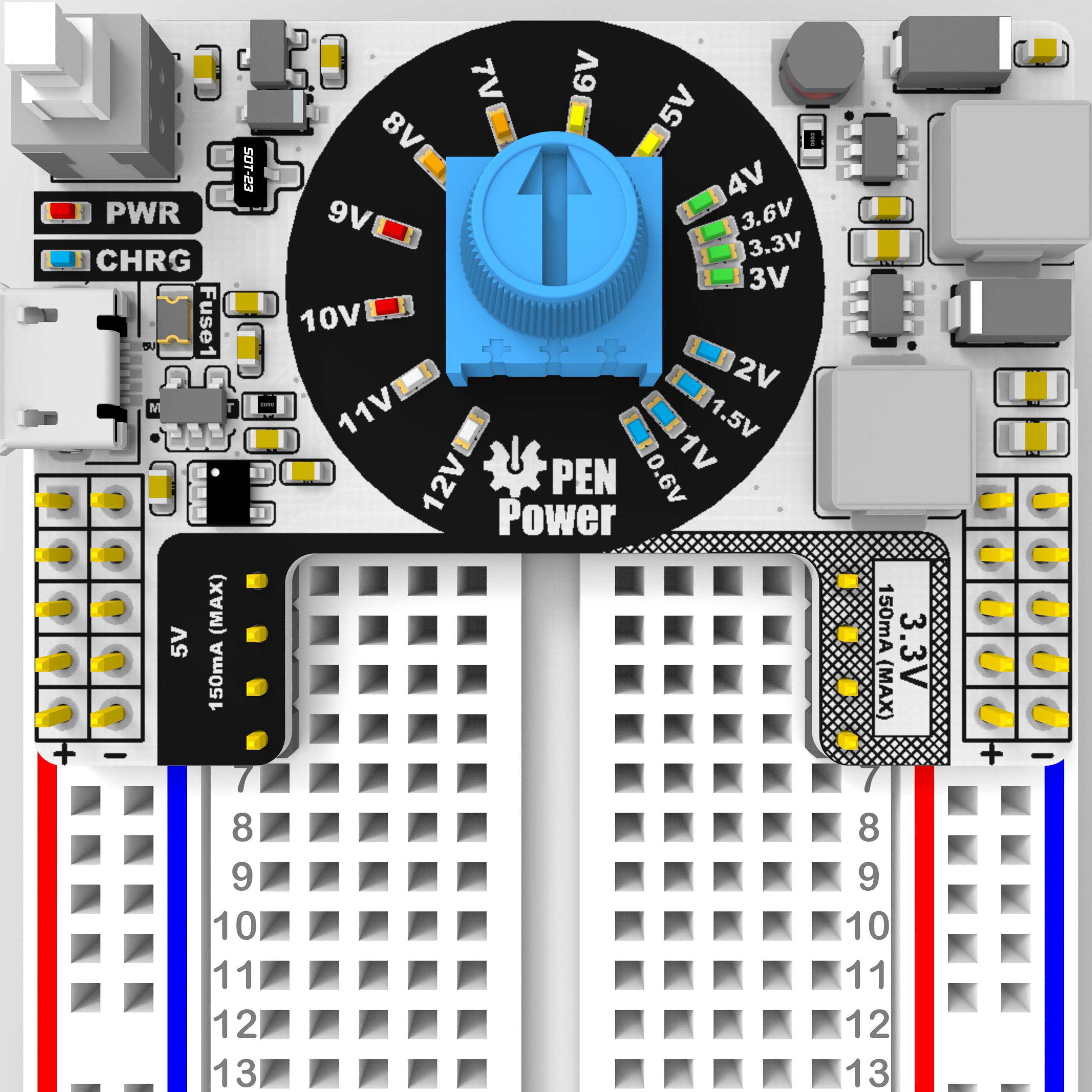
| Prototype 1B: Revision 1B The Led arrays are switch from a linear array to a polar array around the Voltage and Potentiometer trimmers have been added to calibrate. ---------------------------------------------------------- Status (COMPLETED)  | BOM (LINK)   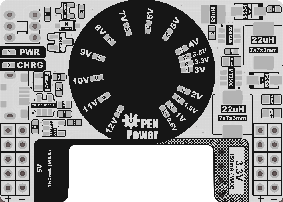
 |    |
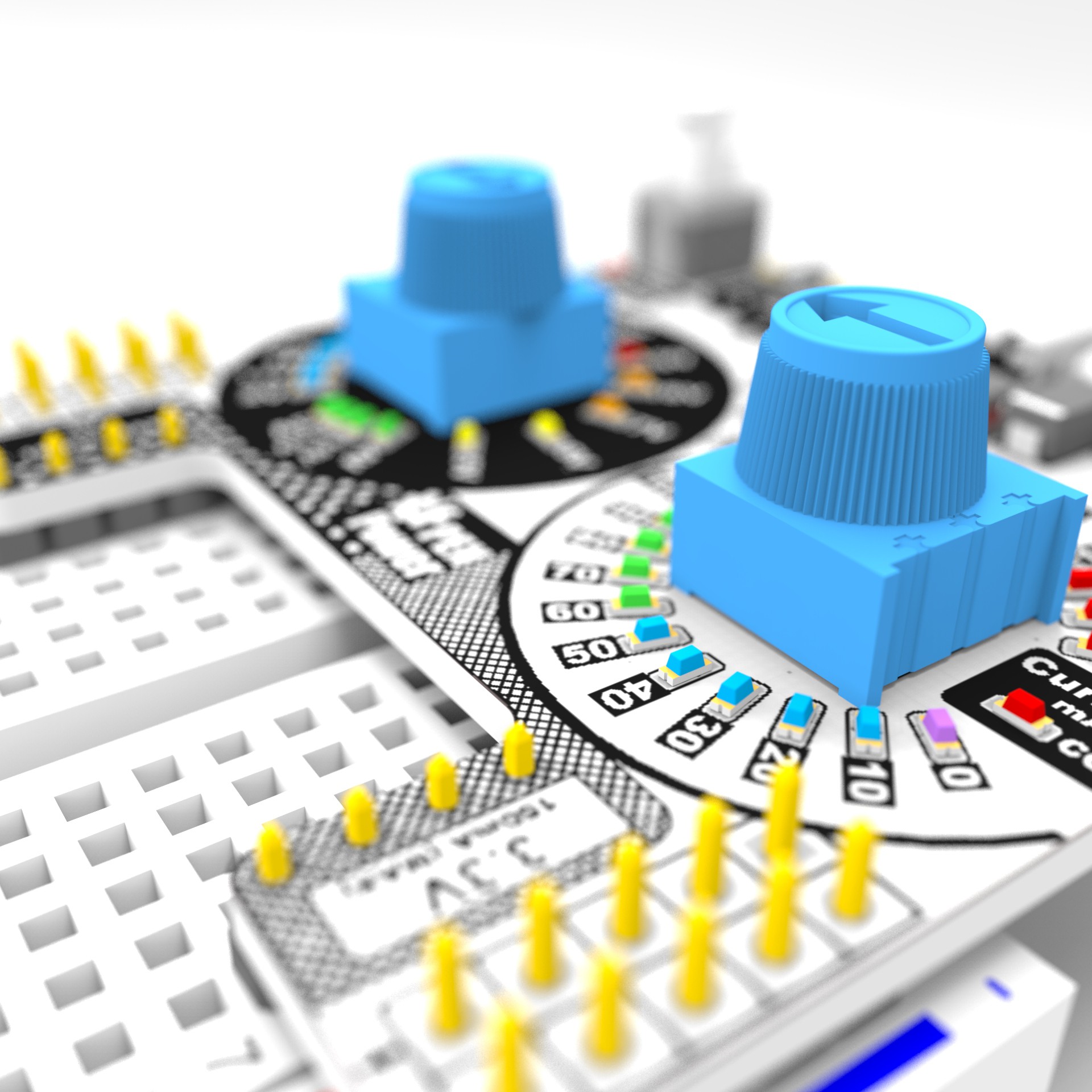
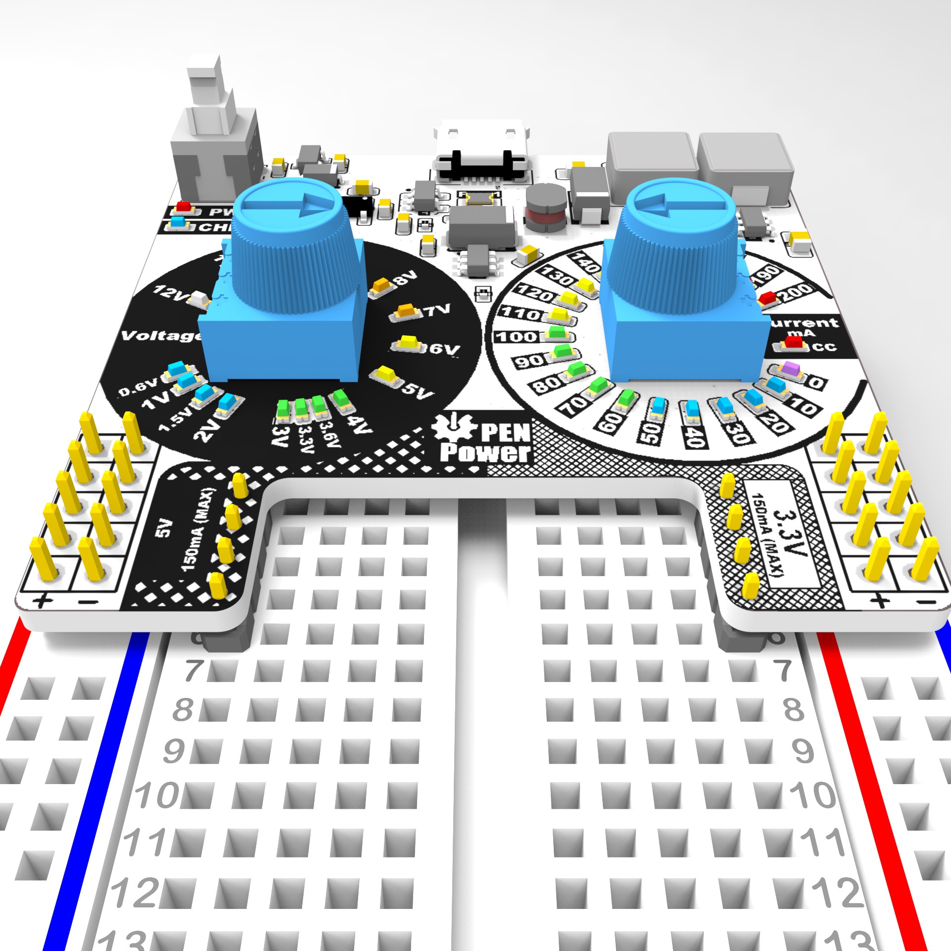
| Prototype 1C: Revision 1c will add an additional Constant Current Knob to allot user to limit current and see around what current is being drawn (10mA Increments). ---------------------------------------------------------- Status (Sent to FAB)  | BOM (LINK) 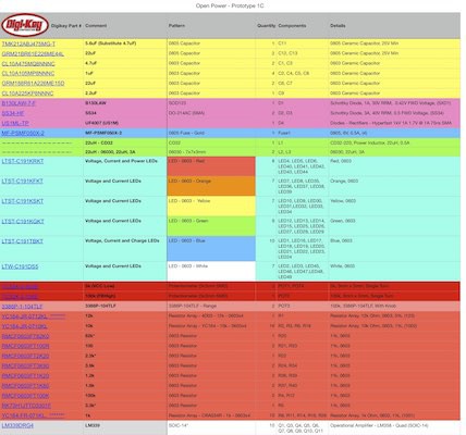 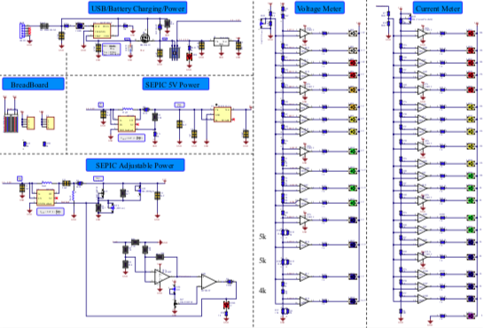 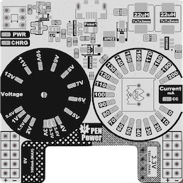 |    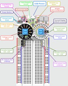 |
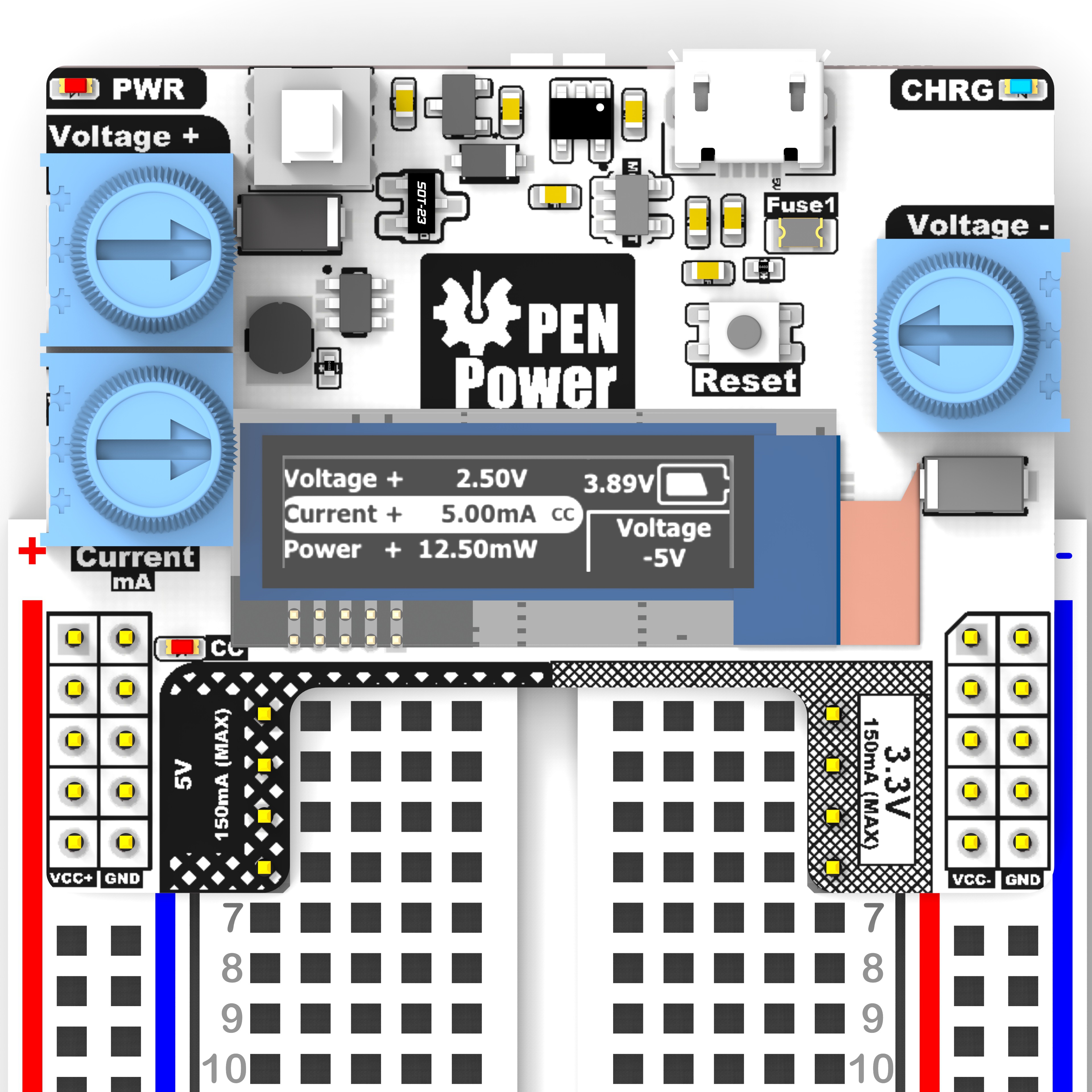
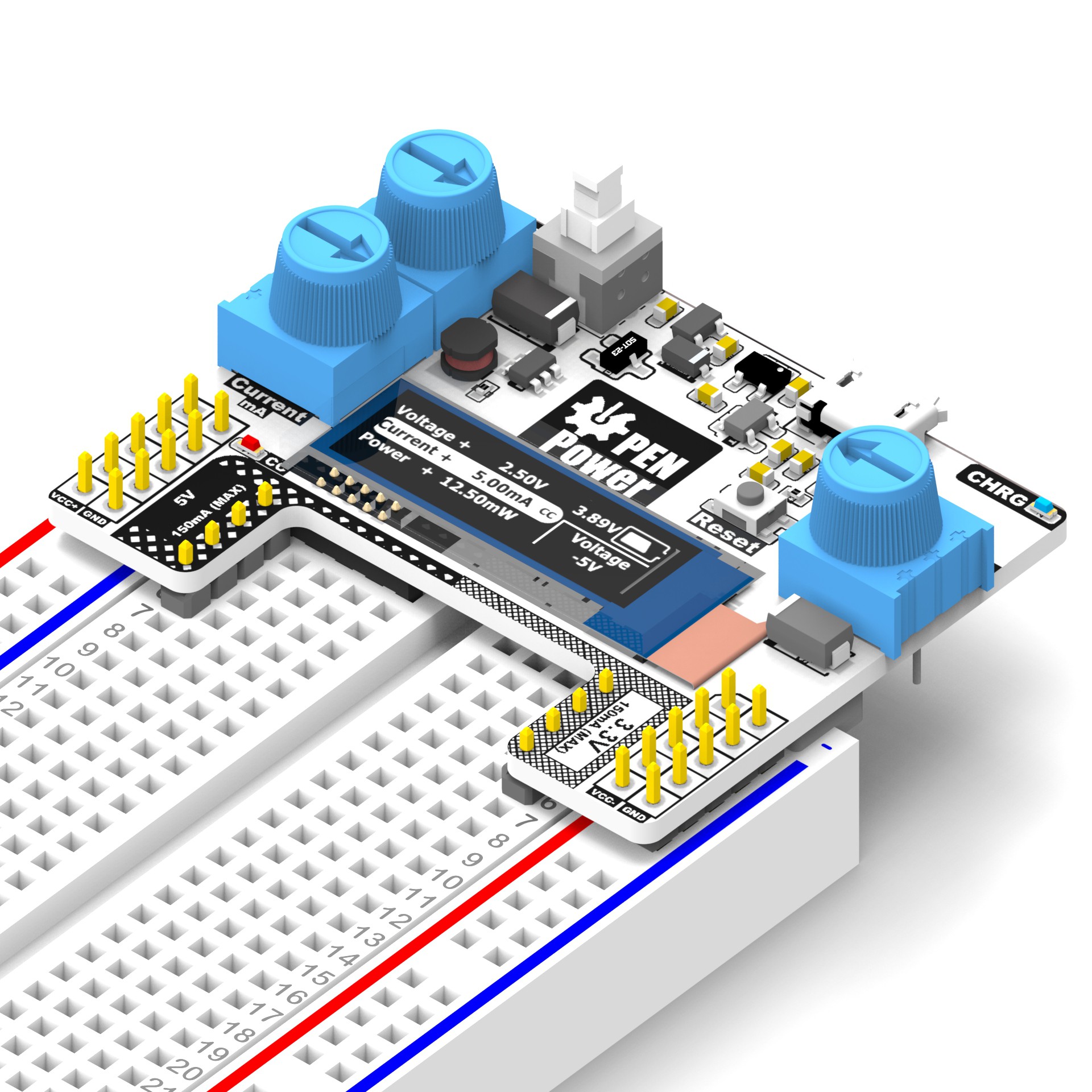
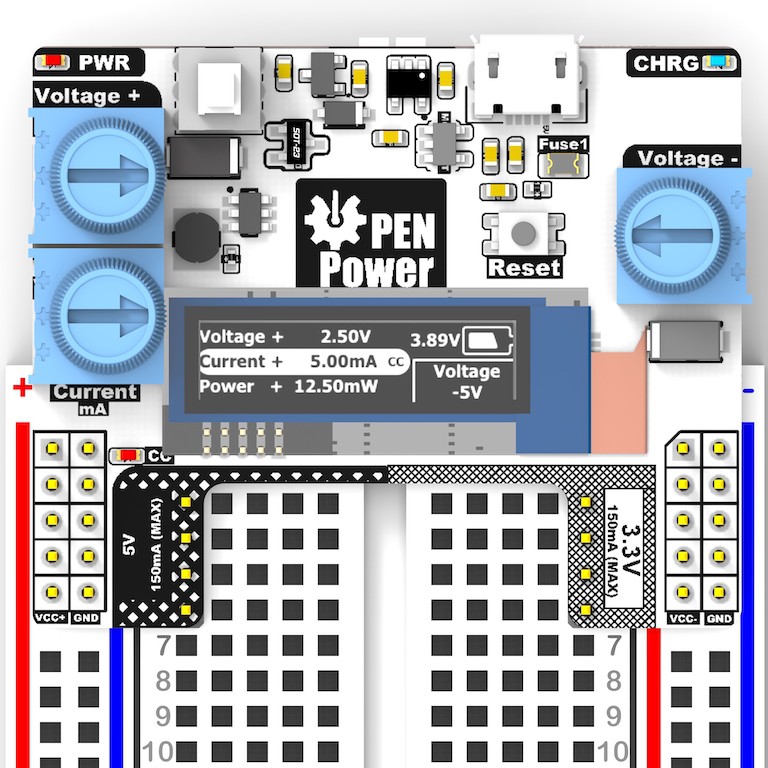
| Prototype 2A: A Constant Voltage Constant current Power Supply 0.6V to 12V. In addition to an adjustable Negative Rail. Voltage, Current and Power of thepositive Rail will be displayed on a compact OLED. Negative Rail Voltage will also Be displayed as well as the Battery Voltage. ---------------------------------------------------------- Status (Layout Mock-up) |   | |
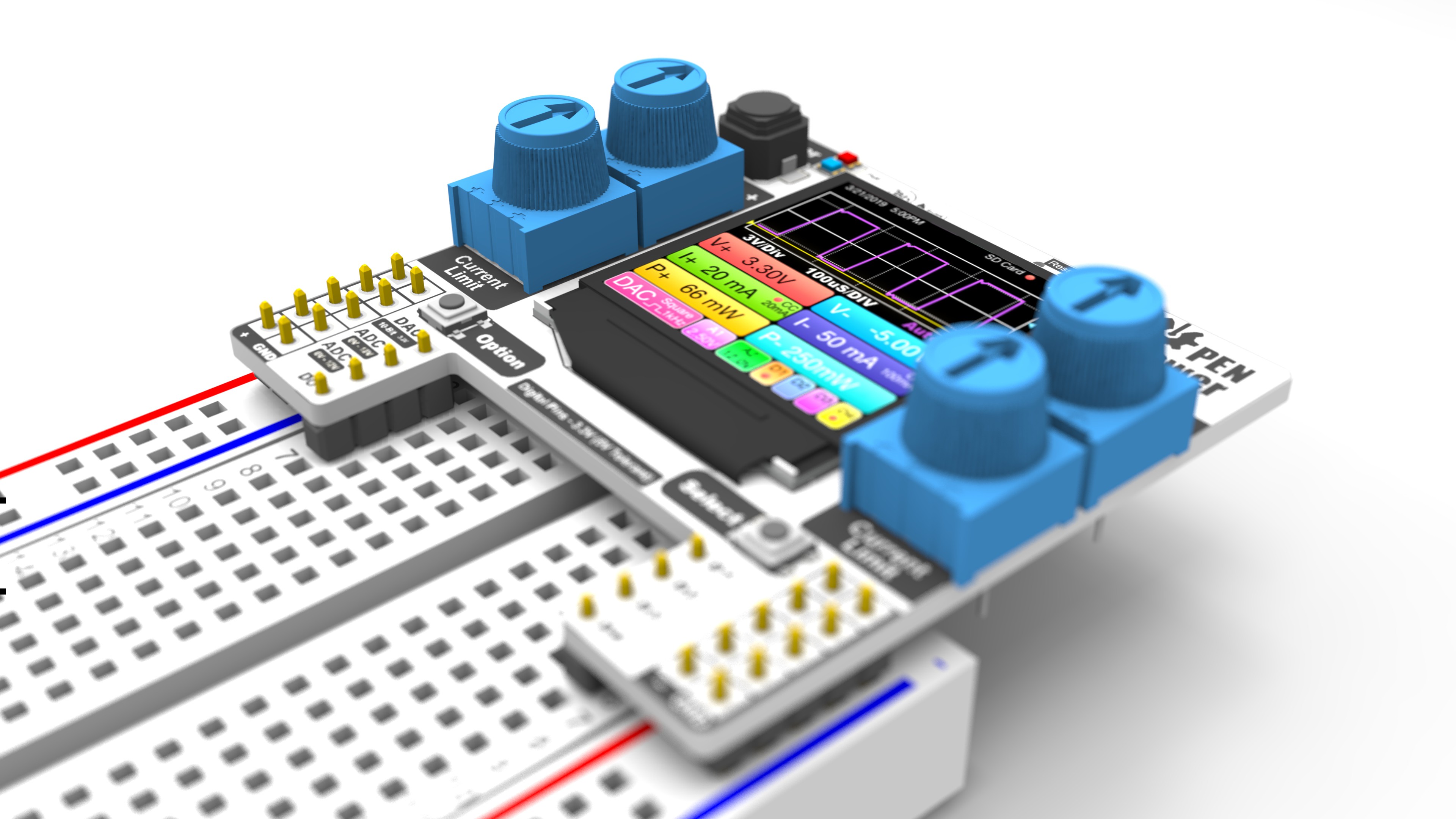
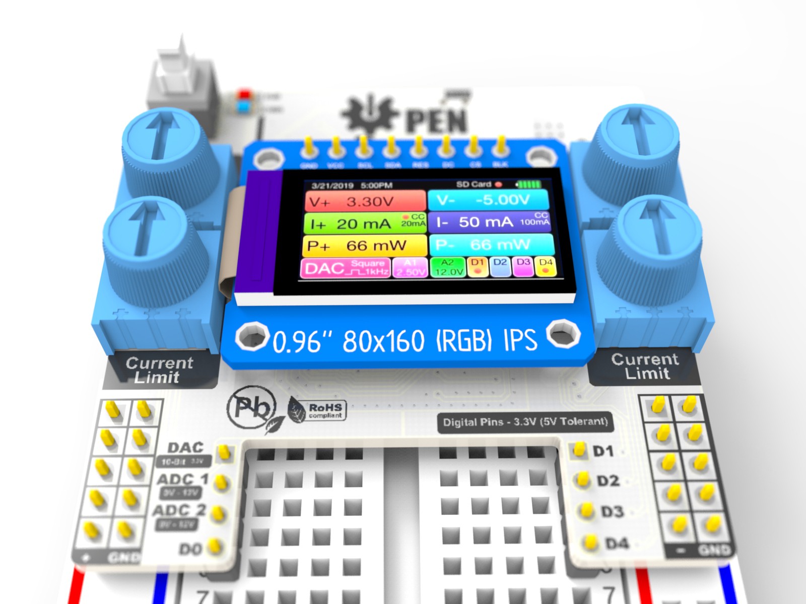
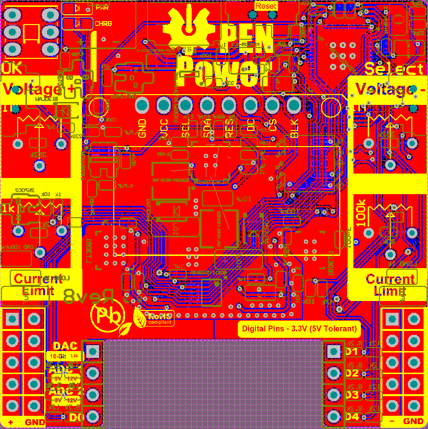
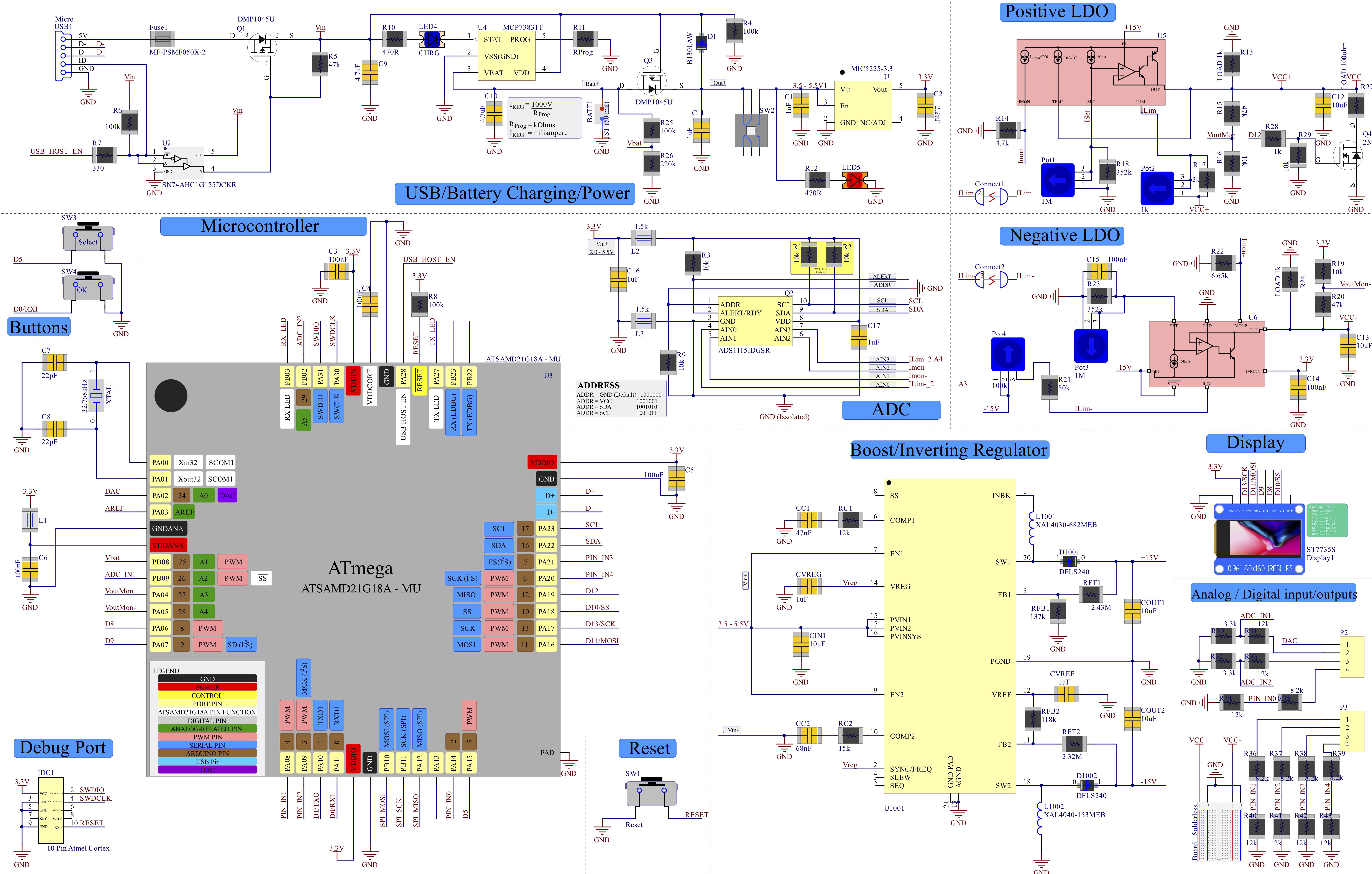
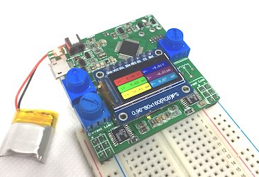
| Prototype 3A: Utilizes a Boost Inverting IC to get +-13V and LDO's to Reduce the Voltage between 0 and 12V. Both +- Rail Voltage, Current and Power will Be displayed on a Full Color 0.96" LED Display. ---------------------------------------------------------- Status (COMPLETED)   | Schematic (LINK) 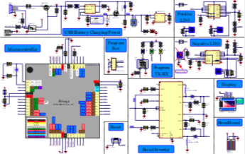   |     |
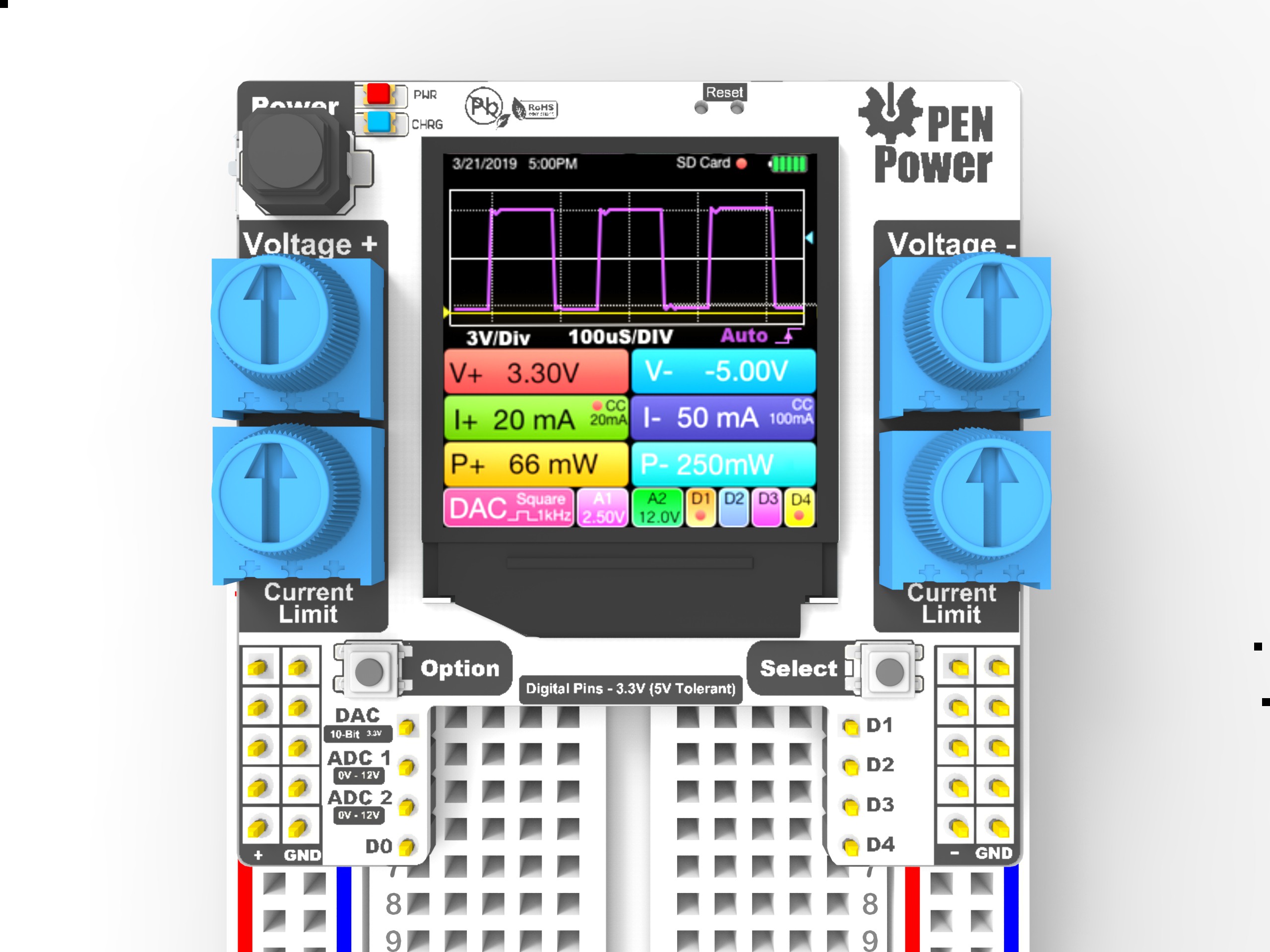
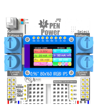
| Prototype 3B: Revision 3b will have a DAC Output, 2 Analog input and 4 DIO Pins. The implementation of a 16-Bit ADC Will improve the Current Readout ---------------------------------------------------------- Status (Sent To the Fab 8/28/2019) Update - design Errors made and sent back to the fab | Schematic (Link) 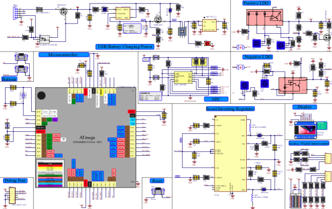 |   |
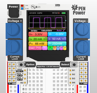
| Prototype 3C: Revision 3c will switch from the Samd21 to the Samd51 for faster Processing power and additional IOs. The LCD will also be upgraded to a 1.3" IPS 240x240 LCD. Since the circuit is completely analog the MCU can perform Double duty and Potentially be used as a Crude Oscilloscope or Logic Analyzer. |   |


 Lithium ION
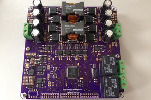
 Nathaniel VerLee
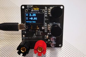
 CentyLab
steper up-down from
0-24V ? AA, 18650 , AAA, 9V etc.