 Daren Schwenke
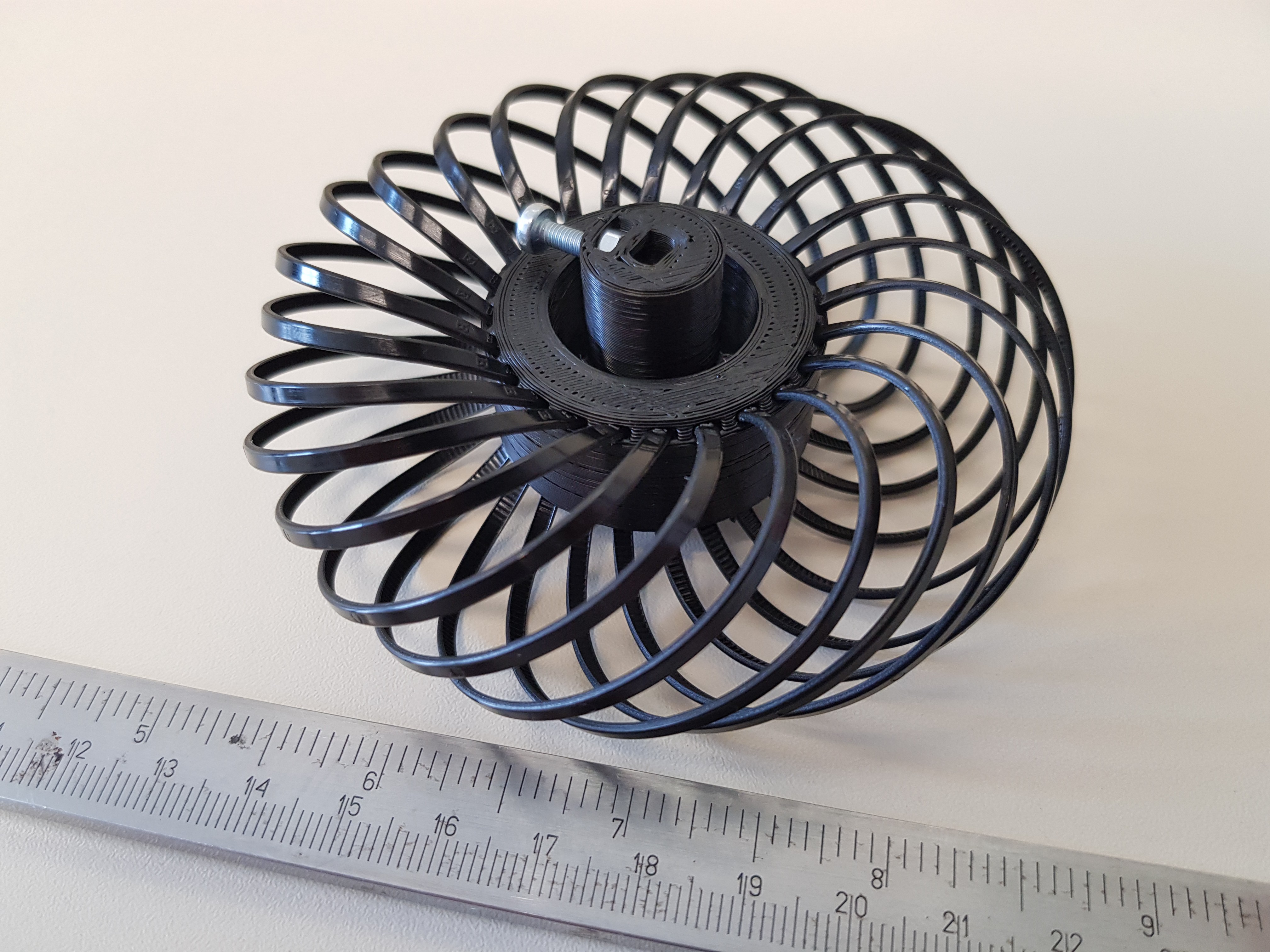
Mecanum wheels are one way to allow a robot to move in any direction. The general premise is that rotation always produces a force which is at a 45 degree angle to the axis of the wheel. By varying the direction of rotation of the wheels, you can move in any direction including sideways.
The downside here is that Mecanum wheels are relatively expensive, to the point that I've never used them.
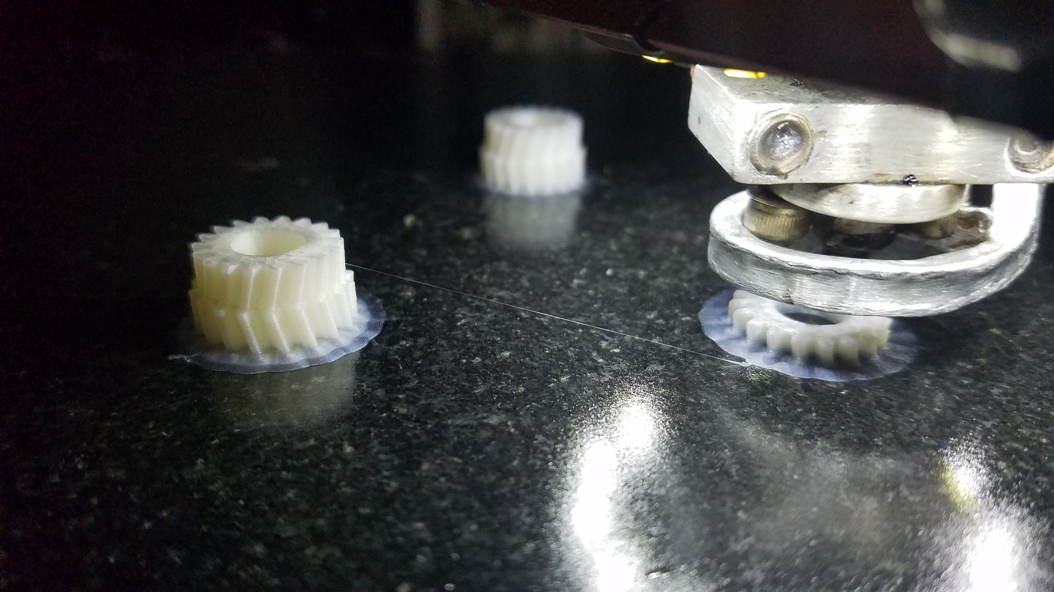
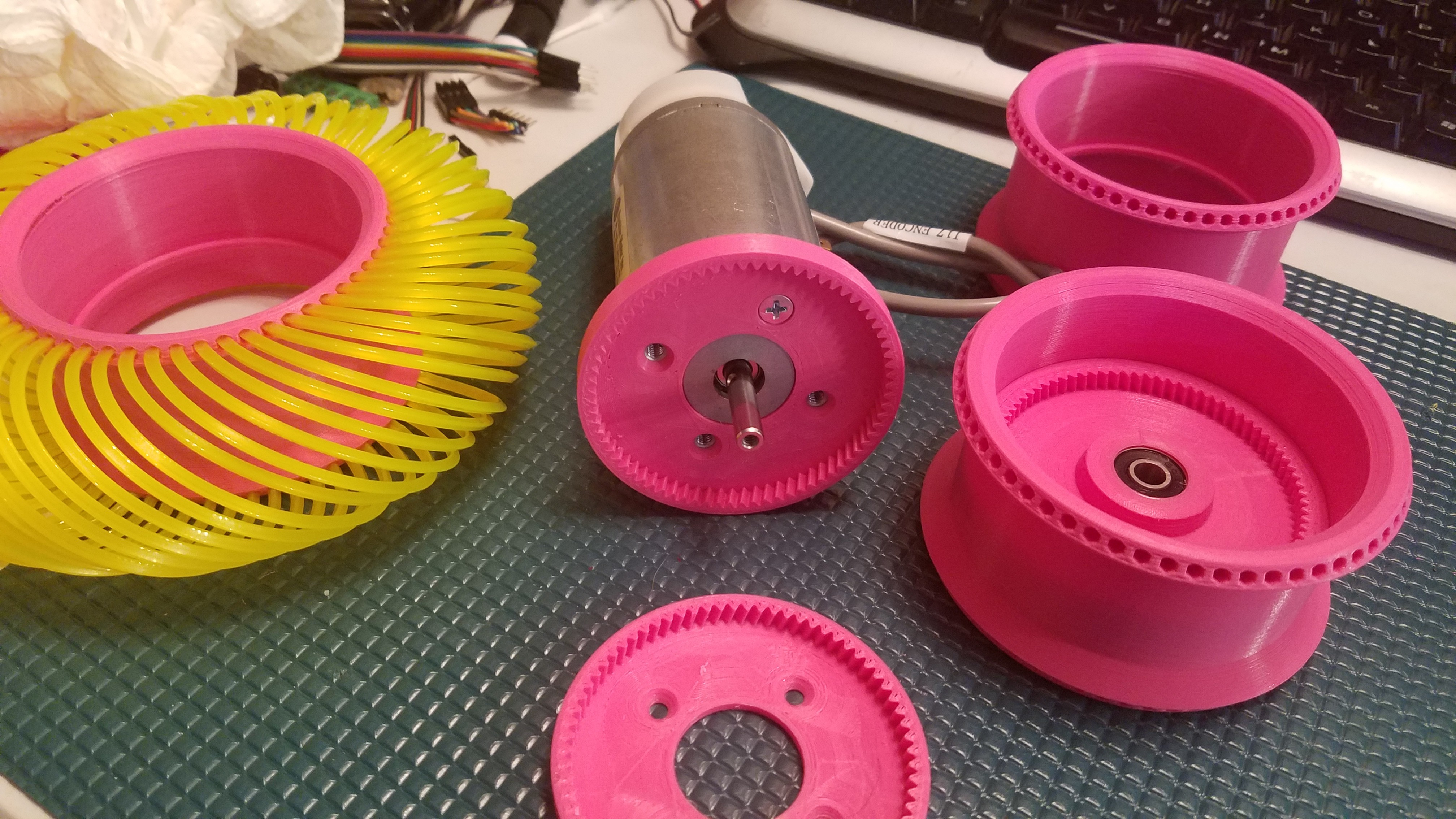
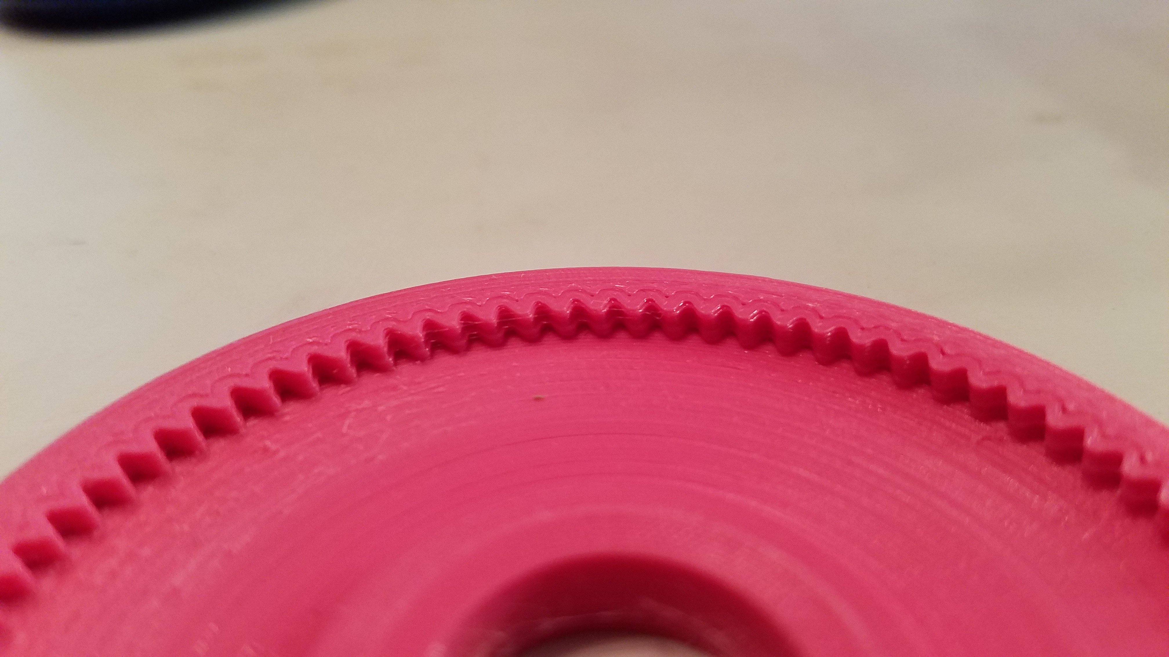
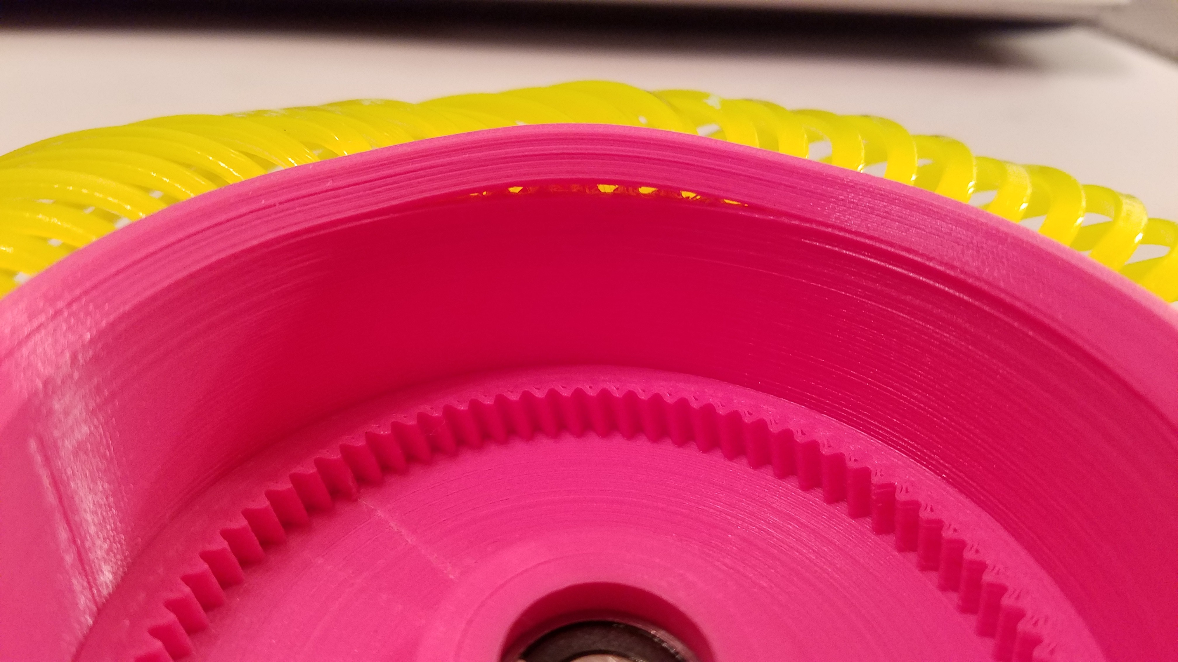
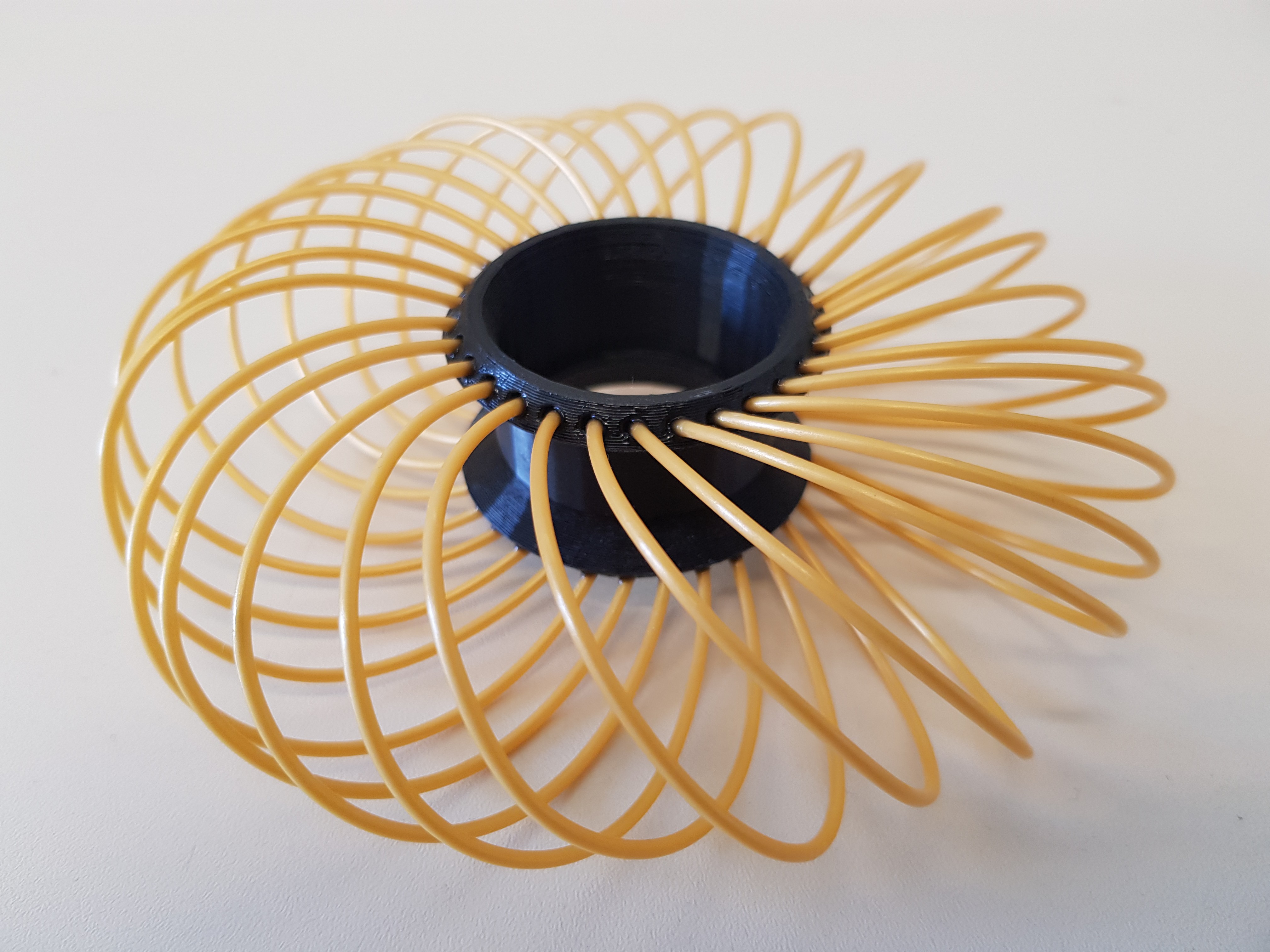
Rather than using rollers for this project, I'm going to try using smooth or ribbed filament strands (such as nylon string trimmer line). The strands should readily slide in one direction, but will grab in the other direction.
This will probably fail on a purely hard surface, but could actually work better than regular Mecanum wheels on soft surfaces.
The strands can flex as well, which will actually make for a pretty decent Mars rover style tire. That was actually the initial thought here, but then I realized the Mecanum potential living within the angled strands.
This should work, but I'll need someone to try it out for me...


 Alex Rich
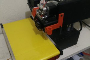
 Chris
Chris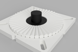
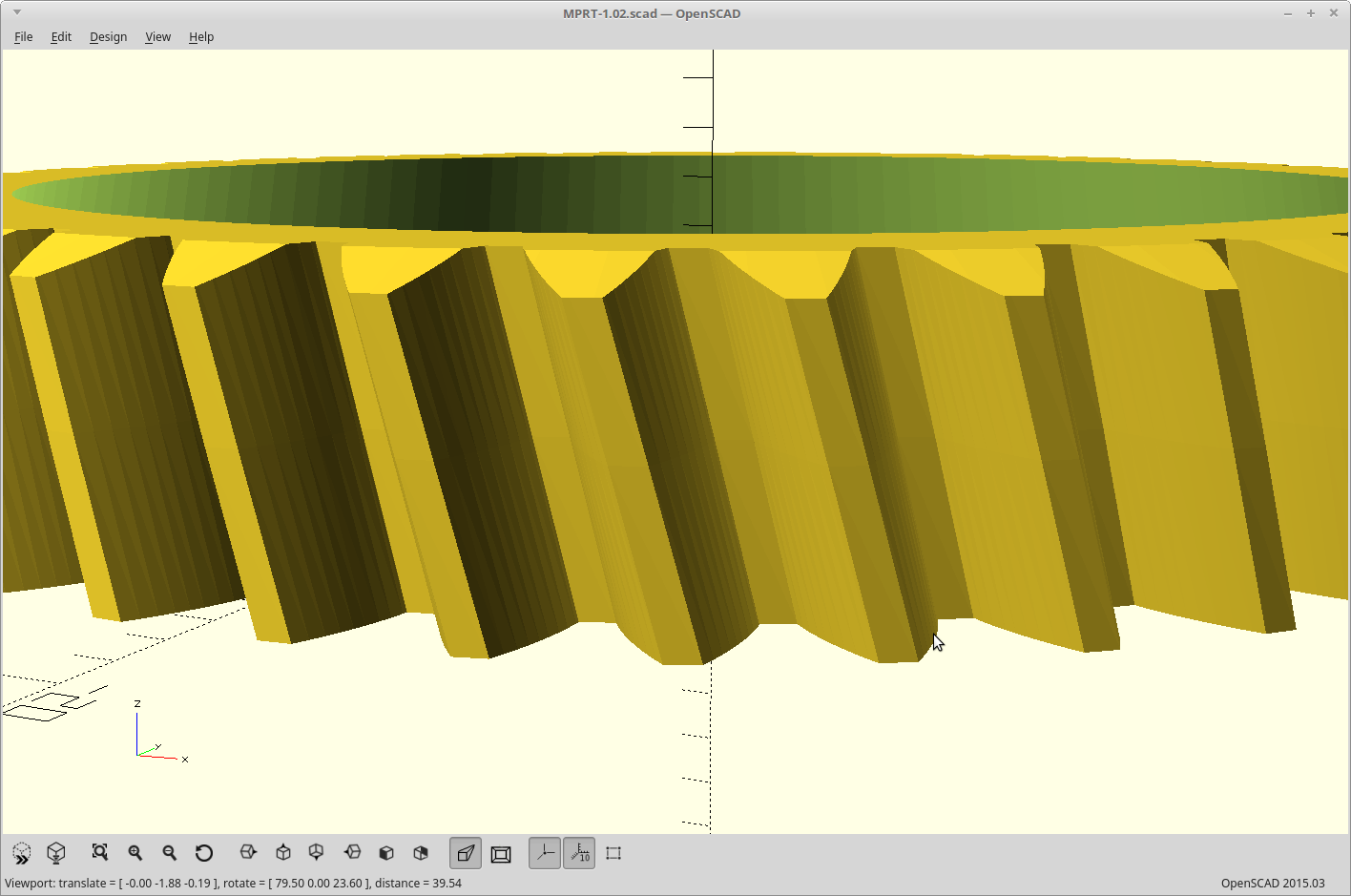
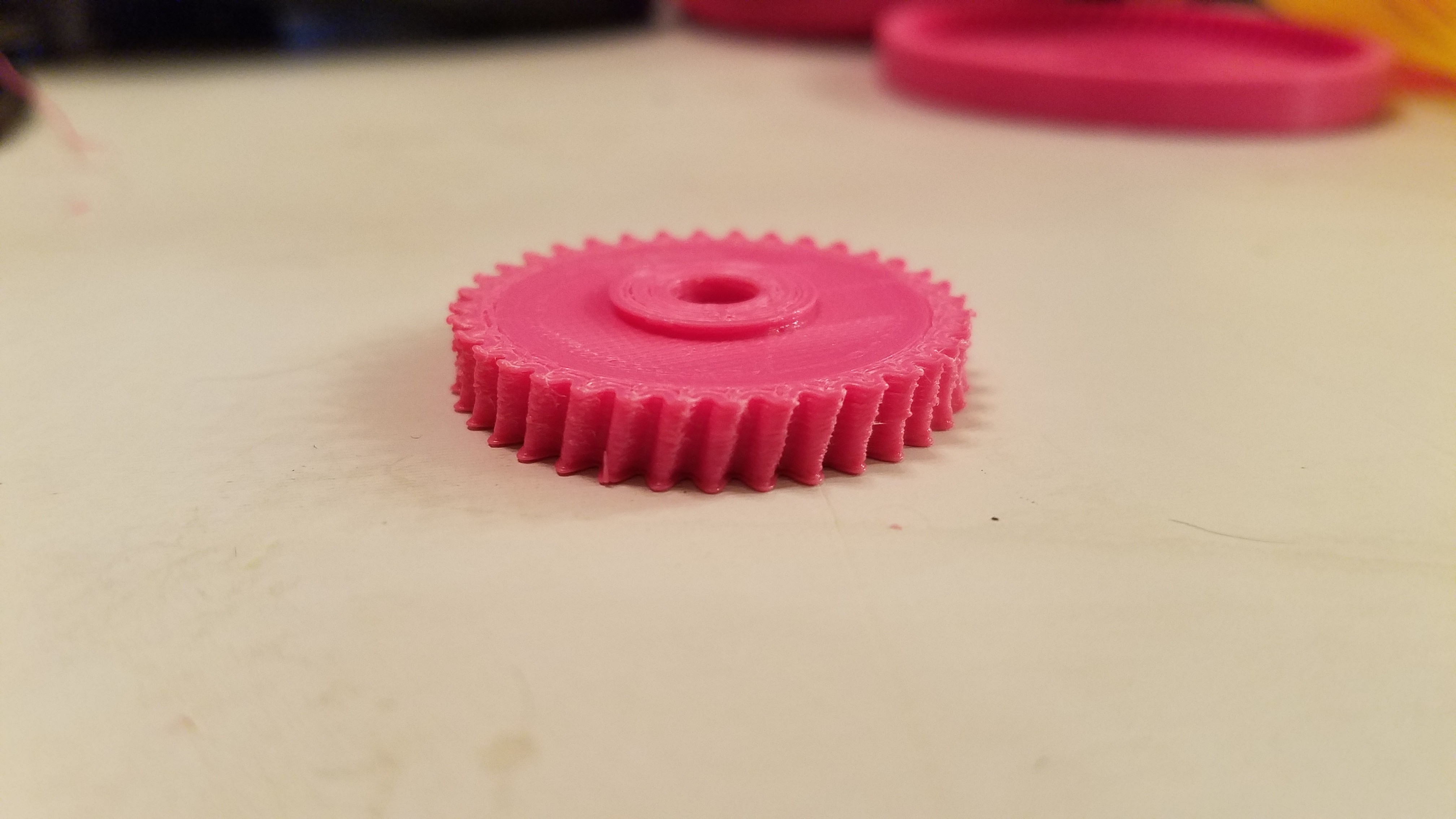
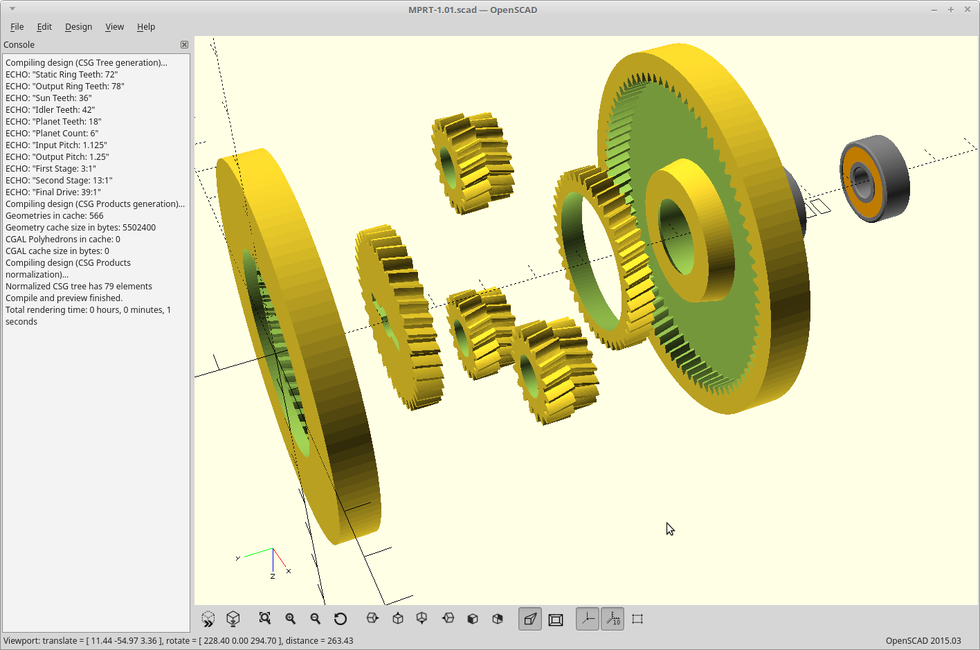
Does this project use conventionally available ring gear geometries? Ex: Does your openscad program design ring gears that are not available from a gear supplier, or are the gears that are produced the sort that can be purchased from a supplier? (I want to know if I can get metal gears).