I have lots of progress on the phone case generator!
The best part is support for flexible filaments. This case better protects the screen and edges while also providing more grip.
Buttons are textured. The area is thin to make the buttons easy to press.
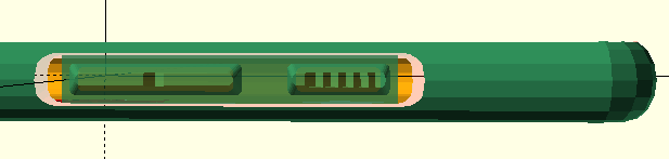
There's a thin section for supporting the overhangs. Remove this with a blade.
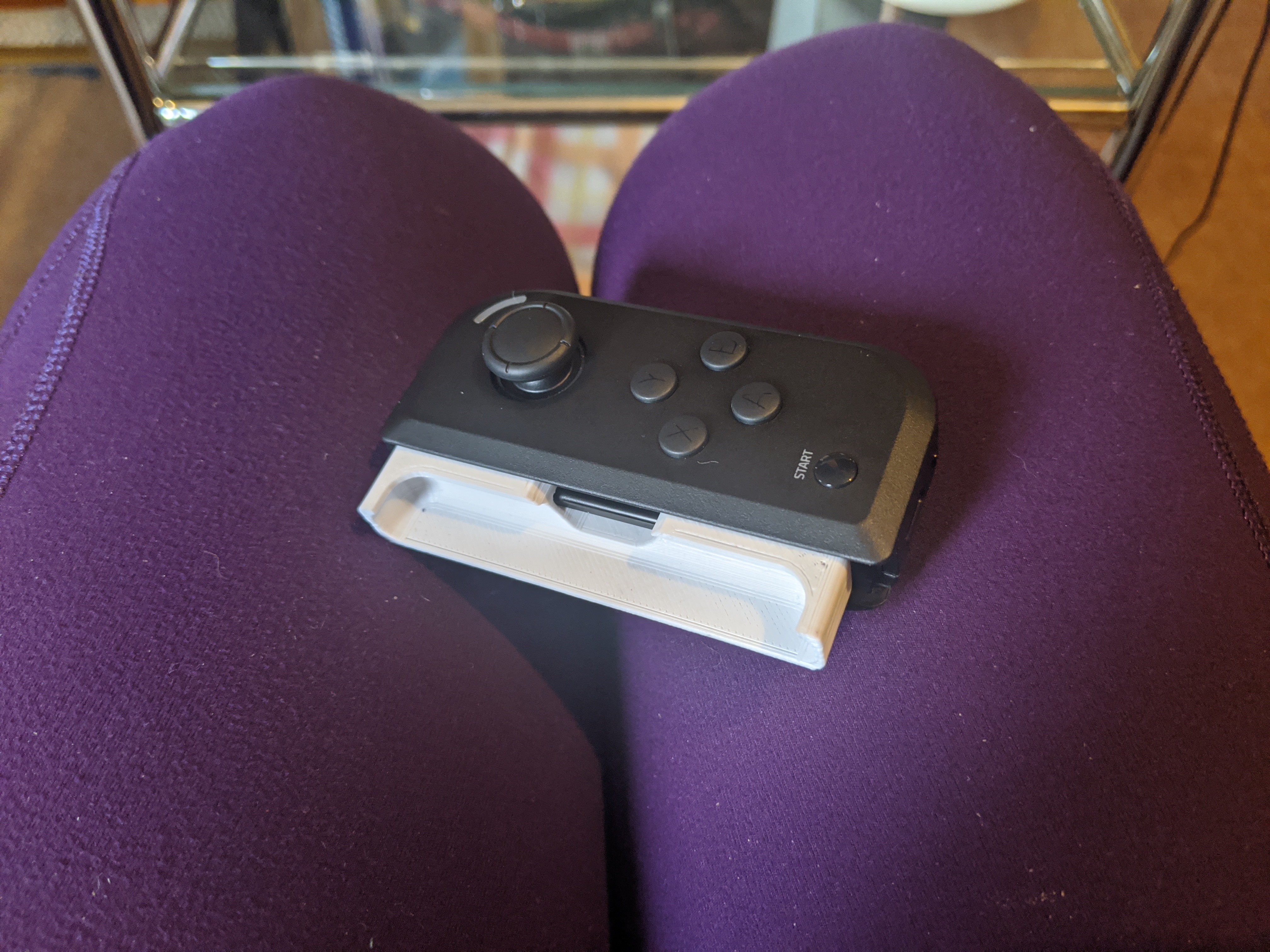
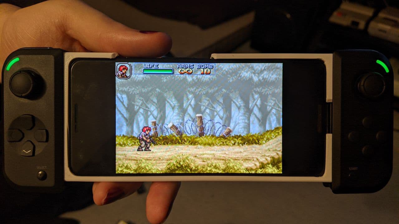
Junglecat rails work decently with TPU. It grips the controller well although the controller can be yanked off. I need to make a hard-plastic cutting guide for the rails
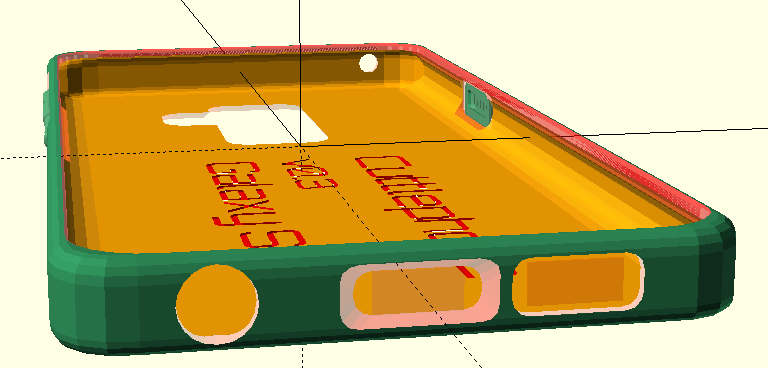
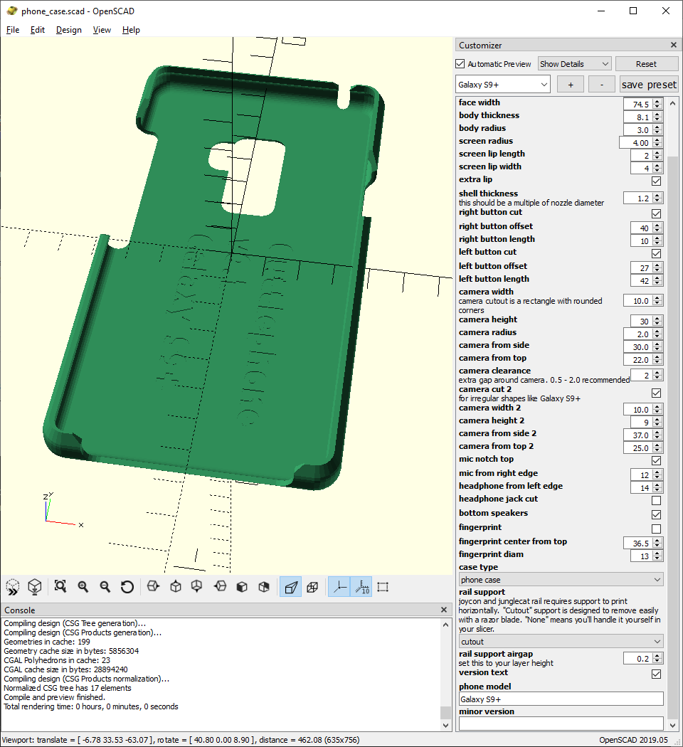
Galaxy S9+ support is here. The inside curves were a pain in the butt and now they're finished. Later I'll tweak the outside edges to improve the feel in hand.
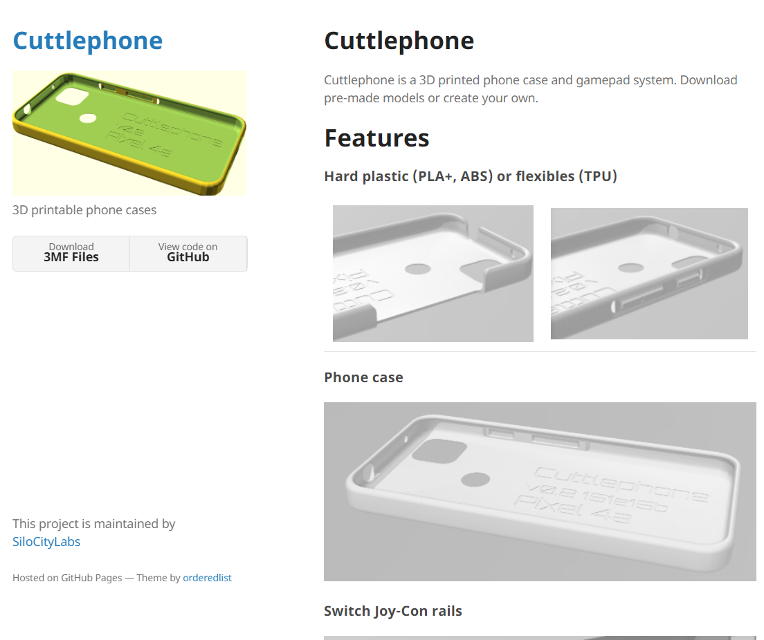
I've made a simple github website for the project. 3D model files are posted here for all the possible case variations. Later I'll write a guide for 3d printing.
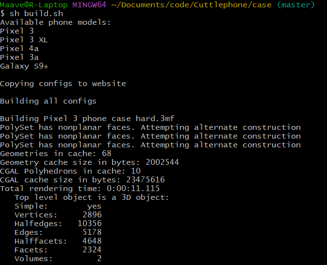
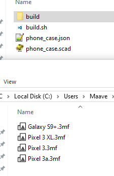
The build script helps here. It generates .3MF files for all configs and copies them to the github site. I want to automatically upload models on Printables and Thingiverse.
Long time no update. Life has been up and down and I haven't focused on this project lately.
Fortunately Junglecat support was kinda easy since I had Joycon rails already. Only took 3 tries. I sliced the model so that the rail tests could print quickly.
Done:
I also changed the version info font to an open-source font. It's much easier to read.
I may remove Joycon support. They're big, make the phone case absurdly thick, turn on by accident, and have poor emulator support. Junglecats have a slimmer rail that makes a much better daily driver phone case and they work as a single device in RetroArch.
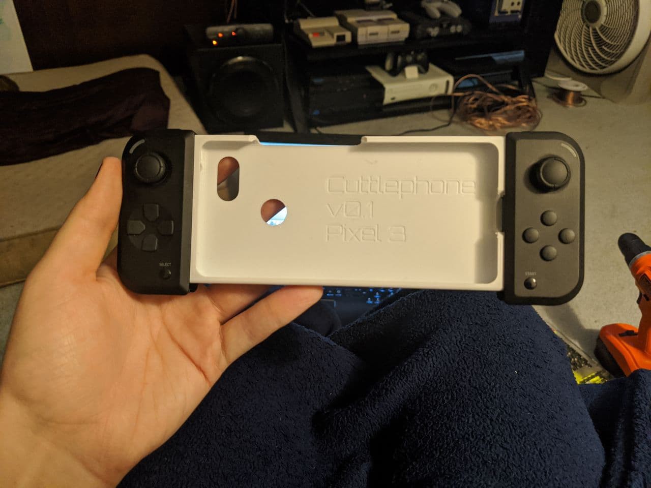
I've officially named the project Cuttlephone, after the shapeshifting Cuttlefish.
I've been putting decent work into the OpenSCAD case lately. A friend and I both use it as our regular phone cases. I have Pixel 3, he has a Pixel 3a.
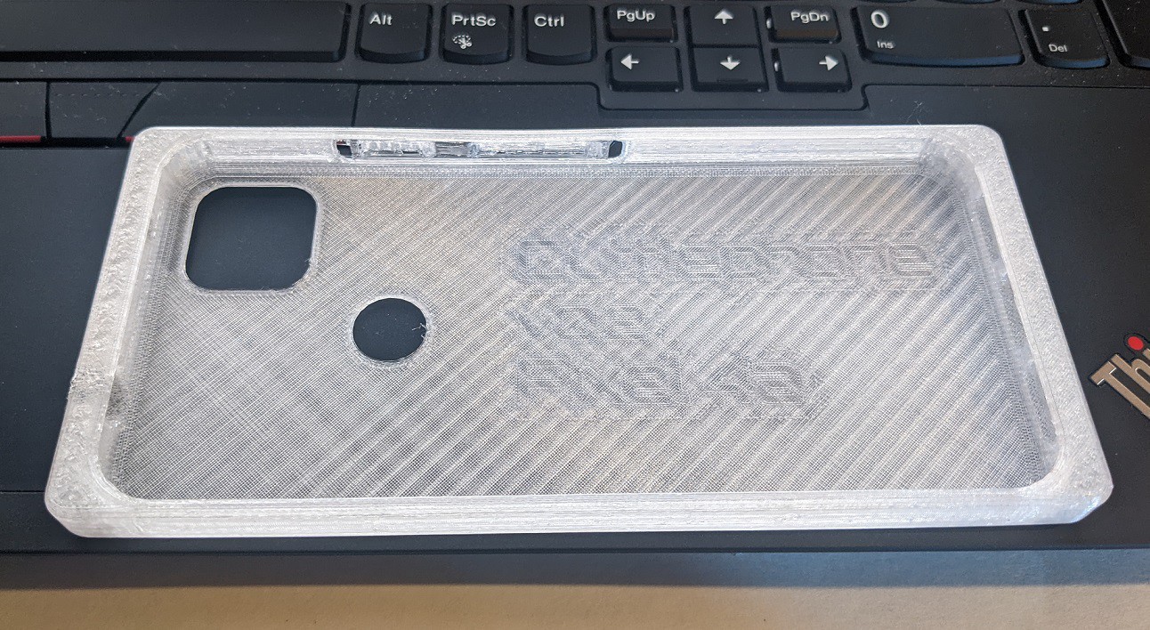
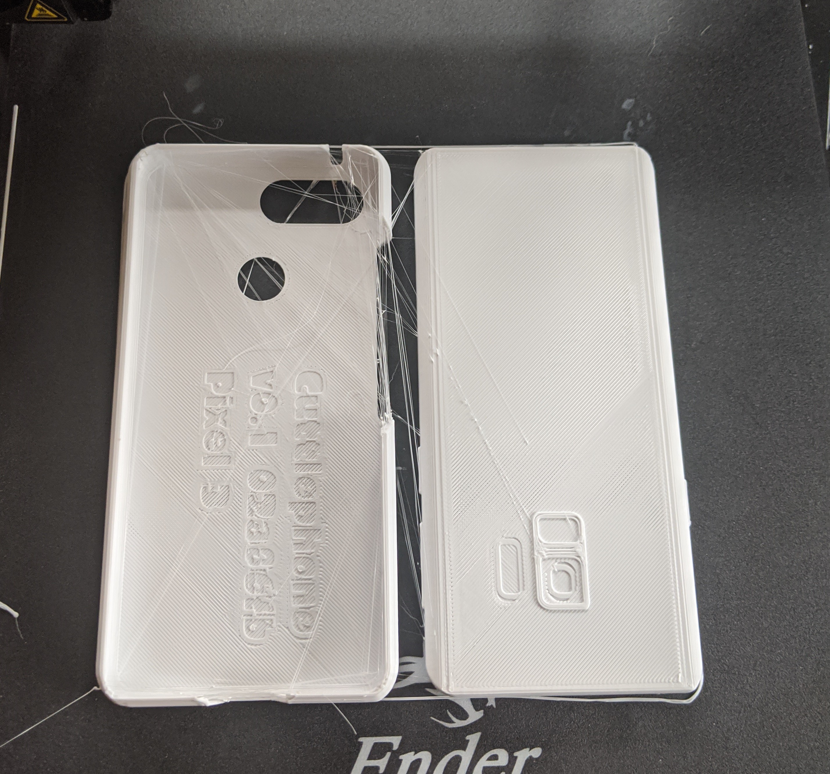
Here's an early version of my case and a mockup Galaxy S9 used for testing. Text is embossed including phone model, case version, and git commit hash (sometimes debug cases don't have git commit). I've been printing in white because it's easier to see details. I love the Splatoon font - unfortunately it can't be used for commercial purposes so it will eventually go away.
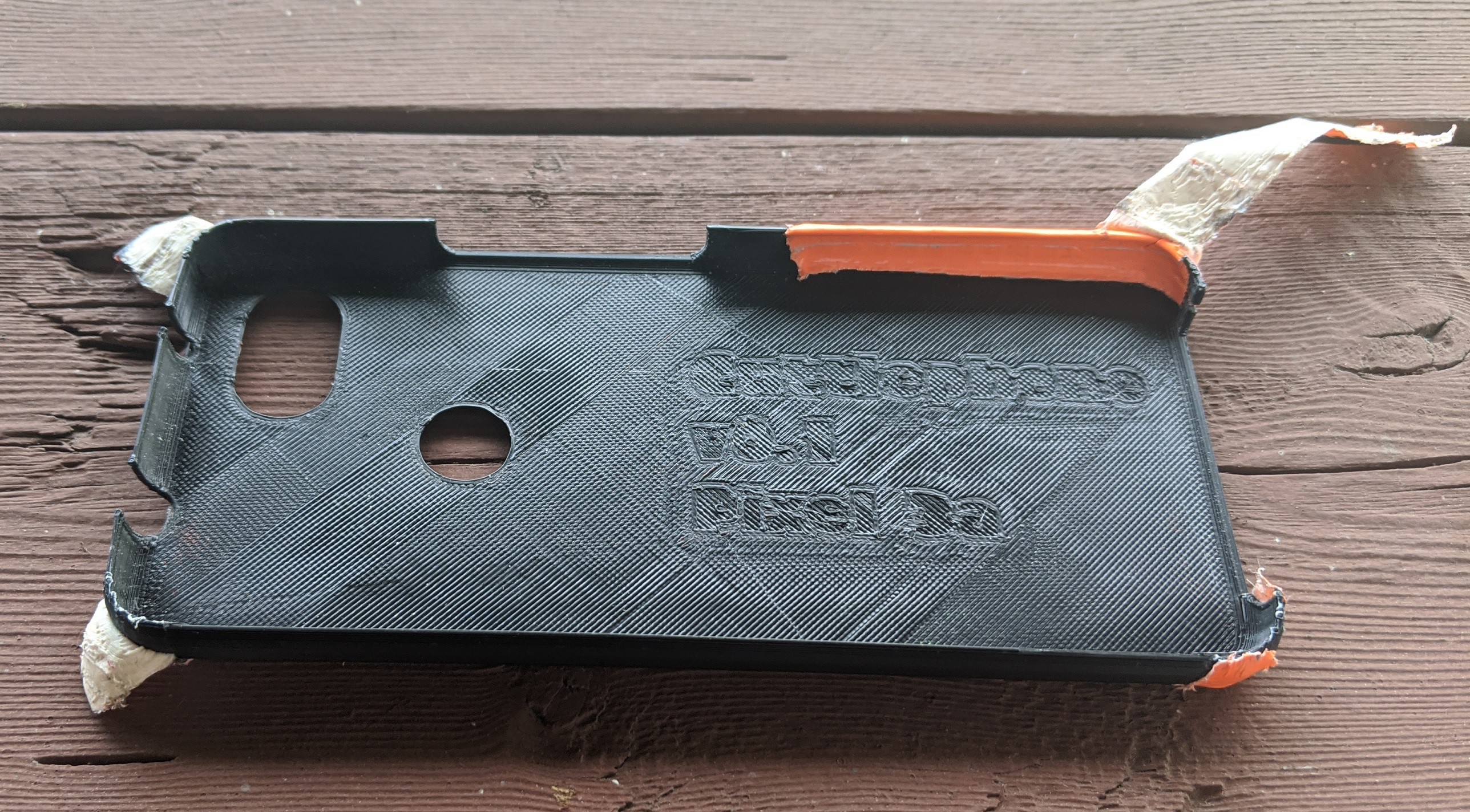
Here's my friend's case after a month of beating on it. He used duct tape to patch the corner and improve for visibility. We'll be trying different colors later.
A number of details were improved such as thickness, lip to protect the screen, phone insertion/removal, reduced snagging on clothing, more finger space near buttons, etc.
It looks similar but performs much better.
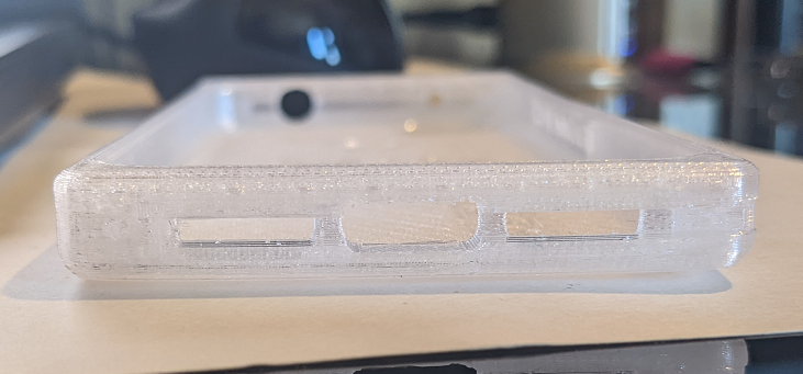
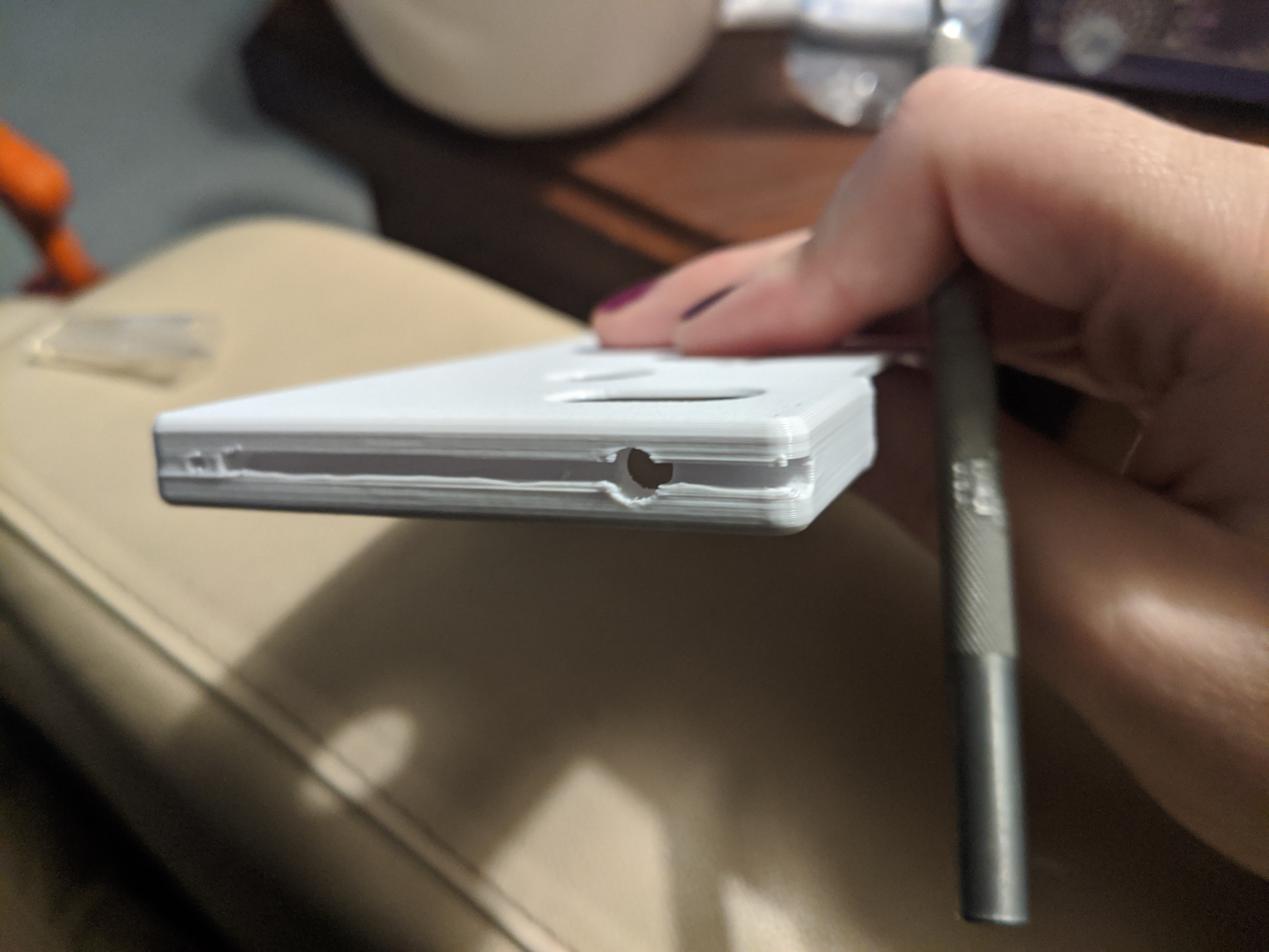
You can see the anti-snag bevel here. Fillets in OpenSCAD are difficult so this is a simple 45-degree cut. Filing is recommended. This pic also shows a known flaw - thin corners that eventually chip. This geometry needs to be improved.
I also have a working build script. It will generate 3d models (3mf or STL) for all the configs available. I'll be using this later to release pre-rendered models for all phone models and all case types.
Galaxy S9+ case is in the works and will be tested and tweaked by ldrrp. My end goal is that somebody could take their phone, measure it with calipers, make a config, and have a functioning case in 1 or 2 prints. Phone support would be driven by the community.
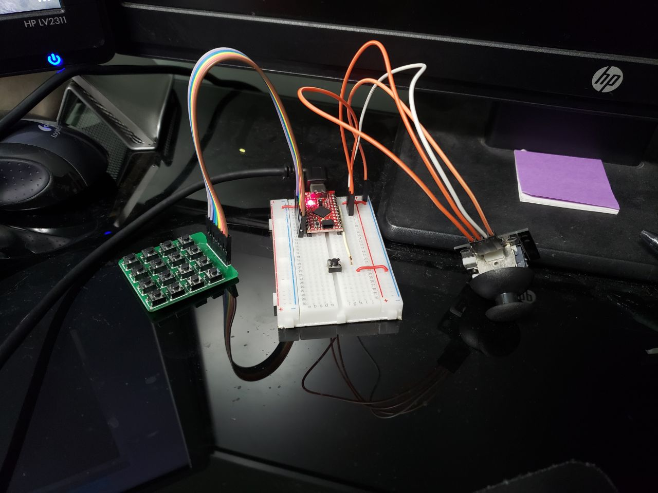
Added i2c pcf8574 to the mix. I did not want to run 12 connectors over but i also wanted to keep the software simple so we added one for each side. Unfortunatelty i cant find an affordable ic with both analog and digital multiplexer so the joycon still has to be run accross. 6 total accross the phone still beats the old design running 8.
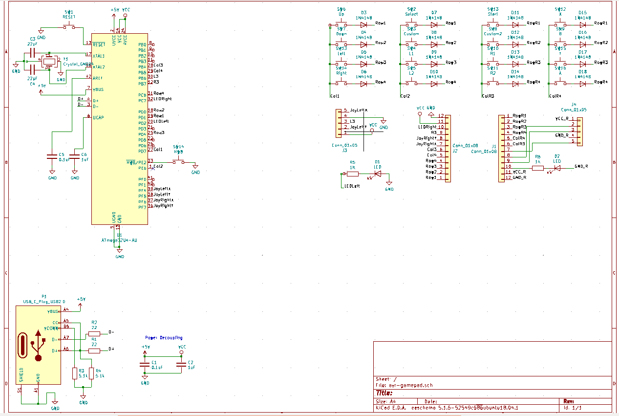
Each multiplexer will have 3*3 matrix buttons, L3/R3 and and led indicator for a total of 8 pins.
[maave] is adding my s9+ to the case designs while help out with the schematics.
Added firmware to repository to start testing new breadboard version.
Switched schematic to use a matrix button layout, also cleaned things up a bit. Added diodes to prevent ghosting. Unfortunately had to add more pins to connector going across. I think i might just use i2c over to the other side for only 4 pins over to each side. I just wanted to avoid adding more complexity.
We're pulling the plug on our old 3d printer, the CEL Robox. It has died too many times. We're not repairing it again. [ldrrp] got an Ender 3 and I got an Ender 3 Pro (nearly the same but with a magnetic bed). Both are awesome and we've been cranking out prints.
I've been working on the case a lot recently. No more Fusion 360. OpenSCAD is proving to be much more flexible. It's also rather easy for me to understand as a programmer. User customization and conditionals will make this shell truly configurable for multiple phones. In the future expect to see automated STL builds using config files for more phone support.
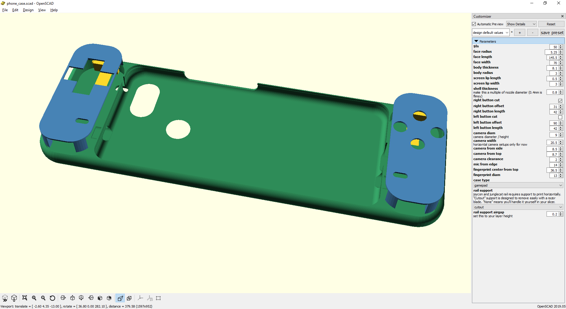
Gamepad progress:
- body complete - gamepad faceplates are mostly implemented. Button size/location subject to change - triggers need a lot of work - Joy-Con rails work - Junglecat rails are placeholders
Old gamepad PCB sitting in the last print the CEL Robox was able to achieve. This version had several overhang issues in the 3d model that I've fixed. Phone fit was also whack.
Peep these customizer options. I can use conditionals to add or remove large chunks of the case. Phone case simply has no gamepad features.
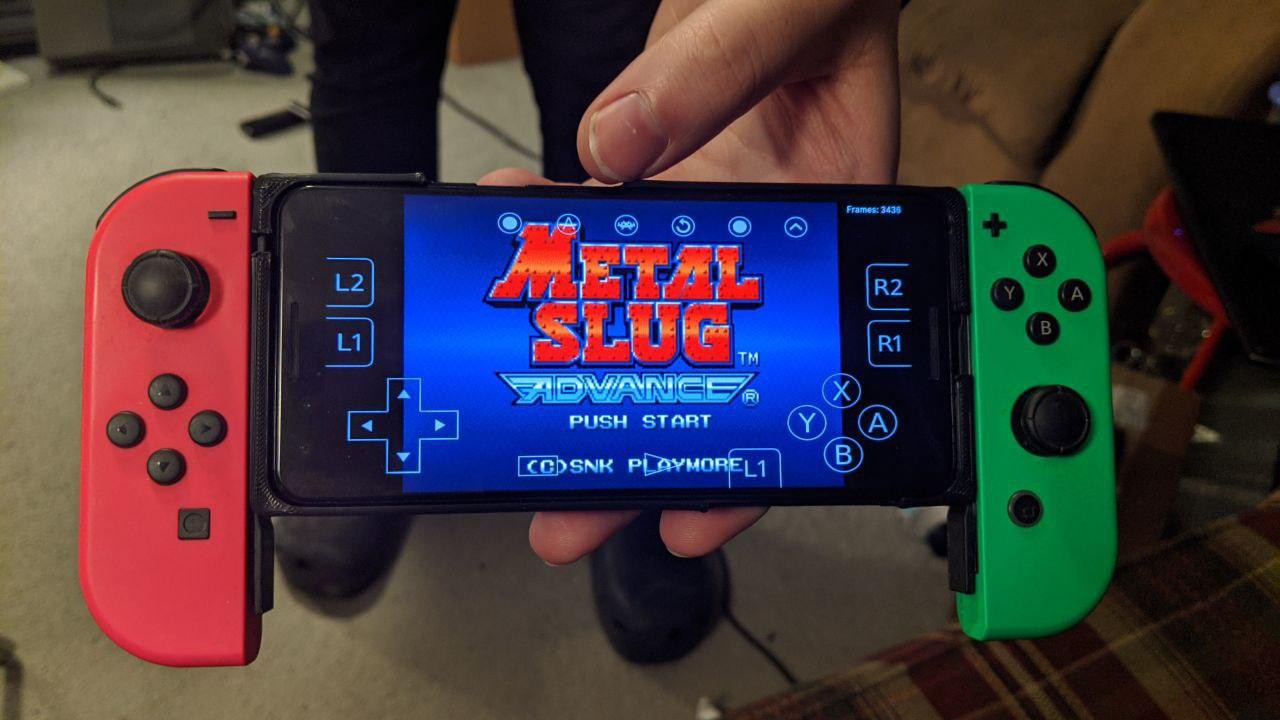
Joy-Cons are ready and Junglecat support should be easy when I have dimensions. This will be cool when more phone configs are added. The Razer Junglecat only has cases for 4 (four!) phones right now. Maybe I can convince Razer to send me a Razer Junglecat. I'm not spending $100 on those right now. If anybody has a set and some calipers, contact me.
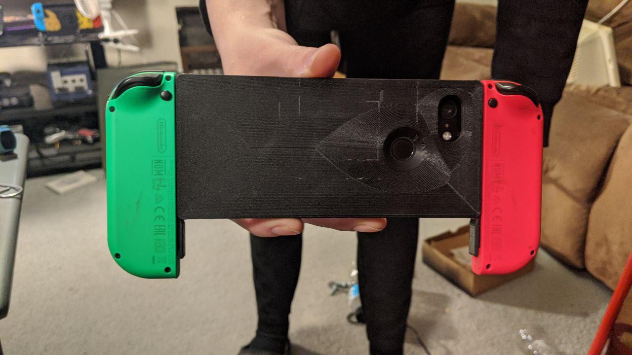
Here's the side of the Joy-Con version so you can see the railsThe case works. Unfortunately many emulators (RetroArch, PPSSPP) don't support input from 2 devices at once. Dolphin emulator handles it though. On top of that, my phone gets the infamous Joy-Con lag which makes these unusable until I can find a patch.
Check out this ugly bottom infill pattern. I've since changed the slicer settings.
v0.2 PCB will be delayed a bit. I've decided that I need analog support ASAP. I see a lot of comments on other devices, such as the Game Kiddy 350H, decrying the lack of dual analog which is needed for some PS1 titles. Since phone emulators are starting to enter the PS2/Gamecube era I definitely need this support. I'll try to support 1 full joystick with L3/R3 (probably Switch joysticks) and 1 slider (either PSP3000 or 3DS) so the builders can pick high profile or low profile analog.
I received my PCBs and components. I tried to assemble. I failed. The flex PCB and QFN parts were more challenging than I expected and I botched soldering the atmega and FFC connector. Rather than sink more time into an early design, I've decided to cut my losses and continue to v0.2. I could complete v0.1 with the help of a friend however v0.2 has so many changes and v0.1 has several flaws (not dealbreakers but annoyances) that I think my time is better spent moving on.
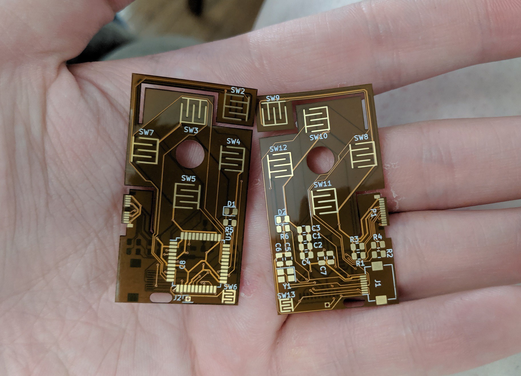
Fresh PCBs
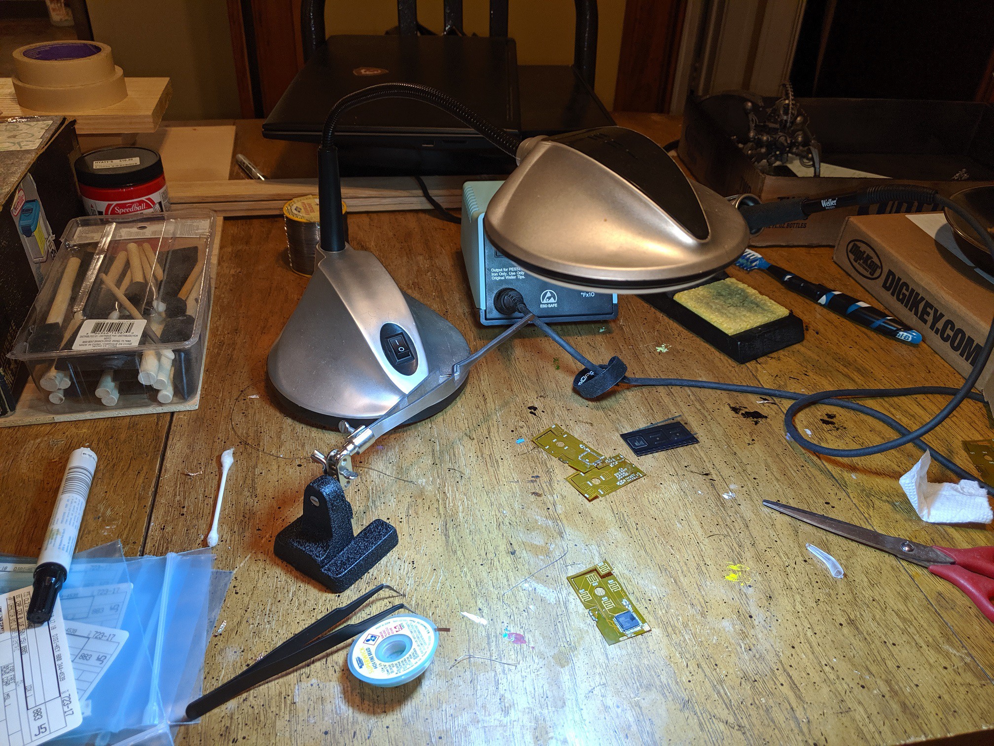
The craft table. This LED light is the best thing ever. Light is so important for seeing small details. The next upgrade will include magnification.
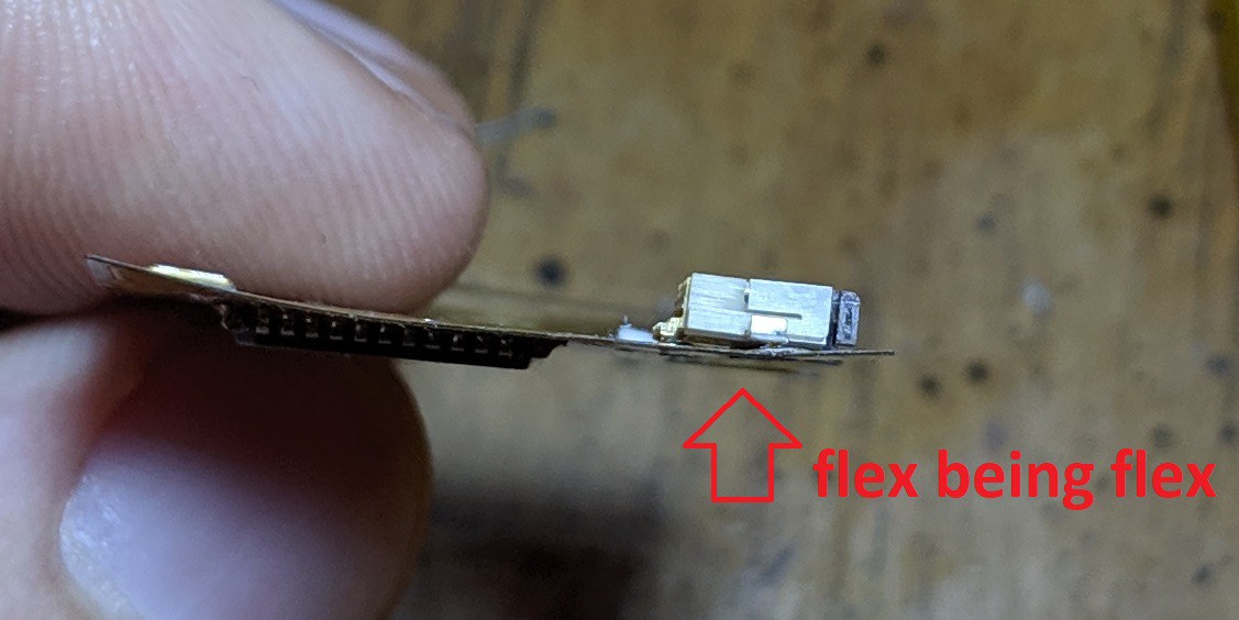
An example of flex being a pain in my butt. The board is flexed and creates too much gap to solder properly.
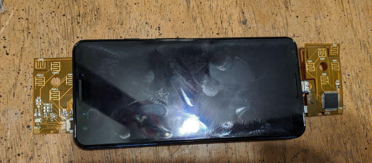
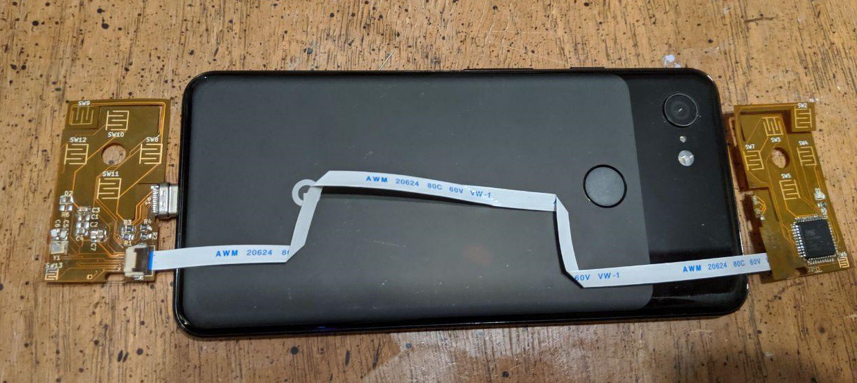
Here are 2 boards connected and mocked up on a phone.
The FFC is very flexible. It can handle one-time bends too. This gives me more options.
Lessons from v0.1:
- review instructions before attempting new soldering techniques
- use the right tip (mine was too fine and I couldn't find the spare)
- tape down flex boards
- the flex trigger works well
- you can't hold flex PCB in alligator clips. It bends the PCB which misaligns pins/pads. Taping it to a hard surface works.
- attaching the USB-C connector (meant for 0.8mm FR4) to the thin flex was a bad idea (I knew this but wanted to try anyway)
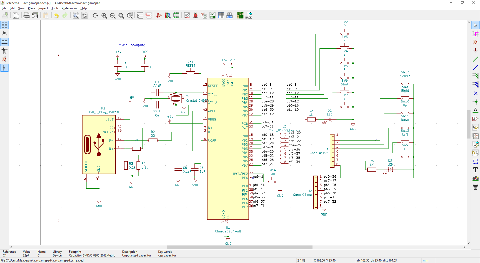
- read the datasheets, I wired a 4-pin crystal wrong (could be kludged)
- the USB-C connector sticks out more than expected
- the FFC cables are very flexible and easy for a user to install
- reusing the same board for both sides of the phone complicates the routing
- reusing the same board increases the board size, negating some of the benefit
- the yellow flex PCB is kinda ugly and would limit art
- components on both sides are annoying to solder (I knew this but wanted to try anyway)
- why didn't I put debug pads on this?
- my "space saving" reset button is difficult to use in practice
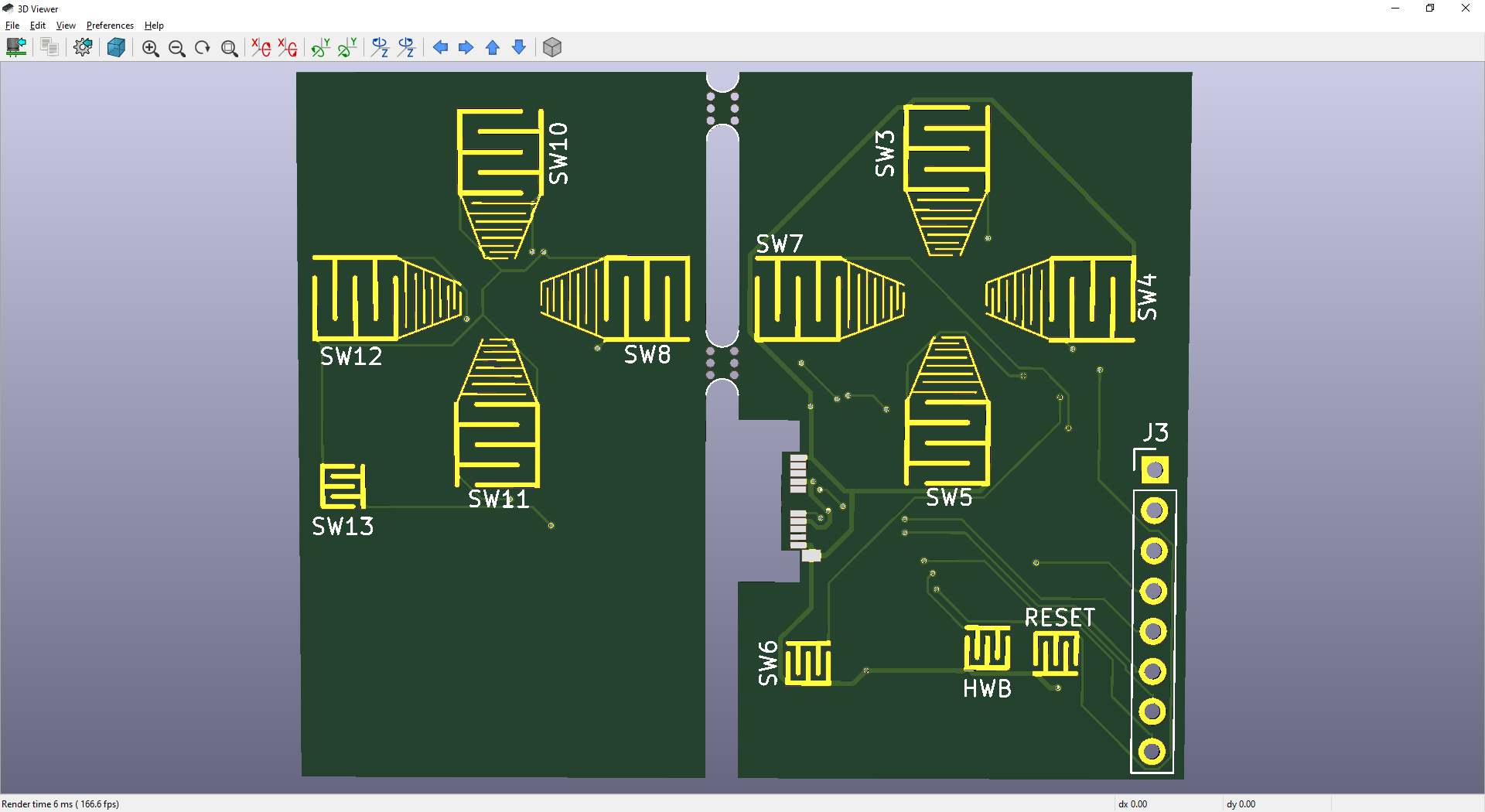
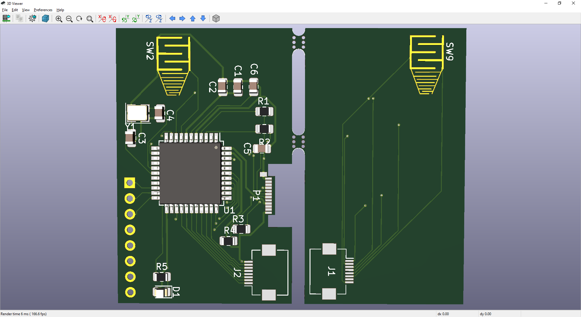
Let's take a look at v0.2 (not final).
Changes for v0.2
- flex features have been removed
- moved all components to one side
- the trigger will hinge, similar to the Switch trigger. This simplifies the PCB but complicates the case
- the double sided feature (reusing the same board for both sides) is gone
- a few 0.1" standard headers are added, connected to some digital and some analog pins
- USB-C connector has been recessed so the PCB sits closer to the phone
- the face pads have be reshaped to accommodate silicone buttons from multiple controllers
- plans to use Switch Lite silicone and buttons as soon as they're available aftermarket
- added simple PCB art
- crystal wiring has been fixed
- FFC location has been fixed so I can use straight-through FFC
My roommate got a Switch Lite and the buttons are excellent. They're firmer than the DS or PSP face buttons, the buttons sit a little higher, and I can feel the rubber dome collapsing (unlike the PSP face buttons which are mushy, there's not much tactile response). These are the best handheld console buttons I've felt yet and they'll work perfectly in the controller once more aftermarket parts are available.
The headers are intended for debugging, programming, and testing future features like analog joysticks and audio output. However I realized that they could be an attractive feature. This is the first atmega32u4 breakout I've seen with a male USB-C connector (the Elite-C and Goldfish have female USB-C). This could open the door to other DIY phone accessories.
v0.2 is almost ready and the PCB will be ordered soon. I've recruited the help of my friend [ldrrp] to ensure 0.2 works the first time.
This is taking longer than expected unfortunately. I got my Digikey parts in like 2 days though. I'll see what I can work on in the meantime (firmware or other projects)
Thank you Hackaday and Digikey for the flex PCB coupon!
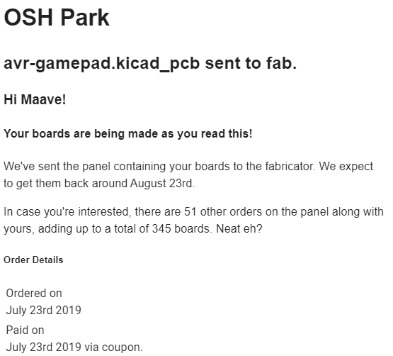
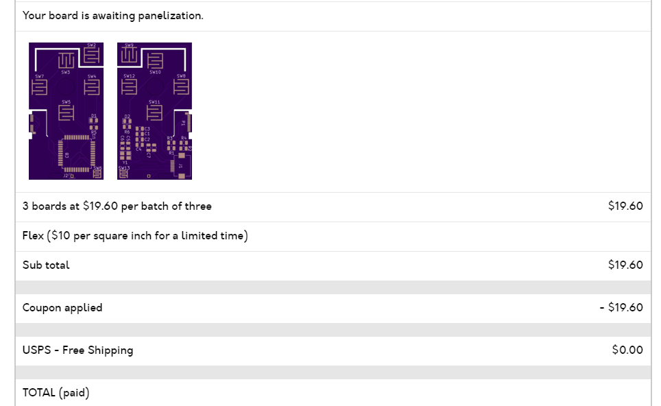
OSHPark takes .kicad_pcb files directly so ordering this was stupidly easy. August 5th product date. Mark your calendars! Most of the components were ordered from Digikey except for the USB-C connector (Molex 105444) which was out of stock. Had to order that from Mouser. For all the Digikey parts I picked the parts following this video, picking SMD components, and I uploaded the BOM CSV for easier ordering.
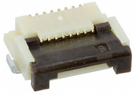
I swapped the solderable headers with a FFC connector. This is a small flat cable that's common, generic, and cheap. I settled on the FH12-8S-0.5SH(55) which is a 0.5mm pitch 8-pin cable. This connector had a small enough footprint that I could fit it in the existing 2sq inch outline.
-Power and ground tracks have been made thicker. I set this in the net classes which the autorouter uses.
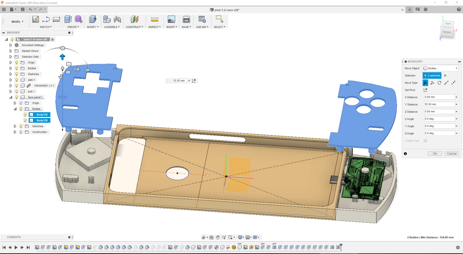
-Retention pegs and cutouts have been added to keep the PCB in place.
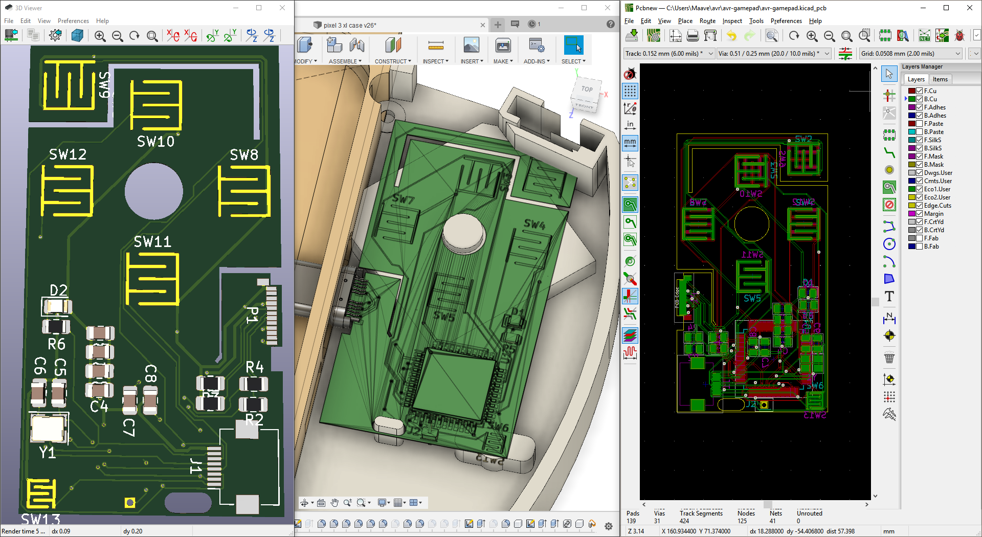
-Modeled top panels.
One more review then 'll order the PCB and parts. I have lots of ideas for the future but I want a working unit in my hands first.
 Maave
Maave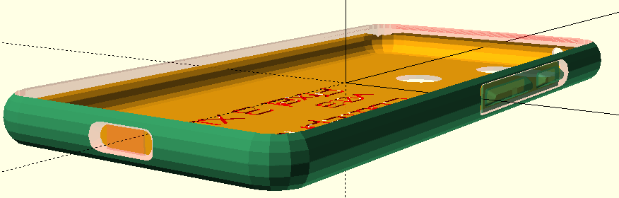

 Here's my friend's case after a month of beating on it. He used duct tape to patch the corner and improve for visibility. We'll be trying different colors later.
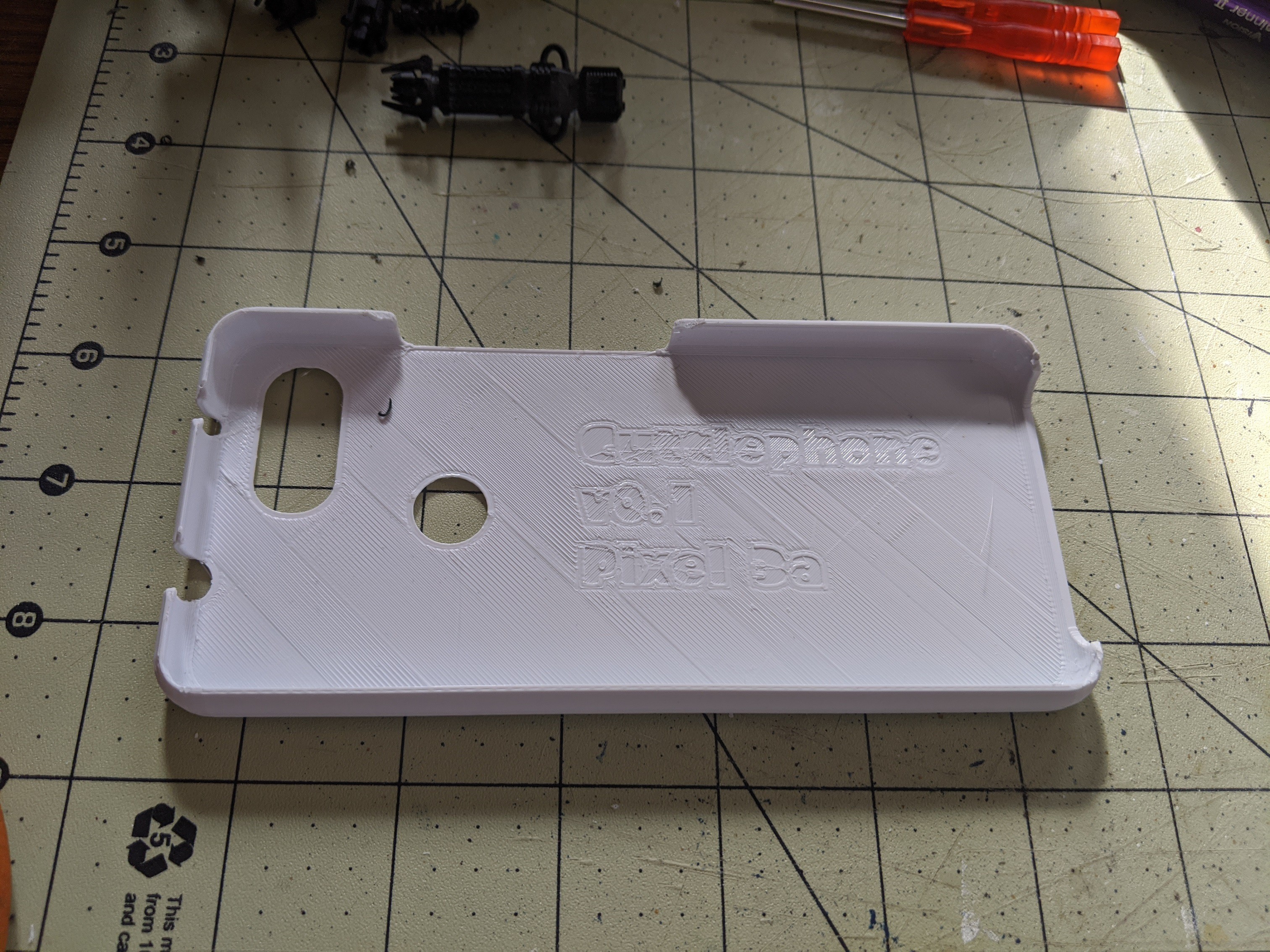 It looks similar but performs much better.
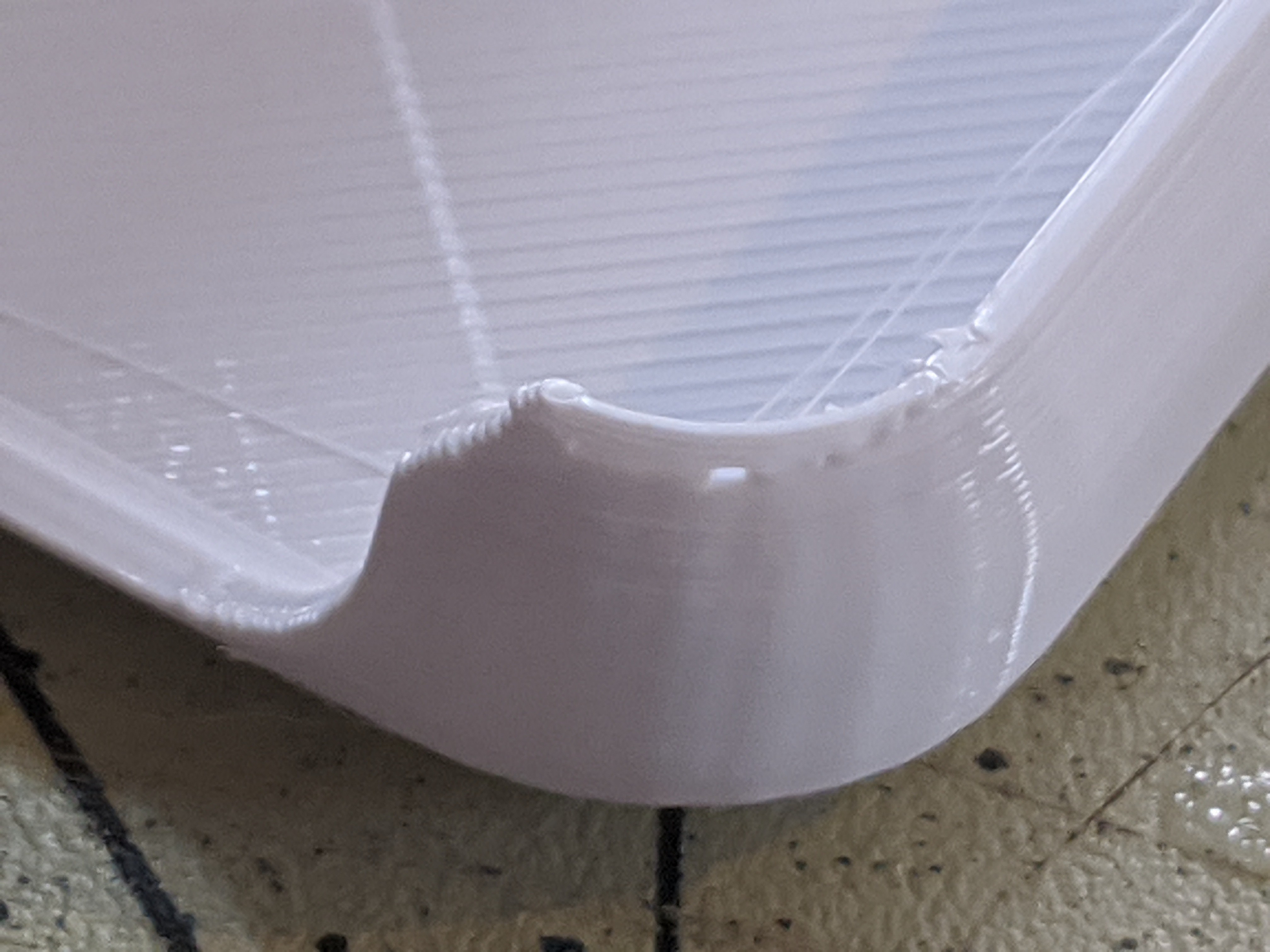
 Old gamepad PCB sitting in the last print the CEL Robox was able to achieve. This version had several overhang issues in the 3d model that I've fixed. Phone fit was also whack.
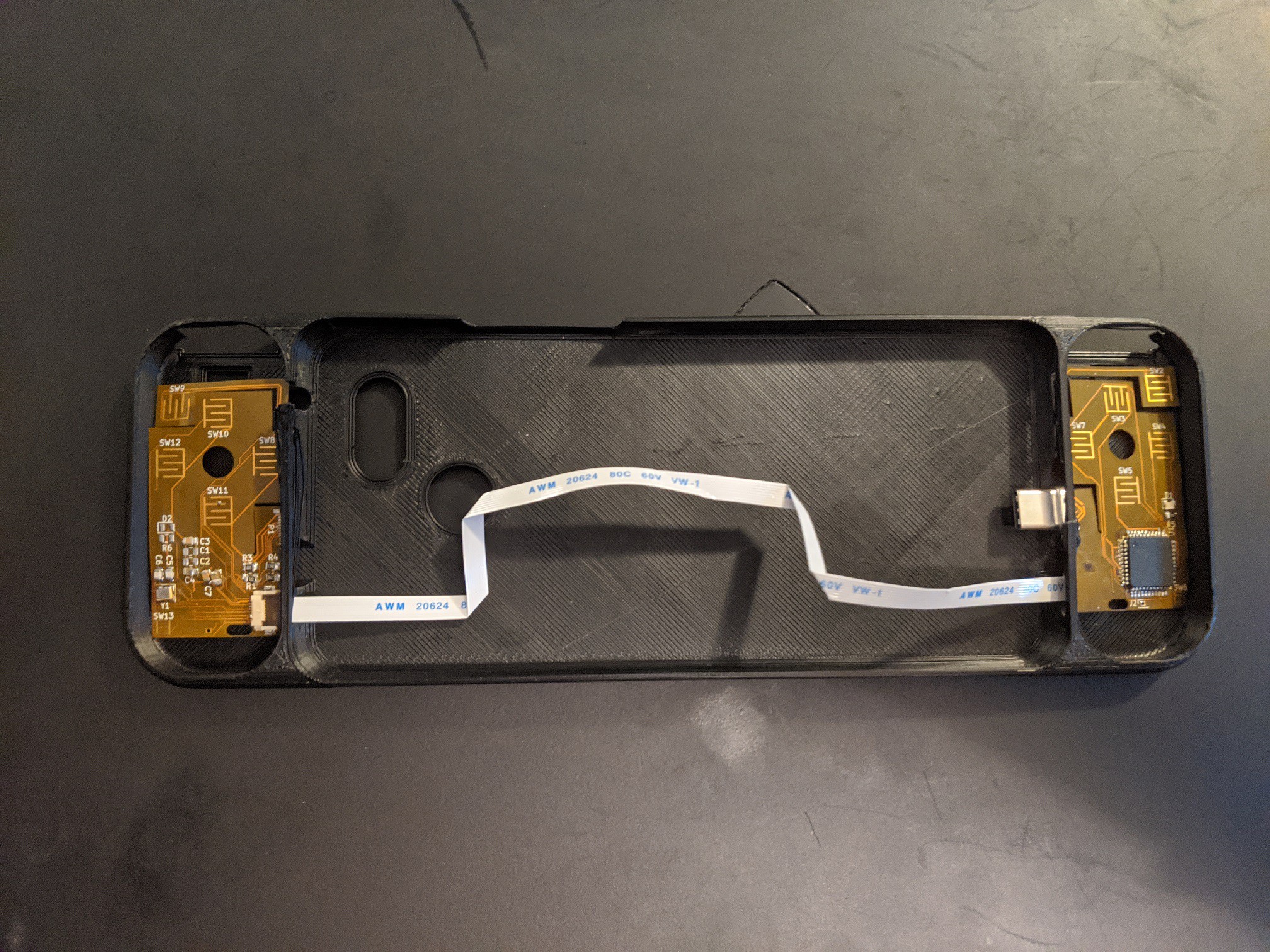
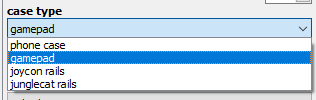 Phone case simply has no gamepad features.
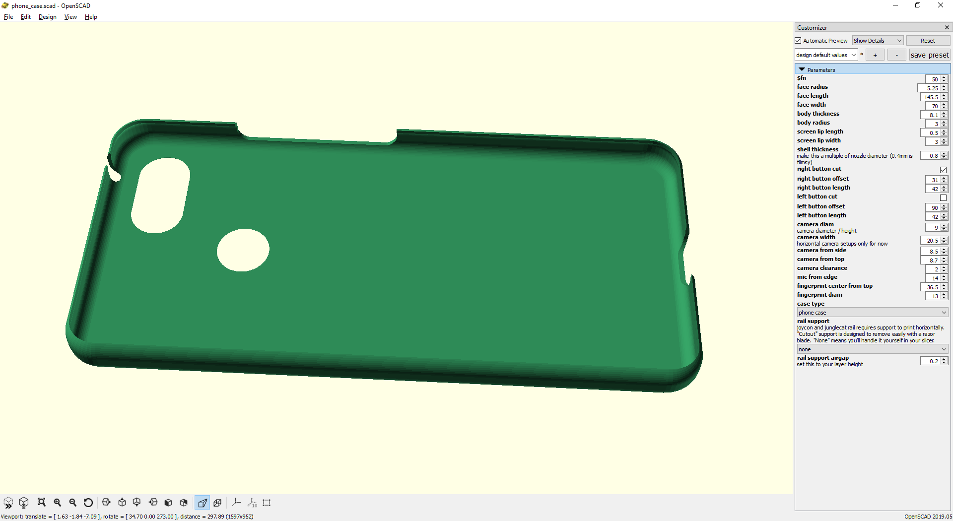
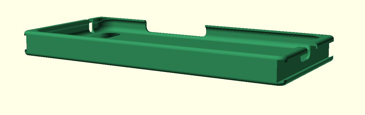 The case works. Unfortunately many emulators (RetroArch, PPSSPP) don't support input from 2 devices at once. Dolphin emulator handles it though. On top of that, my phone gets the infamous Joy-Con lag which makes these unusable until I can find a patch.