Maave
Maave-
Phone case half done, PCB nearing final
06/25/2019 at 03:25 • 0 commentsThis was a slog. Lots of measuring with calipers and fiddling with Fusion. I did a lot of work that I had to refactor it into another body, got a couple graphical glitches in Fusion, struggled to import the PCB for reference, etc. But it's a little over half done now.
v1 case todo:
-cut a slot for the wires that connect each half
-make a top panel to hold the buttons in place.
-shape the start/select button slot
-hold the PCB into the case?
I've based this off my Nexus 6P case. The measurements haven't been adjusted for my Pixel 3 (not XL) yet. I'm going to leave it as-is for easy removal and so I can fudge the location of the phone. v1 is being designed with front access for easier debugging.
![]()
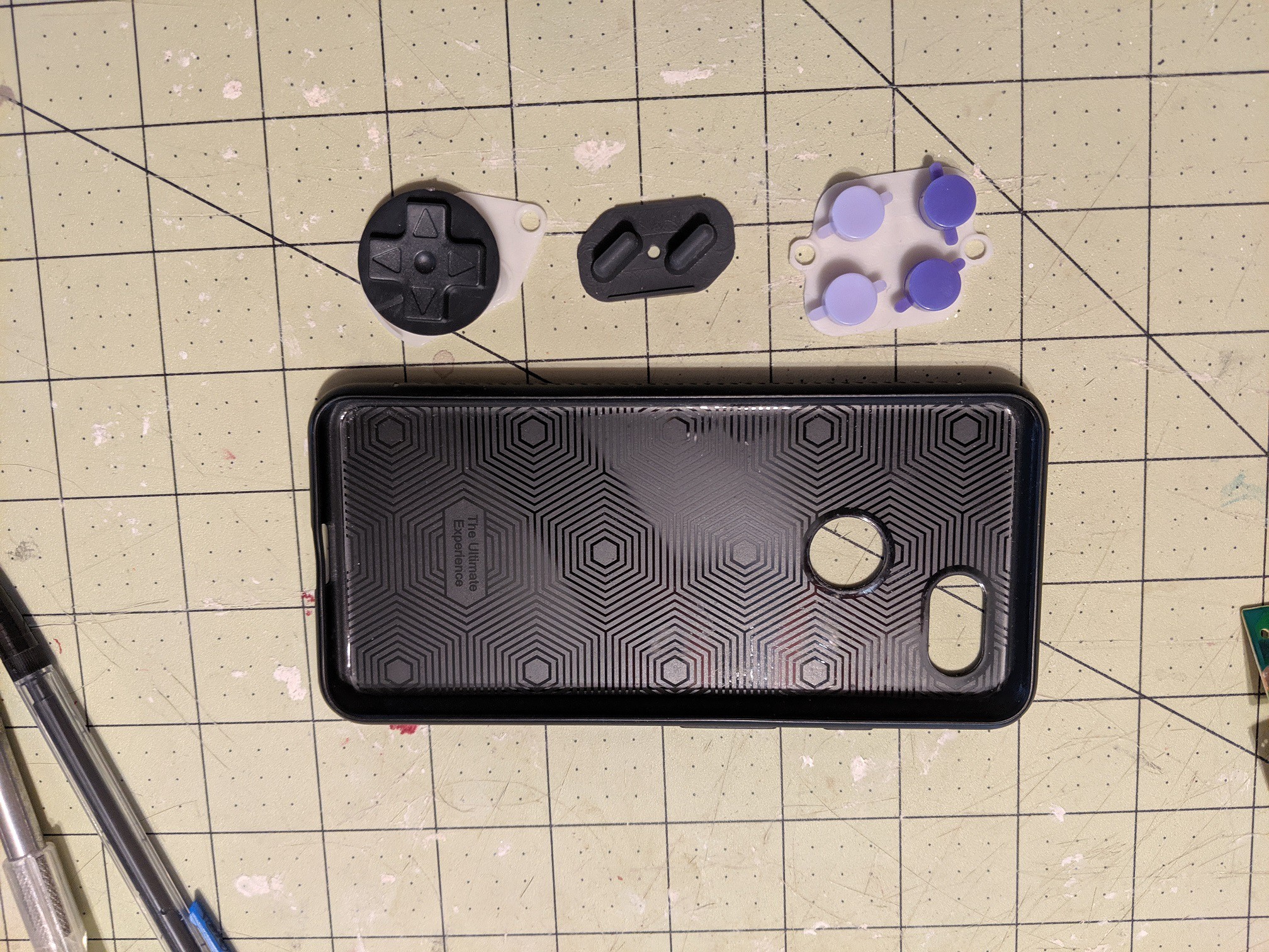
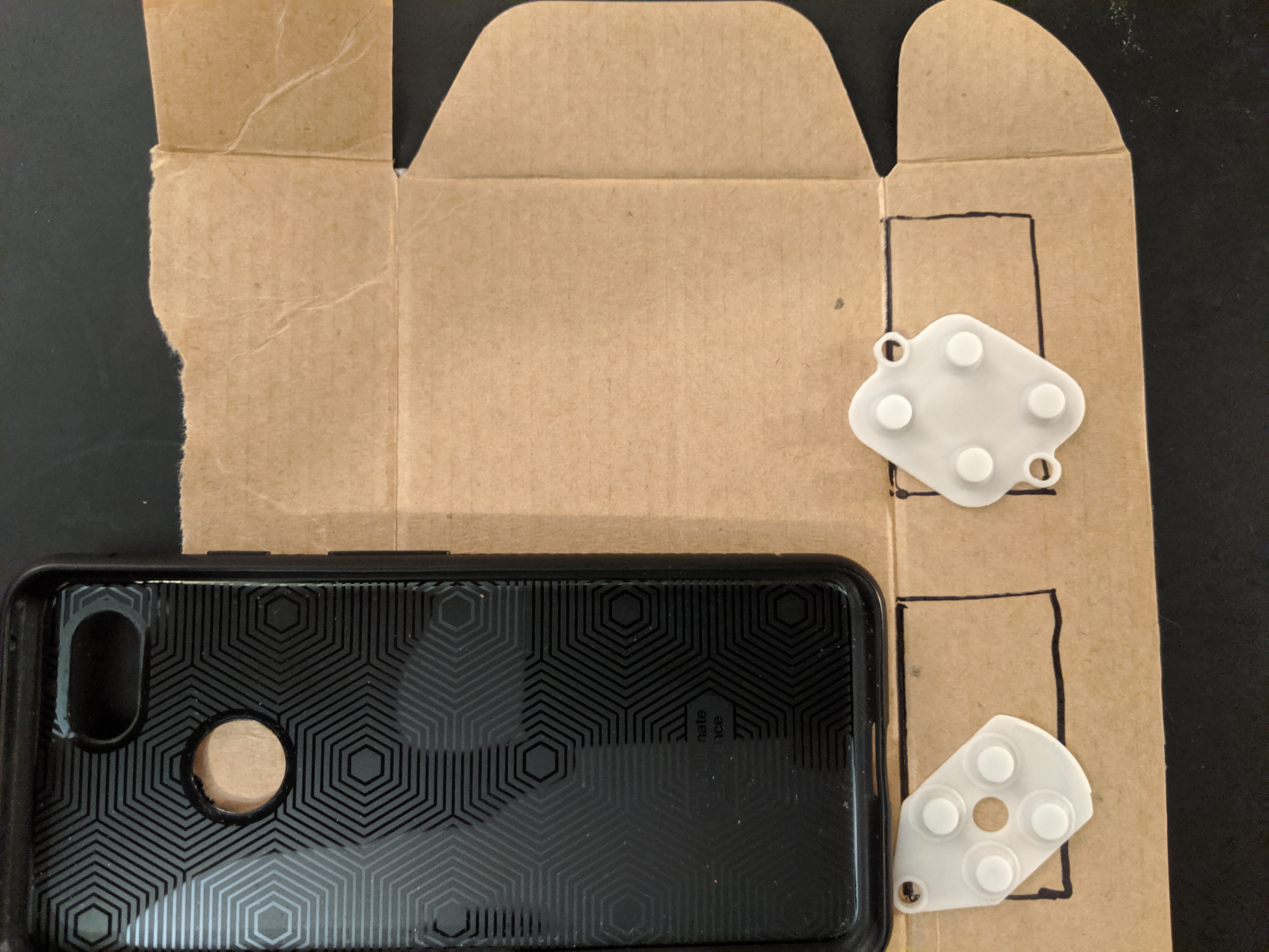
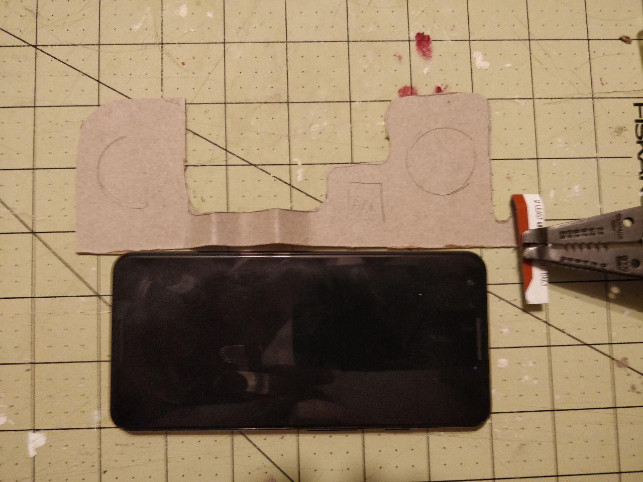
Here's the inside of the knockoff SNES controller that I based this on and took measurements from. v1 will use the D-pad and face buttons, two of the D-pad rubber (I have another) because they're narrower, the start/select rubber cut in half, and the shoulder buttons and rubber.
![]()
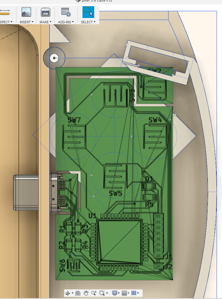
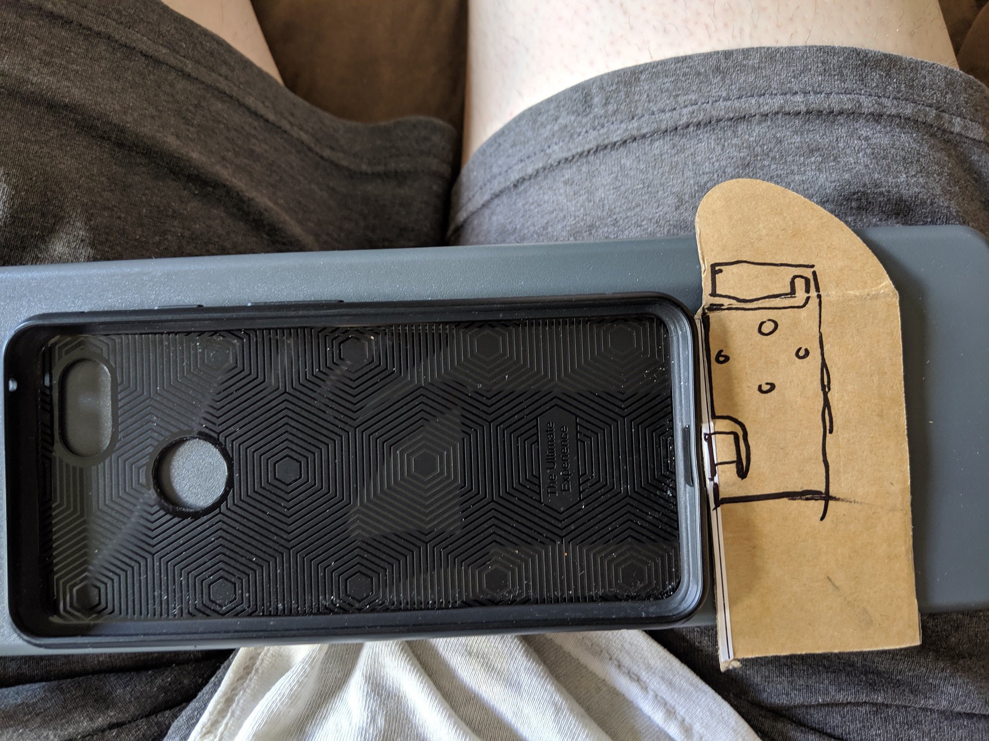
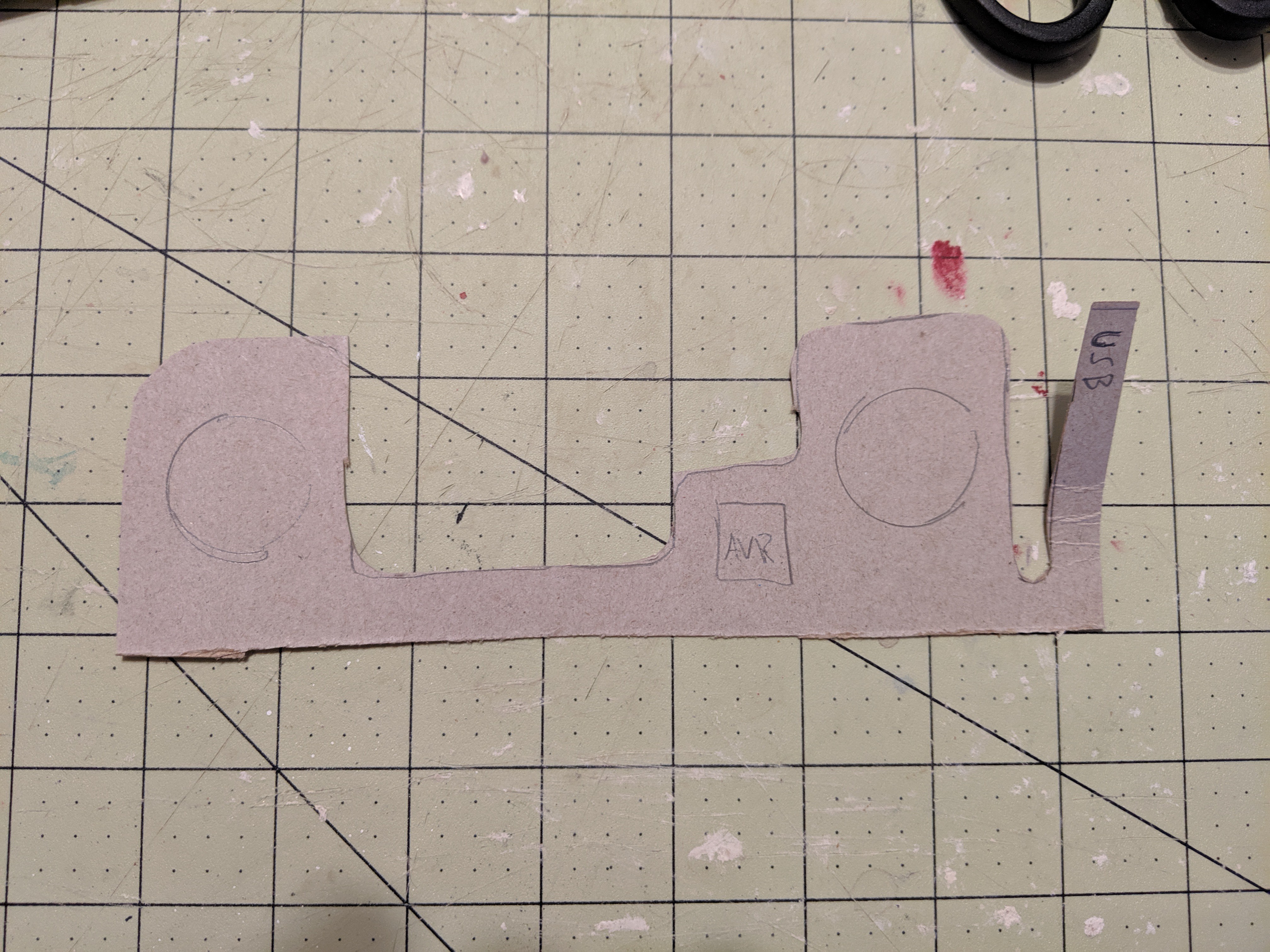
Here's where the PCB will sit in the case. There's actually a lot of ways I can play with the dimensions. The USB connector can move up or down, which will shift the entire PCB, with the width and distance from the phone can change, shoulder placement can change, etc. This will make a good testbed.
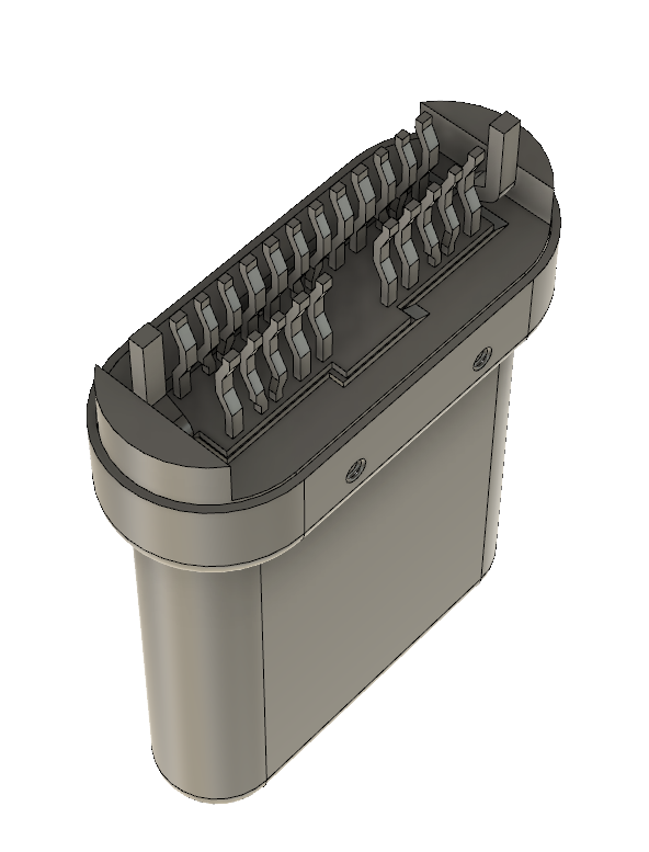
The shoulder button in the corner will bend and slide into a little slot inside the larger slot. I'll have to check the tolerances later to make sure the printer can make the thin tabs that will hold the shoulder button in place. The larger gap will hold the rubber dome. In the future I'll 3d print the shoulder button, maybe even with living hinge built into the case (inspired by the Fusion 360 hack chat).
![]()
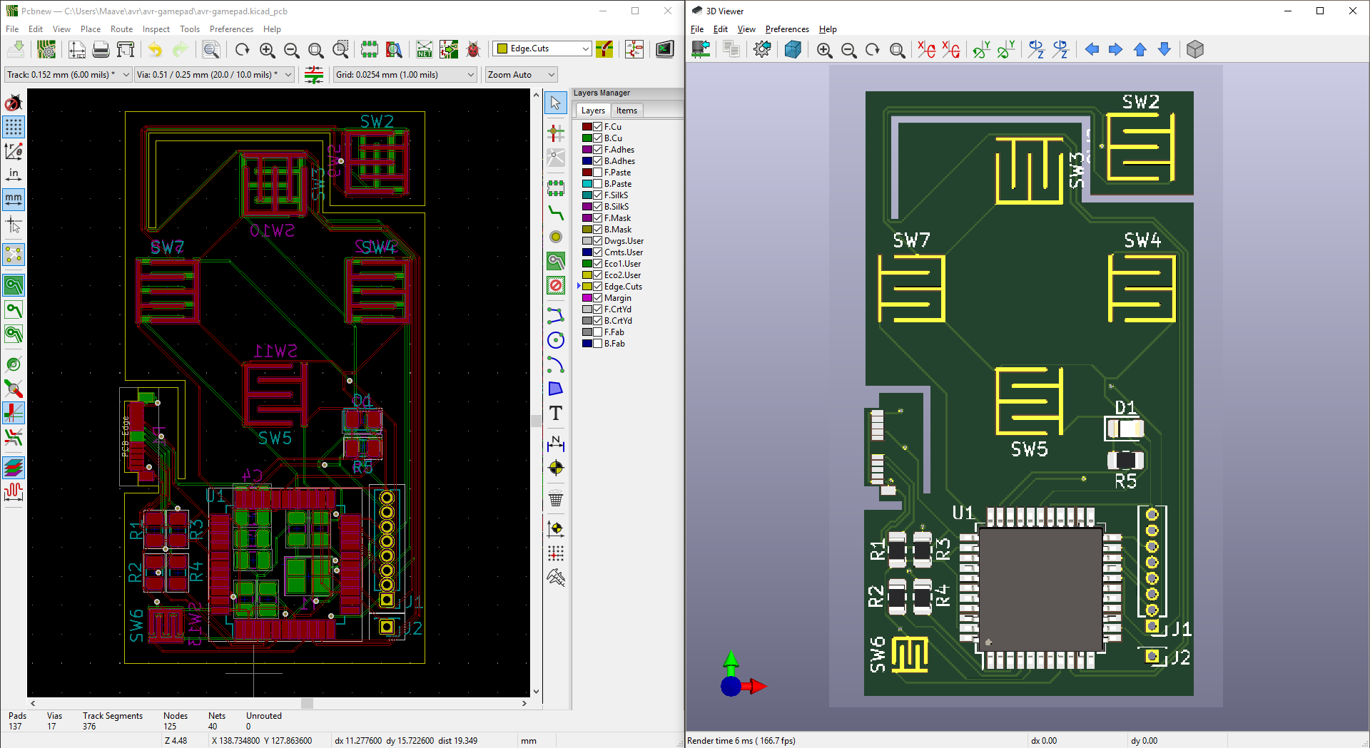
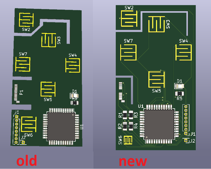
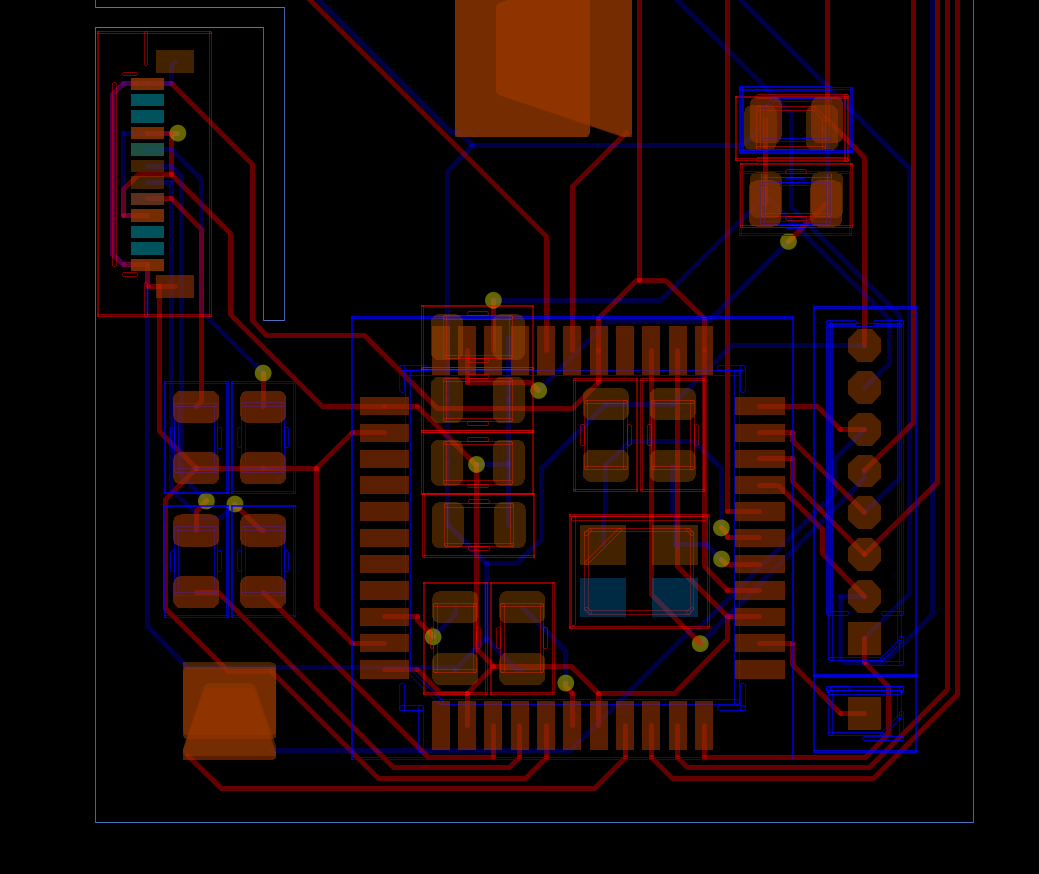
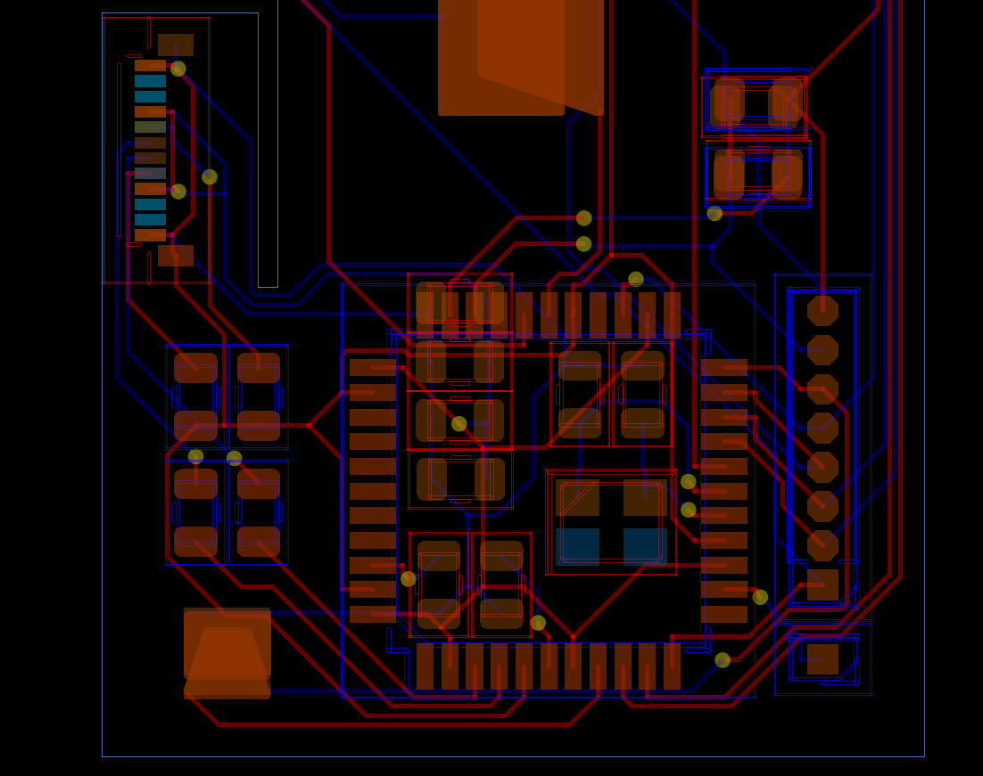
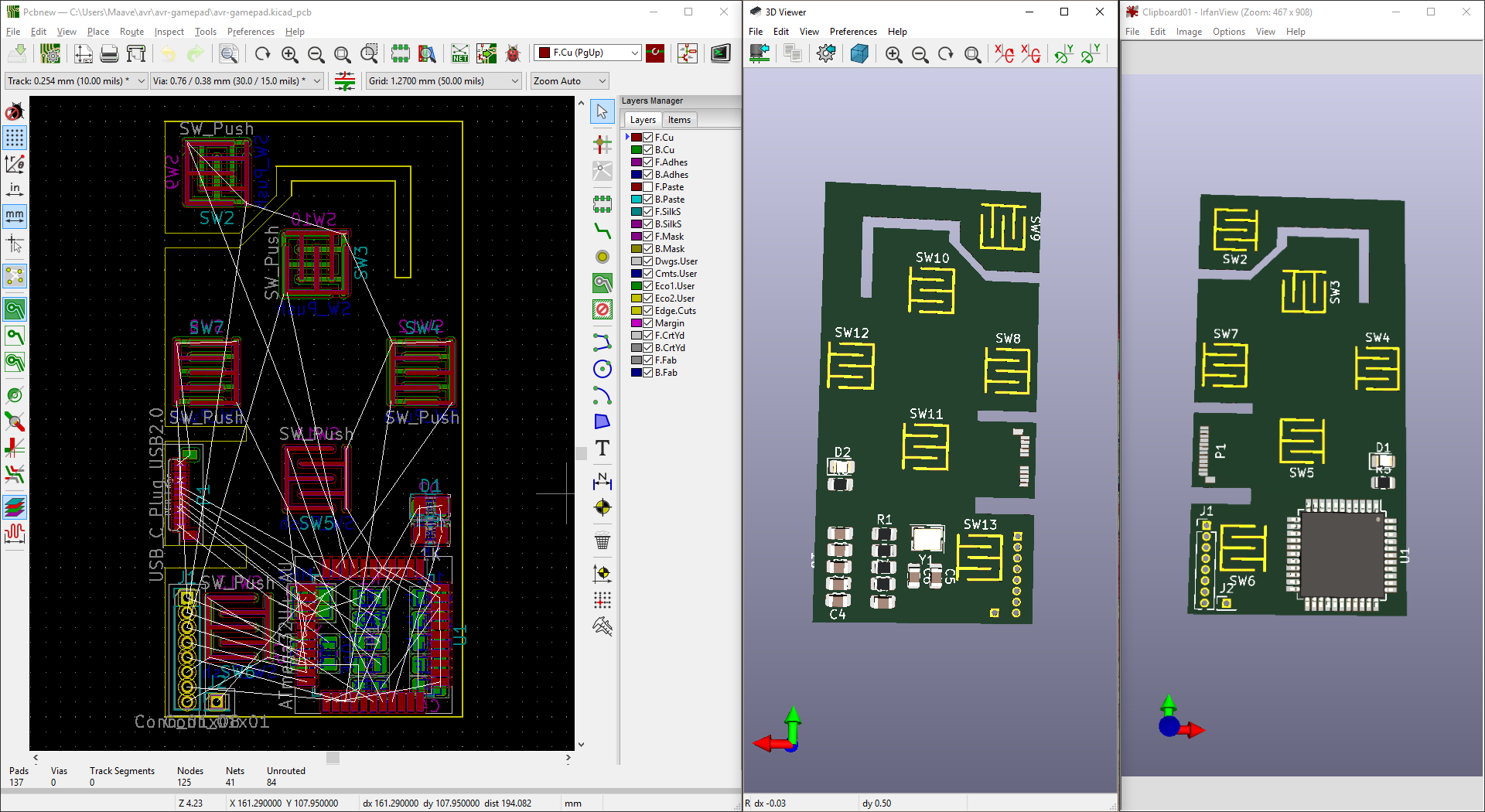
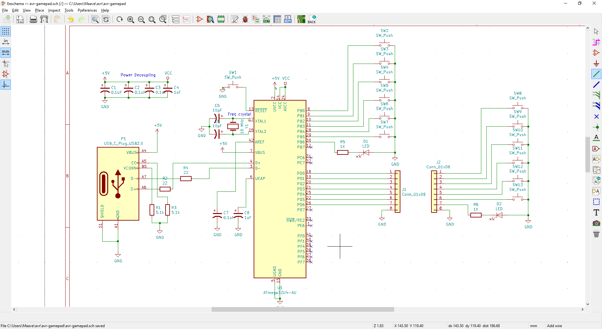
The PCB has some changes. The shoulder button has moved to the other side. The USB-C connector edge cut has been tweaked (reading the docs helps lol) and now it looks more like the PD Buddy Wye that uses the same connector. I realized that it was incorrect when I loaded both models into Fusion and saw the connector clipping through the PCB. After changing the connector I shaved a tiny bit of width off the outer dimension. I tried to change the shoulder button cuts to a single cut (instead of an open slot) but pcbnew complained. Might do that again later.
![]()
The process for getting the model into Fusion is dumb and I need to improve it. Export as VRML, import into Blender, export as STL, import into Fusion. That's the "simplest" way I could find that included all the traces and components. I need to either get 1-click exporting or script it.
I have some ideas for future versions. Like a rigid PCB for the main portion and a strip of flex that acts as triggers and connects both sides. Switching to rigid would reduce cost, fit the USB connector better, and give me a colorful solder mask. I have some sick PCB art planned that uses OSHpark's purple and gold or PCBway's red and gold. The art will remain a surprise until I can pull it off.
Onward!
-
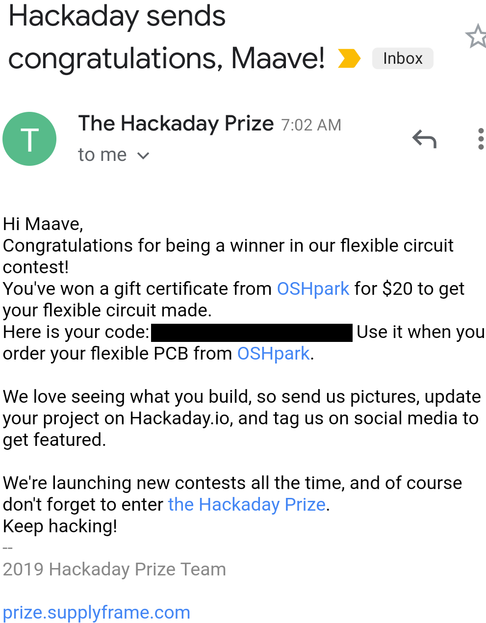
Winner winner, flex PCB dinner
06/18/2019 at 13:09 • 0 commentsHurray! I won a $20 coupon from the Flexible PCB contest. That'll give me 3 copies, enough for 1 1/2 complete controllers. The PCB is almost ready. I'm in the process of 3d modelling the case and sometimes I make minor tweaks to the PCB to fit. I'll try to finalize the PCB and BOM this week and send it off for manufacture.
![]()
-
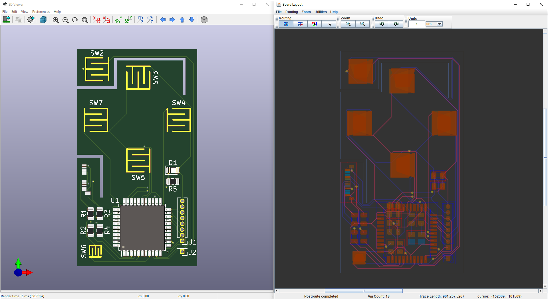
PCB routed, DRC passes
06/04/2019 at 02:03 • 0 commentsWoohoo it's routed! And the DRC passes. I'll post source on Github soon and then start work on the 3d printed case. EDIT: source on github.
Here's the evolution of the layout. I took a screenshot of the bottom half since that's the interesting part. It's fairly easy to move components and then autoroute with FreeRouting. I've shuffled a lot of components, changed the edge cuts, made the board slightly shorter and fatter, and shrunk the start/select buttons.
v0: Bad. Components were roughly placed on the board. I accidentally had 10 mil track width so the USB-C connector wouldn't route.![]()
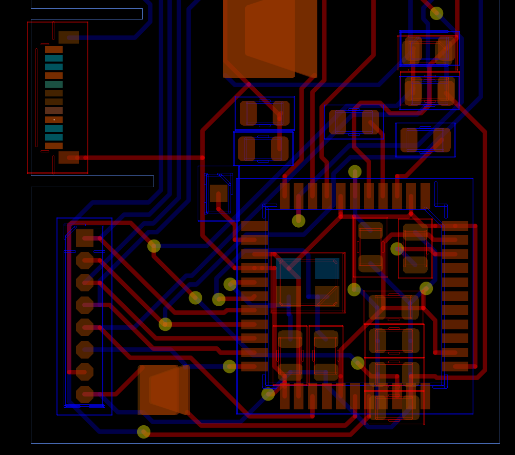
v1: It works. It routes now but it's ugly, the USB resistors are too close to the buttons, and there's very little room for future features. The autorouter found some interesting routes near the USB connector that I wouldn't have thought of (I hope they work).
![]()
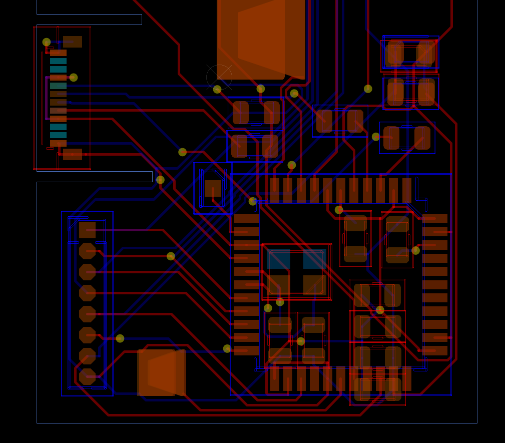
v2: Better. The start/select buttons are in the wrong spot. I wanted the USB power and data lines shorter, and I didn't want them to cut across the tracks for the button contacts. Many of the components have been rotated - I selected the atmega, all the components underneath, and the header pins, then rotated. The flex area for the USB connector now goes down instead of sideways.
![]()
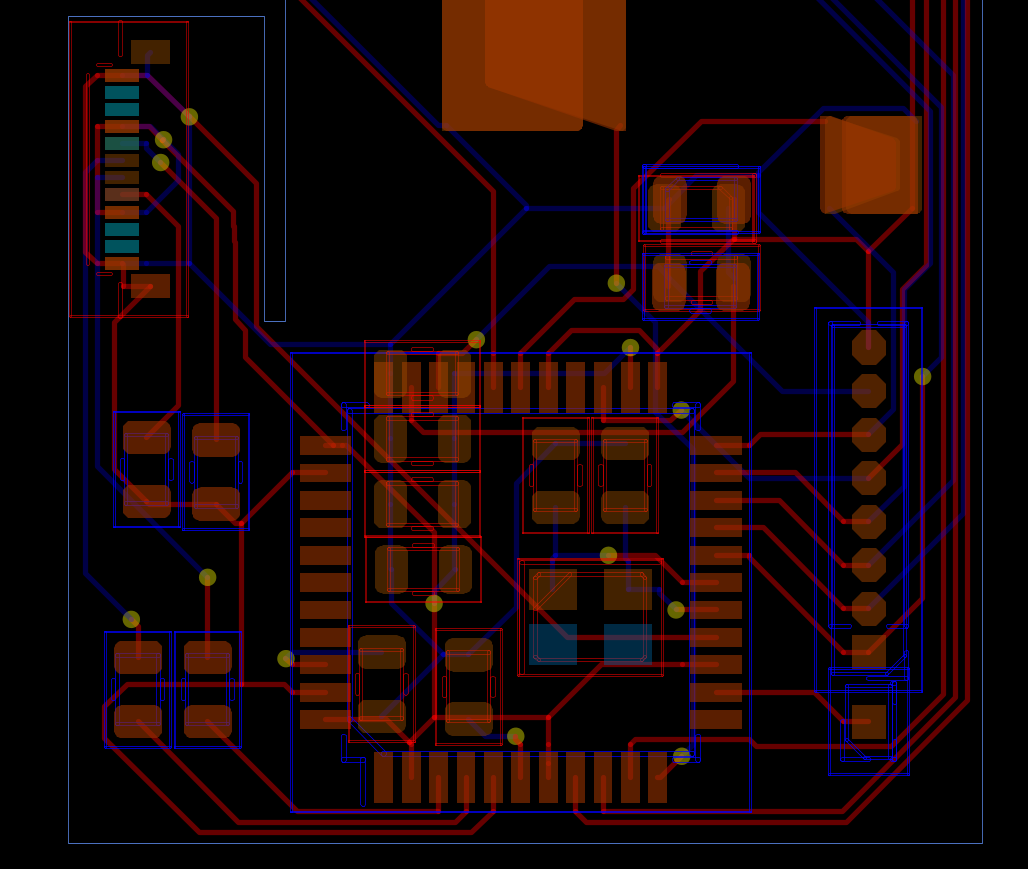
v3: Good layout. I moved the start/select buttons (the smaller contacts) into the bottom corner, moved the components slightly, and reassigned some pins. There's breathing room now so I could easily route analog components (the pins on the left side of the ATMega).![]()
v4: Tweaks for the DRC. This is the last change for now. I adjusted the clearance on the USB-C pads (4 mil pad clearance instead of 6 mil) and barely moved the reset jumper. The autorouter ended up changing a lot of routes but it looks fine![]()
-
Flex PCB progress - barely fits 2sq inches
05/27/2019 at 20:52 • 0 commentstl;dr look at the pictures
Time for physical layout. I did some mockups on cardboard. Fitting into 2sq inches is a challenge. For now I'm going with a 2x1 vertical layout so that I can fit the shoulder buttons, but I could make it shorter and wider or even a 1.41x.141 square.
I opened up a knockoff SNES controller to measure the silicone membrane. One minor issue is that the ABXY silicone won't fit with a 1-inch width layout but the D-pad will. For the first version I'll use a D-pad silicone on both sides. Later I'll look into smaller button sets like GBA, DS, and PSP. I'll also look into dome switches like those used in the 3DS, PS Vita, and Switch.
![]()
![]()
![]()
This is a tight fit. I haven't routed anything yet, just roughly placed the components. The layout feels a little wasteful because I need to leave large open areas for the buttons. The D-pad pivots on a post so I can't put anything in the middle of the buttons (yet). The upside is that this leaves tons of room for silkscreen art and pad art.![]()
There are a number of changes that could save space
-make it shorter and wider
-shrink the start/select button contacts
-use smaller components (currently 0805)
-make the cuts as small as possible (check oshpark specs)
-move the header pins that connects the 2 sides
-adjust the flex PCB running to the L/R shoulder buttons
-make the reset button a jumper (done)
-swap ATMega 32u4 for the smaller 32u2 (questionable)
-use the internal oscillator instead of an external crystal (highly questionable)The only USB-C male connector available in KiCad by default was this Molex 105444. I selected it for now to get the PCB going but this looks like a PITA. Please comment if you have recommendations.
-
Flex PCB brainstorming and schematic progress
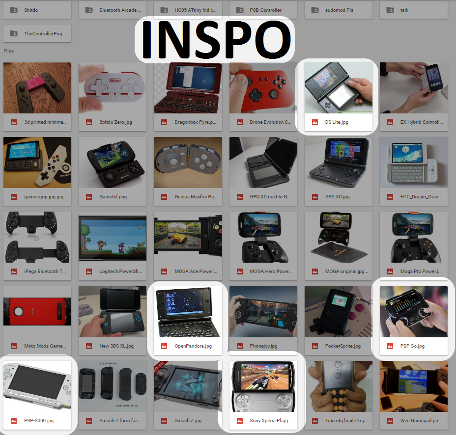
05/21/2019 at 21:05 • 0 commentsOne my ideas was "controls on top", letting my palms rest on the sides of the phone. This layout has pros and cons, and after going over it with my fiance we decided against it. I still like the idea though. Here's a mockup that uses the flexible PCB to accommodate different size phones.
![]()
![]()
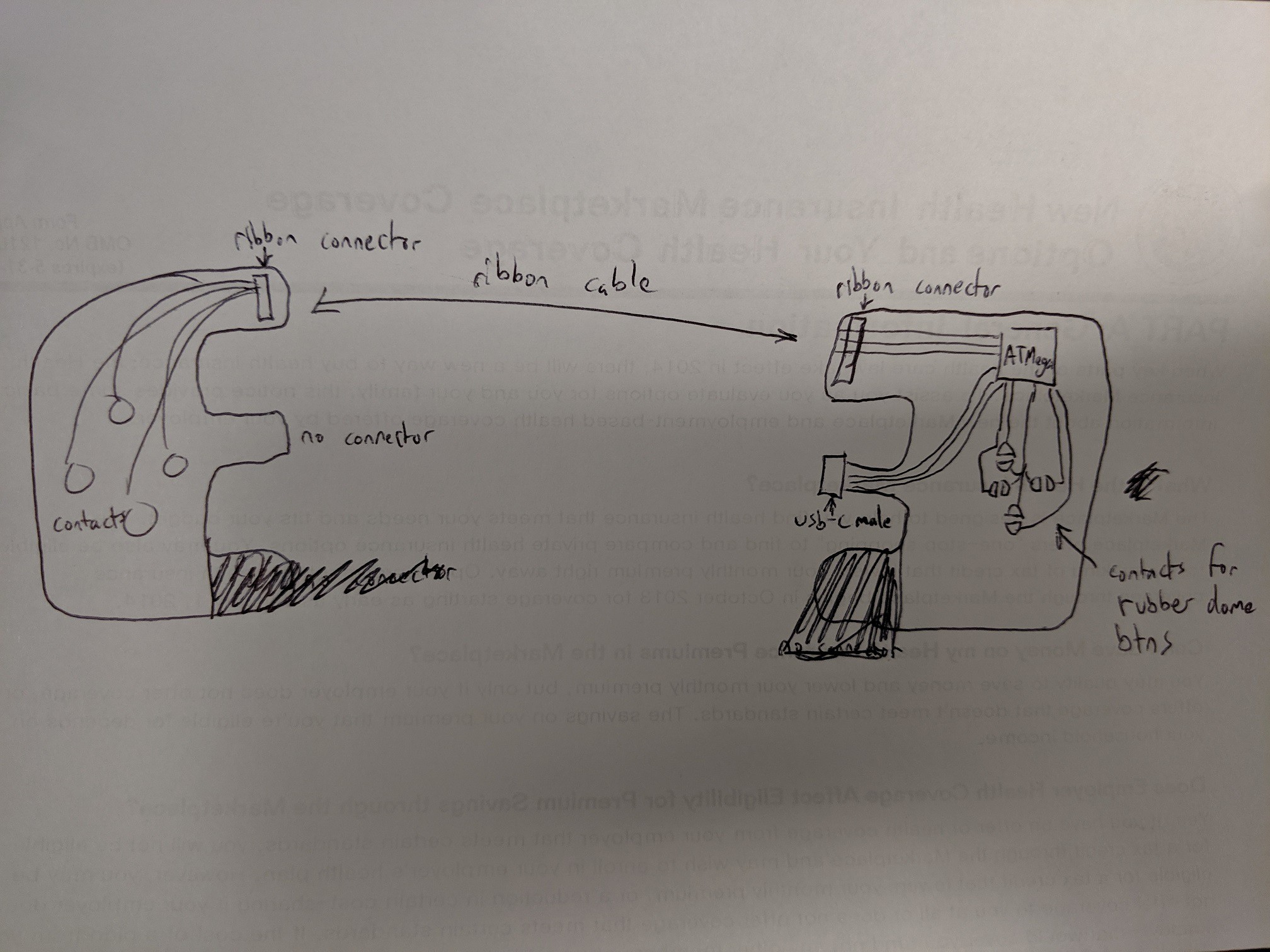
The current plan is a smaller PCB that will make the phone more like a PSP. The two halves will be connected with a ribbon cable, flat flexible cable, or whatever. The prototype will probably use magnet wire soldered on.
![]()
The prize in the flexible PCB contest is a voucher for 3 copies of 2 square inches of PCB from OSHpark. That'll only fit one side of my design. So I'll make this double sided - one side is the D-Pad, the other is the face buttons. Then I can make 1 complete controller and have another half spare. I can complete the spare half with an ATmega and experiment with it.
Finally, here's my schematic progress. Gunna try routing the PCB now.
-
Background and prior attempts
05/21/2019 at 16:51 • 0 commentsI've been spoiled by hardware controls, growing up with things like the GBA, Nintendo DS, and the HTC Dream / G1. The DS was a haven for homebrew and made a nice PDA before smartphones came around. My first cellphone was a used HTC Dream, with a well laid out keyboard that solidly flicked open, physical button on front, and a trackball that was fantastic for RDP/VNC.
This idea started in 2014, playing emulators in the break room at work. By that time I had a newer phone - touchscreen only with a few capacitive buttons on the front. I hated it. I couldn't touch type, couldn't use terminal worth a damn, couldn't easily control a mouse over VNC, and couldn't play action games.
The straw that broke the camel's back was "Prinny: Can I Really Be the Hero?" - I couldn't beat a boss because my fingers kept missing the intangible touchscreen controls. So I started mocking up a controller that would work with my phone.
![]()
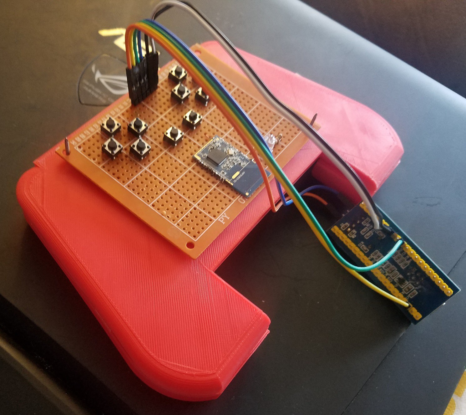
I brainstormed and sat on it for white a while. In 2017 I started working on physical versions. I made one test with an Arduino and HC-05 bluetooth module, and then went to the nrf51822 SoC bluetooth module. Progress halted for most of 2018 while I dealt with life stuff.
![]()
Now it's 2019. Phone UIs and mobile game design have gotten better but playing action games is still putrid. I'm back, full force, ready to slam out a design in time for the Flexible PCB Contest.
Cuttlephone: Gamepad Phone Case
A USB HID gamepad integrated into a phone case.