 Boris Landoni
The robotic arm is also something coveted by the makers, for the fascination it exerts as the first, perhaps most significant, a step towards the construction of a humanoid robot.
The importance assumed in various sectors by this portion of robots makes it necessary to have, in schools and in research and development, skills, teaching and prototypical support to develop projects in the robotics sector. The arm that we propose in this article was designed precisely to take the first steps and experiment and develop robotic applications, clashing with issues such as motion control and related firmware; it is therefore aimed both at hobbyists and at technical schools, where it can become an indispensable teaching platform, and also to designers who need to prototype robotic applications, as well as develop and refine their software and firmware for managing more complex industrial automation systems..
THE PROJECT
Let us, therefore, explain better what the project consists of; it is composed of a mechanical structure in which the electric drives are integrated, as well as electronics that govern the latter to obtain the desired movements.
The arm is of articulated type (also called anthropomorphic) since all the joints are rotating, characterized by 4 degrees of freedom (basic rotation, shoulder movement, elbow, wrist rotation) which, together with the pincer on top, give a certain positioning and orientation ability for small objects.
Let’s start from the mechanical structure, which is the most important part because it is, in fact, the robotic arm; electronics is just the part that controls it. The arm has a structure made entirely of 3 and 5 mm thick laser-cut plexiglass parts and assembled by means of brass / ABS spacers, screws and nuts.
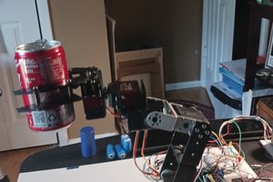
The arm has three joints for up and down movement (it is composed of an arm and a forearm to which a gripper is attached as the hand function) and can rotate on the horizontal plane thanks to a steel ring pressed to a circle of balls, in turn screwed to the base support of the whole; at this base the section containing the electronics is also fixed. The arm can rotate on the support base by 180 degrees and the fifth wheel joins the base of the arm to the support base. The arm and forearm length is 160 mm and the arm can extend in height for a maximum of 27 cm, which becomes 310 on the wrist (the joint on which the gripper rotates) and a good 400 mm considering also the gripper.
The base is large enough to support the extended arm, but if it has to lift heavy weights it must be fixed to the support surface; for this purpose, we have provided four holes for screwing it, for example, to a table, a workbench or a machine whose arm you want it to become part of. The gripper has 45 mm long concave jaws and toothed jaws, so as to facilitate the taking of objects of various kinds.
The arm is driven by two 13 kg/cm servos with metal gears: one controls the rotation of the first section and the second raises or lowers the forearm on the elbow joint. In correspondence with the latter, there is a rocker arm which, thanks to a connecting rod pivoted on the rotating base and to another pivoted on the clamp support, ensures that it remains horizontal regardless of how far it extends or retracts the arm.
The rotation of the arm is 180° and is controlled by a further 13 kg/cm servo with metal gears identical to the previous two; note that for kg/cm we mean the force exerted by the servomotor for a given length of the lever, considered at the end of the lever itself, therefore 13 kg/cm means that the servo exerts a force of 13 kg to one centimetre from the axis of its post, while at 2 cm the 13 kg halves (becoming 6.5) and so on. This is logical since the mechanical system consists of the servo shaft and the operating lever, a disadvantageous lever (power on the fulcrum and resistance at a certain distance).
The support base has a steel ring with one row of balls...
Read more »


 G. Rosa
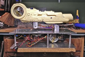
 jeromekelty
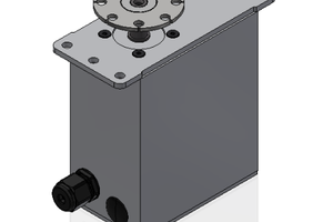
 patchartrand
 j_d_patterson