0%
0%
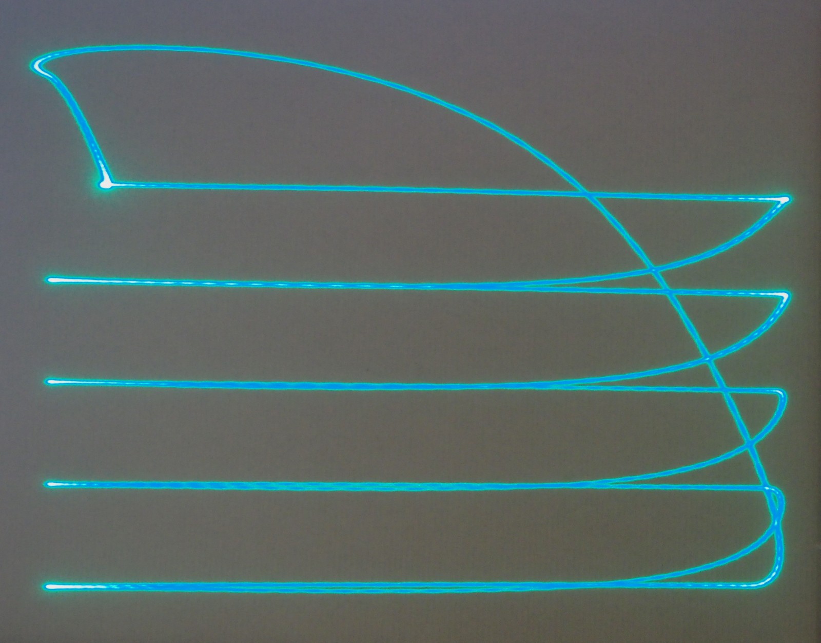
Laser Galvo Clock
Clock projected onto the wall with cheap laser galvos
 Alan Green
Become a Hackaday.io member
Already have an account? Log in.
Just one more thing
To make the experience fit your profile, pick a username and tell us what interests you.
Pick an awesome username
hackaday.io/
Your profile's URL: hackaday.io/username. Max 25 alphanumeric characters.
Pick a few interests
Projects that share your interests
People that share your interests


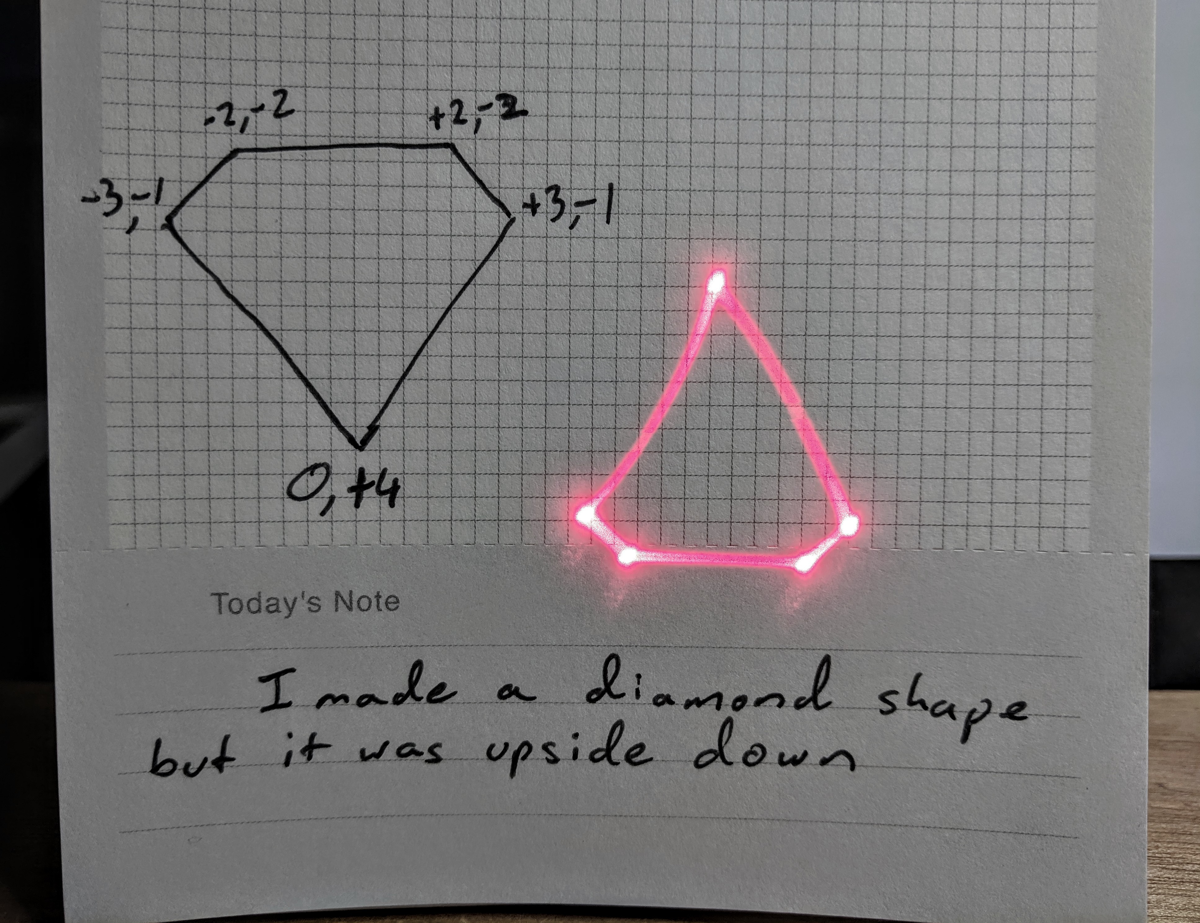


 The picture to the right is a scan of my first planning sheet. While constructing it, I made a few changes, which you can see in the larger image, below.


 David Brown
 Nick Sayer
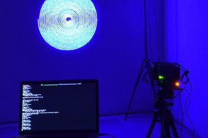
 Owen Trueblood
 Beaglebreath
Excellent, definitely want to muck about with some laser effects soon!