 Adam Taylor
Introduction
Along with vision, two of our most important senses are speech and hearing. In this project we are going to examine how we can use a heterogeneous SoC to implement an audio processing pipeline.
As such we are going to interface with an audio source (Amazon Alexa) and speakers to enable a pass through audio channel before looking at how we can implement additional filtering into this processing loop using High Level Synthesis.
To complete this project we will be using Vivado, SDK and Vivado HLS.
Approach
For this project we are going to be using the KRTKL Snickerdoodle System on Module (SoM) and the KRTKL piSmasher board. The piSmasher mounts the Snickerdoodle SoM and provides a range of interfaces including
- Dual Ethernet
- Quad USB Hosts
- HDMI In
- HDMI Out
- Line In
- Line Out
- Headset In
Of course for the audio processing example we are most interested in working with the Line In and Out Interfaces.
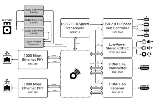
piSmasher Context Diagram (source https://krtkl.com/uploads/piSmasher-supplement.pdf)
The low power CODEC is connected to the programmable logic pins on the Snickerdoodle. Communication between the Snickerdoodle and the CODEC uses a protocol called Inter Integrated Circuit Sound (I2S). This allows us to work with a headset, line in and line out.
If you are not familiar with I2S it is fairly simple protocol it consists of serial data in and out,. This serial data is synchronous to a serial clock, while the channel (left or right) is identified by the LRCLK. Typically the I2S serial data is transmitted in words of either 16 or 24 bits.

I2S Waveform (source TLV320AIC DataSheet)
Logic Design
To create this design we are going to use the following IP blocks within the Vivado project.
- Xilinx I2S Receiver - Set for 16 Bits of Data
- Xilinx I2S Transmitter - Set for 16 Bits of Data
- Zynq Processing System
- HLS IP Core - This will be created using Vivado HLS once we have the initial audio chain passing data.
However, when the I2S receiver and transmitter are added to the design you will notice that both are masters. The CODEC does not have separate transmit and receive I2S interfaces, this means there is only SCLK, LRCLK, Sin and Sout.
As both Xilinx IP both provide SCLK and LRCLK as masters we cannot interface them to the CODEC which only has one SCLK and one LRCLK.
To be able to interface with the CODEC we need first to convert the I2S transmitter to be a slave such that it uses the receivers SCLK and LRCLK.
This option is not available in the standard IP customization flow, instead we do this by selecting the I2S transmitter and enabling selecting Block Properties.
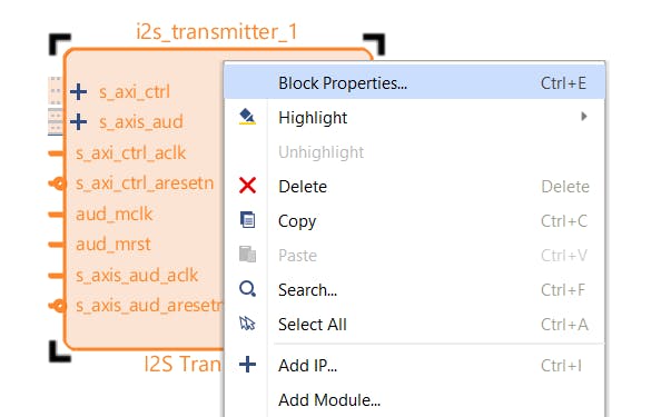
Selecting the I2S Transmitter Properties
Within these properties you should see the under config a option called C_IS_Master change the value of this from 1 to 0.
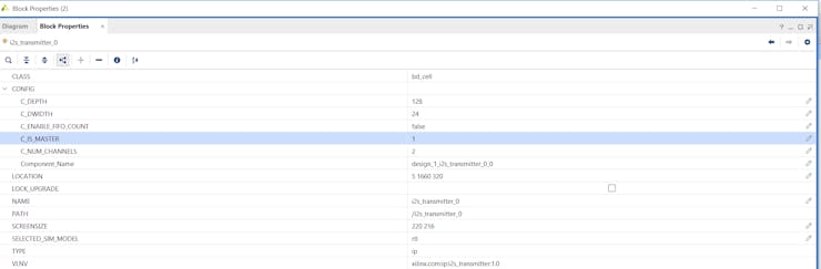
Initial parameters of the I2S Transmitter
Modified Parameters as below

Changing the parameters of the I2S Transmitter
Once this is completed you will see the I2S Transmitters SCLK and LRCLK are now inputs to the transmitter and not outputs.
We can now complete the design in Vivado
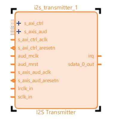
Updated I2S Transmitter Configured as a Slave
We control the CODEC over a I2C link, this configures the CODEC settings and its internal routing.
The I2C pins on the CODEC are connected to the PS MIO on the Zynq, therefore we also need to configure the Zynq Processing system to enable I2C_1 connected to MIO pins 24 and 25.

Enabling the I2C in the Processor System
We are then in position to implement the first Audio pass through design without the HLS Block.
This enables us to demonstrate we can configure the CODEC correctly and that we can pass I2S signals through the programmable logic. For this design we connect the I2S receiver and transmitter back to back. This is simple to do as both blocks use AXI Streaming interfaces internally.
Along with the I2S signals we also need to provide a master reference clock, to the CODEC. This needs to be able...
Read more »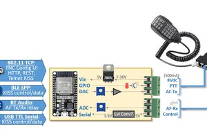
 Ryan Kinnett
 zpekic
 Paul Stoffregen
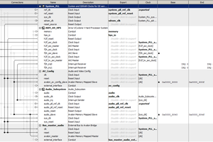
 Bruce Land