 Iulian
Hello !
I was reading a lot of Hack a Day and this site inspired me for nice projects, so I decided to give back to the community with a little project that is easy to make :
Nowadays there are many methods to power on / off multiple devices at same time, like HDMI CEC, HDMI ARC, Viera Link, simpLink ....
Some of these methods are not compatible with all hardware, like in my case.
I own a LG DVD player ( HT462DZ1-D0 ) with amplifier that I use with my Toshiba TV.
The integrated solution provided by LG (simpLink) works with LG TV and this DVD isn't HDMI Cec compatible, and even it was, I use optical in since I use this device only to listen the TV with better sound.
This project consists in reading the Power button of the TV, then use the command to power on the DVD at the same time with TV.
For this, one can use Arduino or Esp8266.
I chose esp 8266 since beside of this project, I want to use the esp remaining GPIO to control some relays (for a LED band behind the TV - The USB port of my TV don't cut power when TV is off, and also use 2 other relays to power 2 lamps in the room) and the other reason of this choice was the ability of the esp8266 to connect to wifi. Once connected to wifi, the courtyard of possibilities grow ( MQTT commands, web control...).
Back to this project, first of all one should read his TV power on code. I used the ESP8266 IR Remote to achieve this.
The library must be installed on Arduino IDE with Library Manager (best choice) or manually : https://github.com/crankyoldgit/IRremoteESP8266
Once installed, restart Arduino IDE and connect your esp device.
I use a Wemos D1 Mini, for his simplicity and reset button on the side of the board. Also 4MB of memory are enough for some later EasyEsp or NodeMCU firmware.
Go to examples and on ESP8266 IR Remote open DumpV2.
Read the comments on the code and do necessary modifications if your Gpio receiver is on other pin that the one that's in the code.
I use a cheap KS-022 ( VS1883B ) receiver. Pay attention that unlike data sheet, the voltage input on this module (the module has 3 pins and one red led which light when signal received) is in the middle. The S mean output signal to Arduino/Esp and the remaining pin is GND.
The 100 uF capacitor is between VCC and GND of the IR receiver, as indicated on the data sheet.
You can use only the receiver if you don't need the module Led as showing reception, as in my photos, but this time the VCC is on the right, ground on middle and on the left is the Signal. Not connecting properly may result in receiver burn.
On the DVD, the things are pretty straight forward. Open it, find the button on the board, use a multi-meter or visual inspection to detect the button GND (important since the octocupler GND must be on this GND). Then solder and fix with tape or hot glue the wires to the RCA female mounted on the back, trough a hole in the metal plate (again, respect the "polarity" of the button, solder GND wire on the external RCA jack, the middle is the V+ of the button)
Back to Esp, once soldering / connecting is done, connect your esp to arduino and flash the code DumpV2 from examples.
Open serial monitor and it should say that is listening.
Push the button that you want to read and serial monitor should give you the code of that button instantly.
Write that code down, the hex one.
Now, in the same dumpv2 code, declare another GPIO pin to use with an octocupler as OUTPUT. I was using the GPIO 13, the 14 is the IR receiver.
Now it's just a matter of doing a conditional IF in the void part of the code. Many if can be made, so some unused button of your remote can become a relay switch of a lamp or a Led strip band on the back of your TV, even a fan control or window blinds (with a RF transmitter or a RF Bridge). Possibilities...
Read more »
 Andy Castille
 Nick Sayer
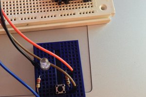
 dougal
 sjm4306