 Nick Sayer
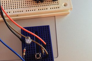
Most of the actual circuit here is the same as the Crazy Clock. The difference is that the tiny is not clocked by an external crystal. Instead, most of the pins are connected to a 5-way joystick (up, down, left, right and "in" or select), and one pin to an IR LED.
The firmware will put the tiny in the deepest sleep possible most of the time. A pin change interrupt will wake up the tiny whenever one of the outputs of the joystick is grounded. The code will then do whatever is required, and once the joystick returns to rest, the tiny will go back to sleep.
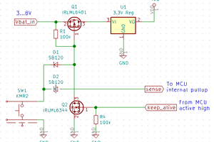
From my experience with the crazy clock, I expect the battery to last a very long time because the NCP1402 is quite efficient at supplying minuscule current draws. The trick is getting the tiny into the state with the minimum possible draw. There are two register bits required to turn the analog-to-digital converter all the way off, and if you don't do the second one, then the ADC will continue to draw 250 µA or so for nothing.
The IR emitter is a standard 0805 SMD part. To make the infrared energy go out the front, the way you'd expect a remote control to work, a light pipe is used to redirect the energy 90 degrees. If the board were put in a case, the pipe's round front would protrude out (or at least be flush with the outside surface).

 dougal
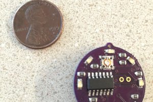
 Christoph
 Iulian
There are some very impressive things that you can visit lg blu ray to learn some informative codes here.