What is it good for?
It is good for compare a working and a not working circuit board, without you have to apply any power to it. A curve tracer show Voltage - Current characteristic of any electric component, like diodes, capacitors, CMOS ICs and many more, which you want to look.
This equipment mostly used in repair purposes
I created three version of the tracker, called Version 1 , Version 2 and te most recent one is Version 3. SUF joined the development, and he is currently designing and testing a new version which will be the Version 4. Below this lets see how each version works.
Version 1
I started develop this version around 2017, when I saw a Huntron tracker at my work and I thought it is not too difficult electronic, but so overprice at the same time.
The Version 1 has just one voltage and one frequency range, so it is a very basic model. The basic idea behind a curve tracer a simple circuit, which input is a sine wave and has some resistor in it. We need a current limit resistor and a current sense resistor.
The other big part is a dual channel oscilloscope with X-Y mode, or like my version I used a cheap arduino pro mini and a display, it is more then enough for a basic operation. I added a function, with the tracker can save a curve on the display and can measure an other component at the same time, so with that you can compare a good component with a bad component.

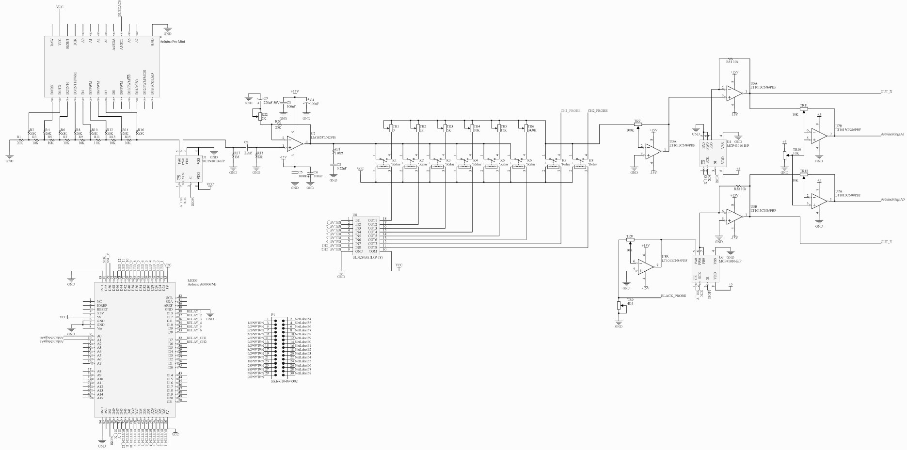
The schematic is a updated version, with some compensation, and modification on it, I could reduce the short circuit difference, so the line is almost vertical on the screen, when the two probe is shorted.
The upper op-amp is the voltage sense (X axis on the screen), the lower op-amp is sensing the current, which is flowing through the measured component (Y axis on the screen).
Some picture about the Version 1


It is not too pretty, but it works well, for a beginner I recommend to start with this, because it is cheap, and after easier to improve.
Version 2
The second version is basically a much closer producte what I really wanted to create, it is based on the Version 1, but I learned a lot from my mistakes. I wanted a multi range and pc compatible version with the stand alone usability without pc, so most of the time I can use it like a independent device, but if I have to I can save the curves to the pc as well. The development was long, it took me more than half a year, and a lot of money as well. I think it is worth all the time I puted in it.
Lets start show what I am talking about.
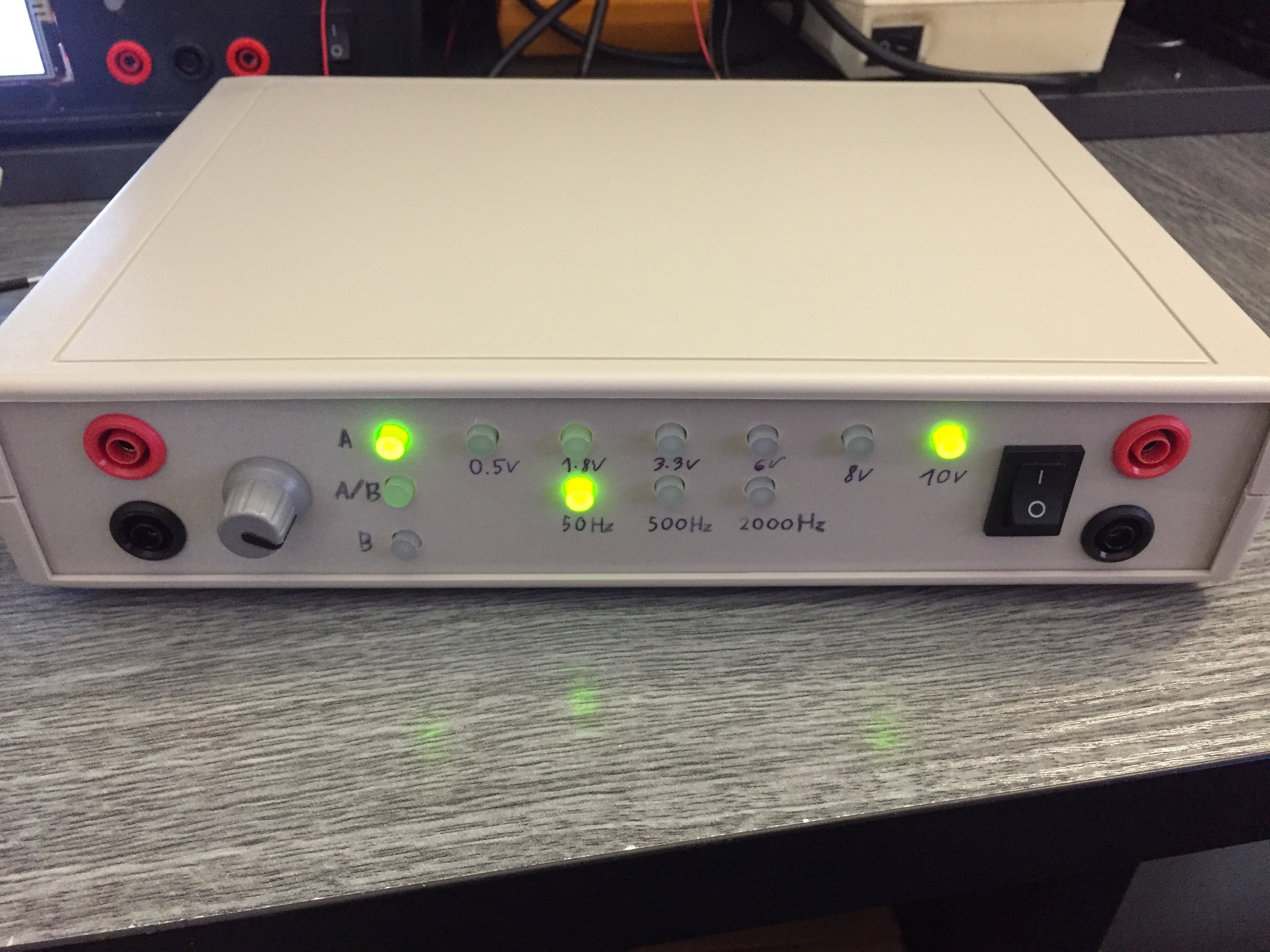
 It has 25 voltage range, 5 resistance and 6 frequancy range. The screen is a 4" mcufriends tft touch screen, but in this operation I did not put any function on the touch screen. The Version 2 has two channel, it is more easier to compare curves at the same time.
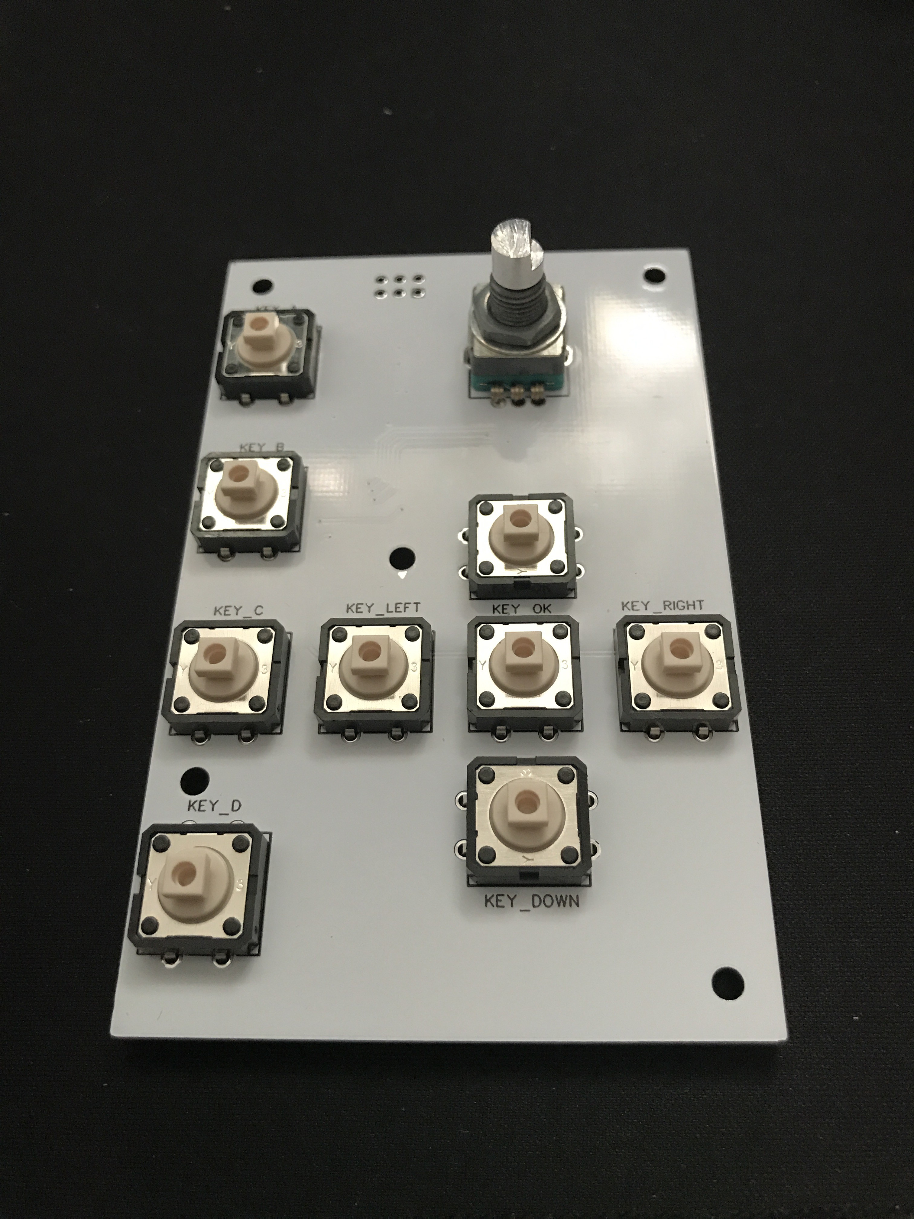
The buttons light up when the actual function selected.
This device is much more complicated then the first version was, so I do not recommand a beginner to try to build this.
More info about this version you can find below at the log section.
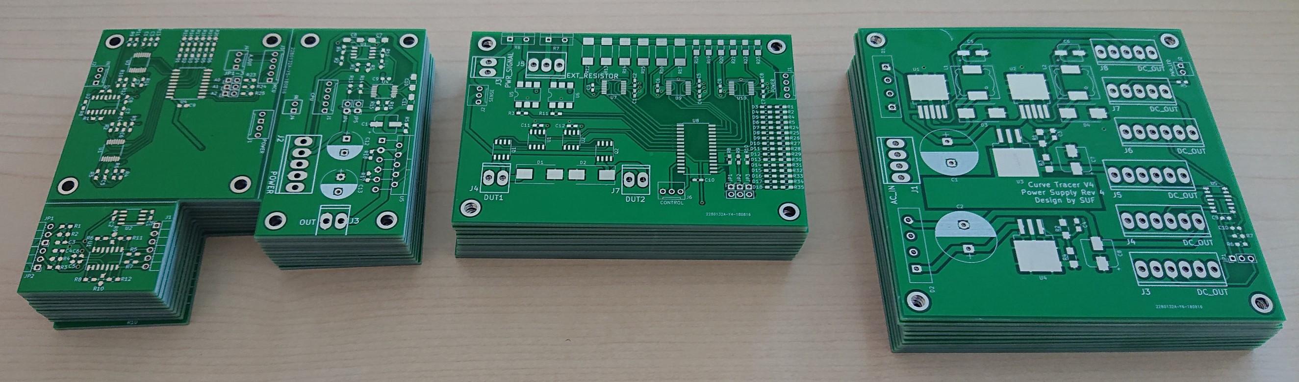
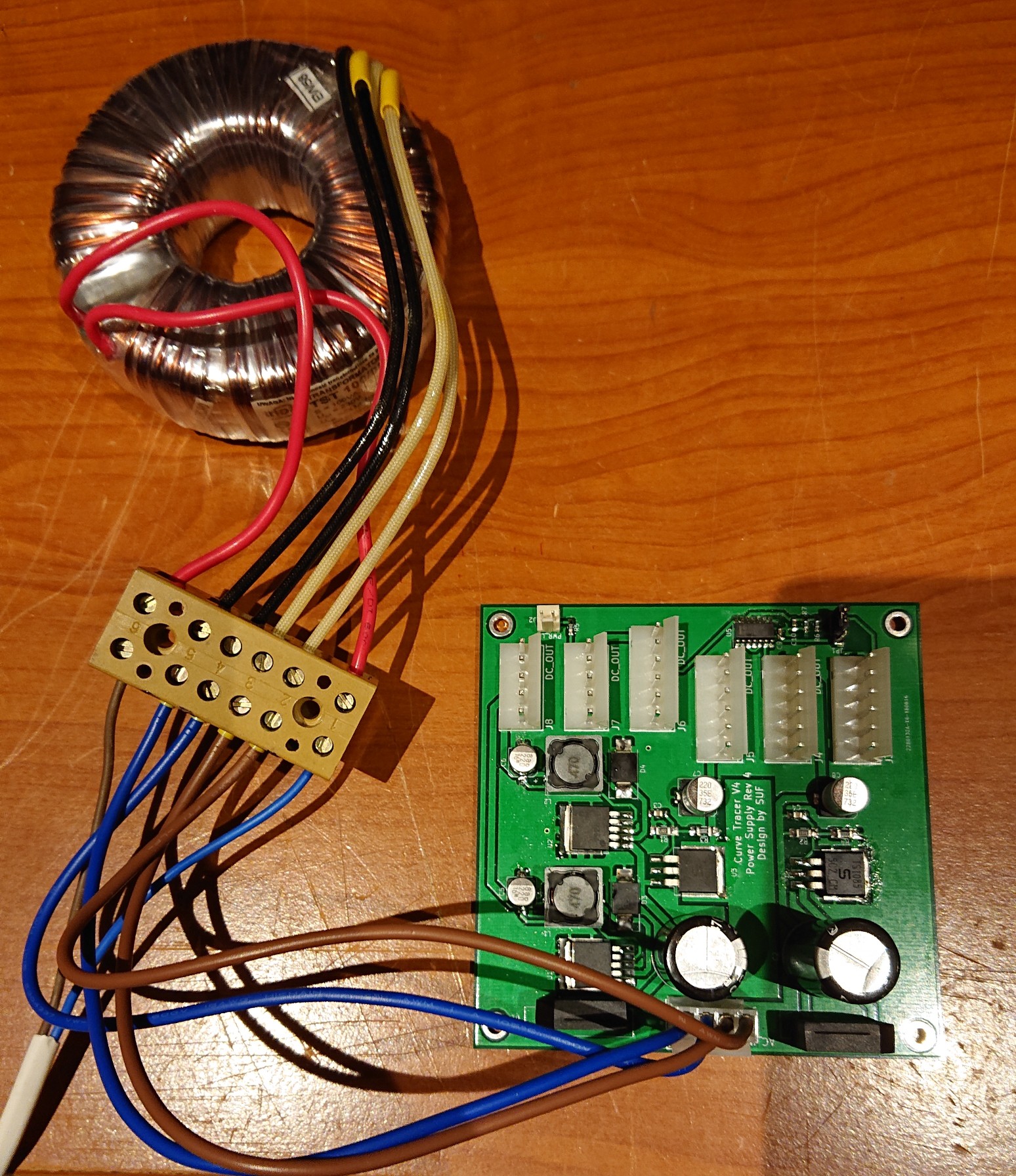
Version 3
I started developing a new version after a couple months the Version 2 was finnished. This will be similar to the Tektronix TR210. It is basically the Version 2 without the screen and any pc connection option. For this version you need a dual channel oscilloscope, but I think it is not a problem for that who is looking these types of instruments. This version also open source, so everyone can modifie and develop it.
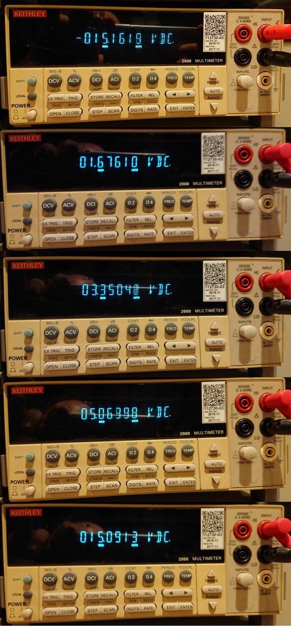
Version 3 have 6 voltage ranges, 6 resistance and 3 frequancy ranges, it also capable to measure two channel alternatly.
You can find the documentation at the download section.
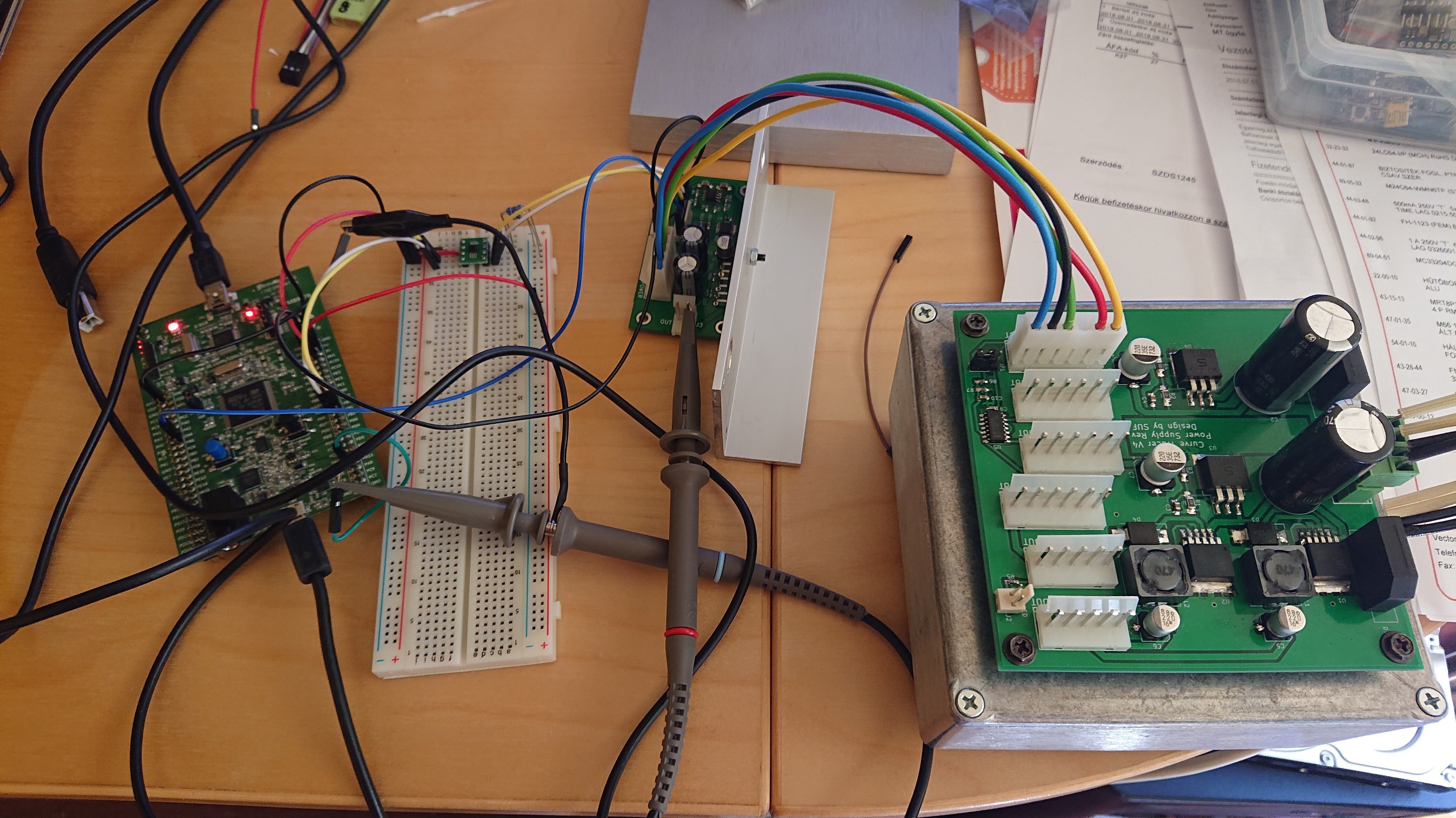
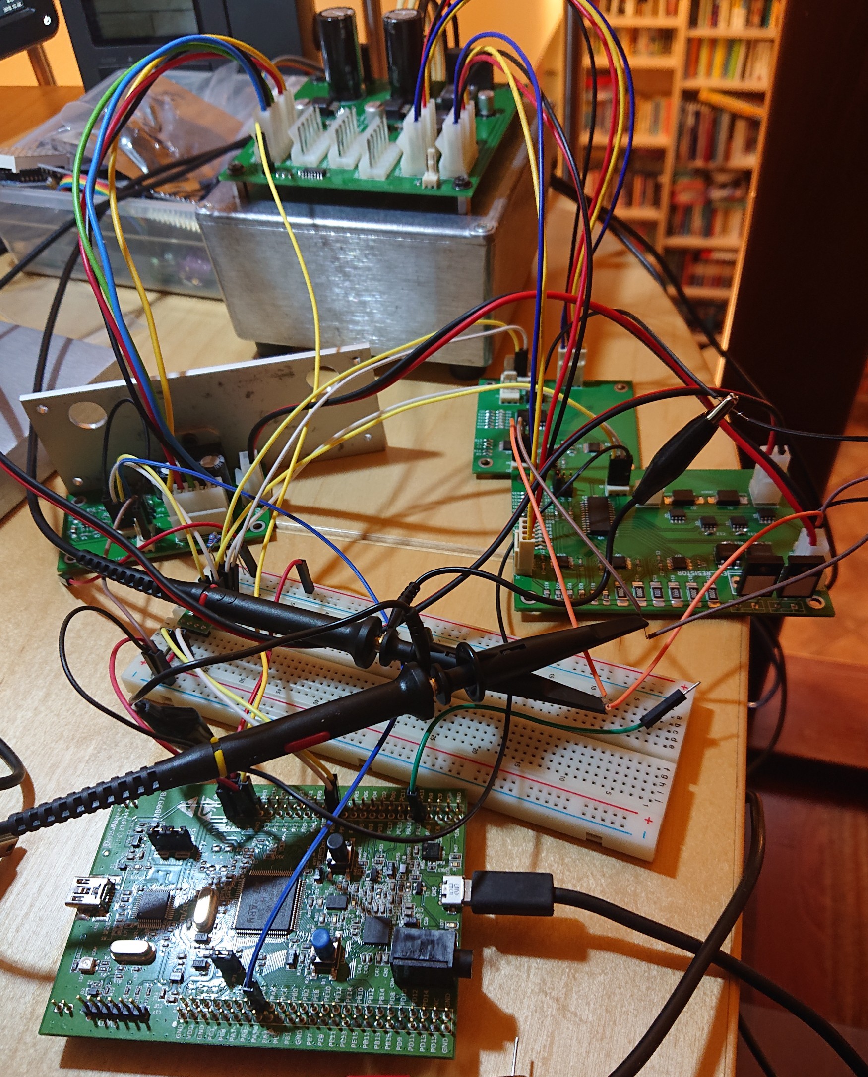
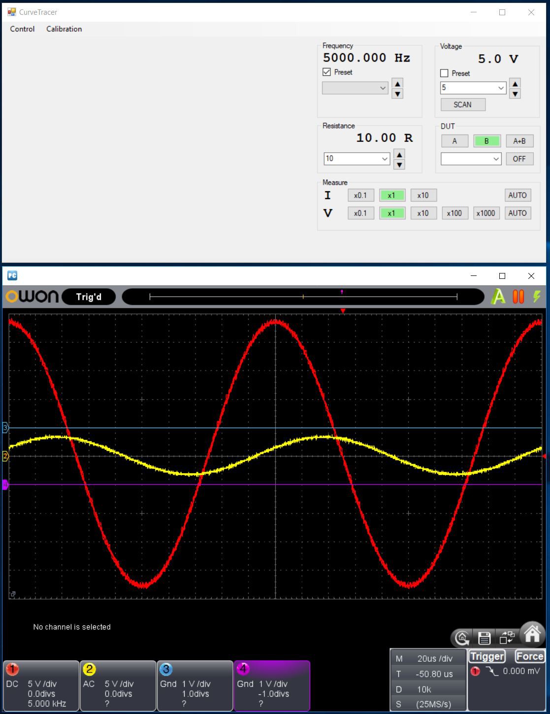
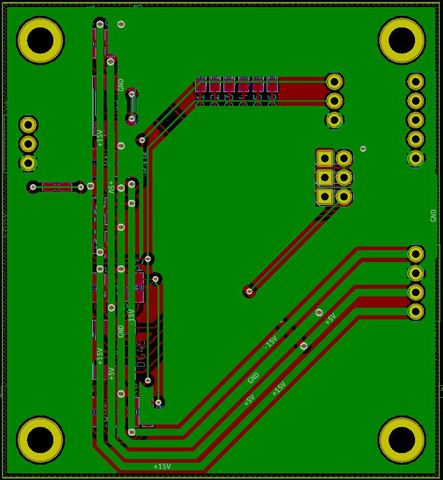
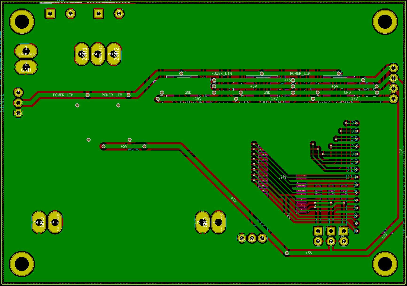
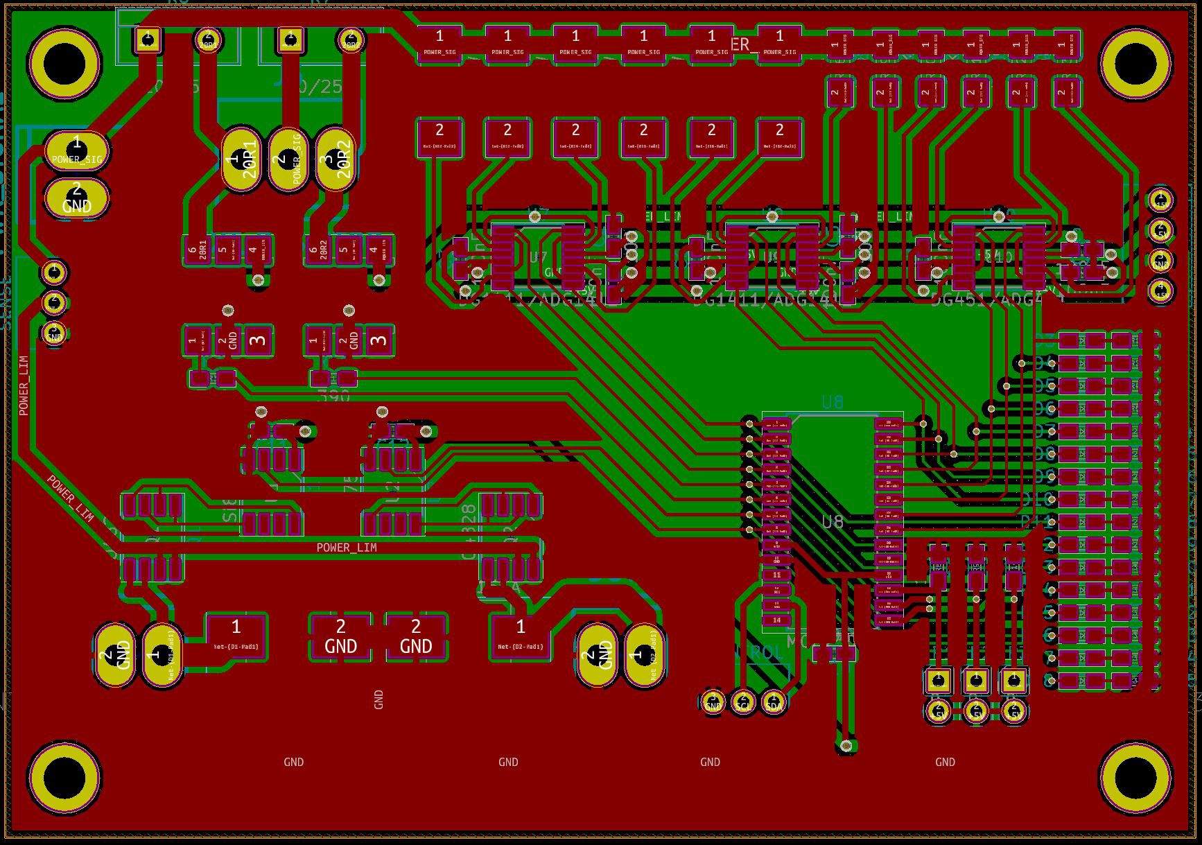
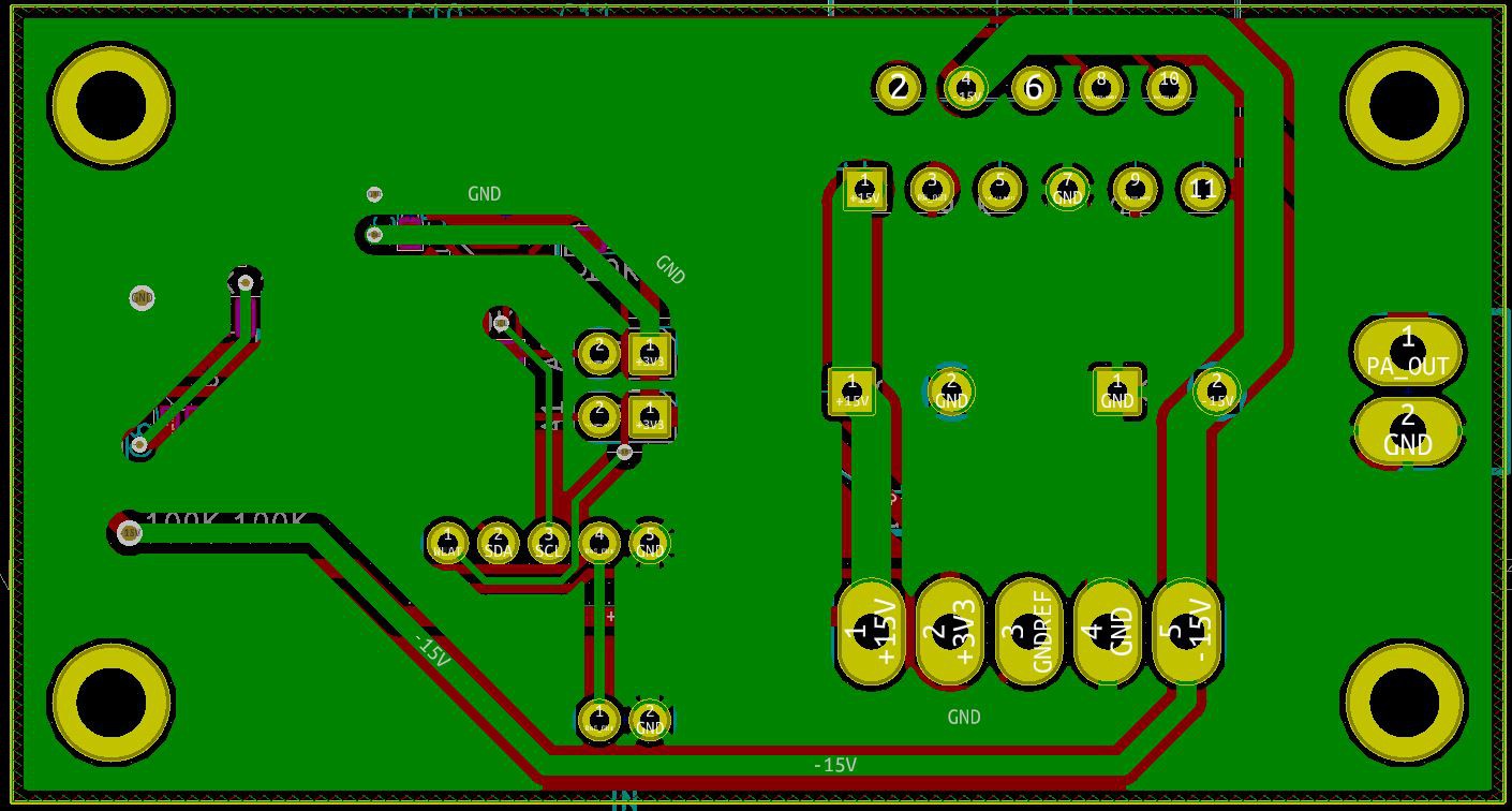
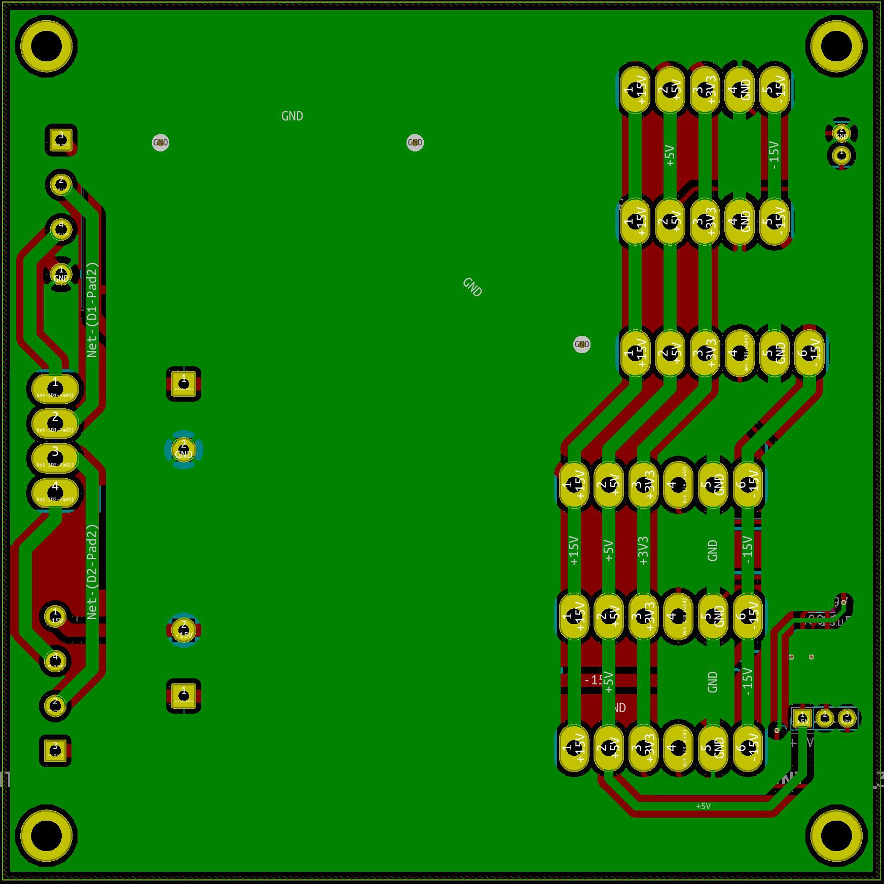
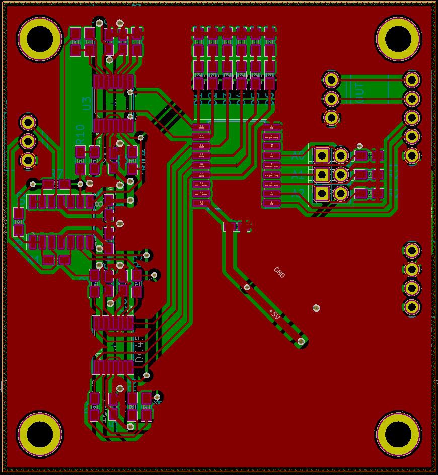
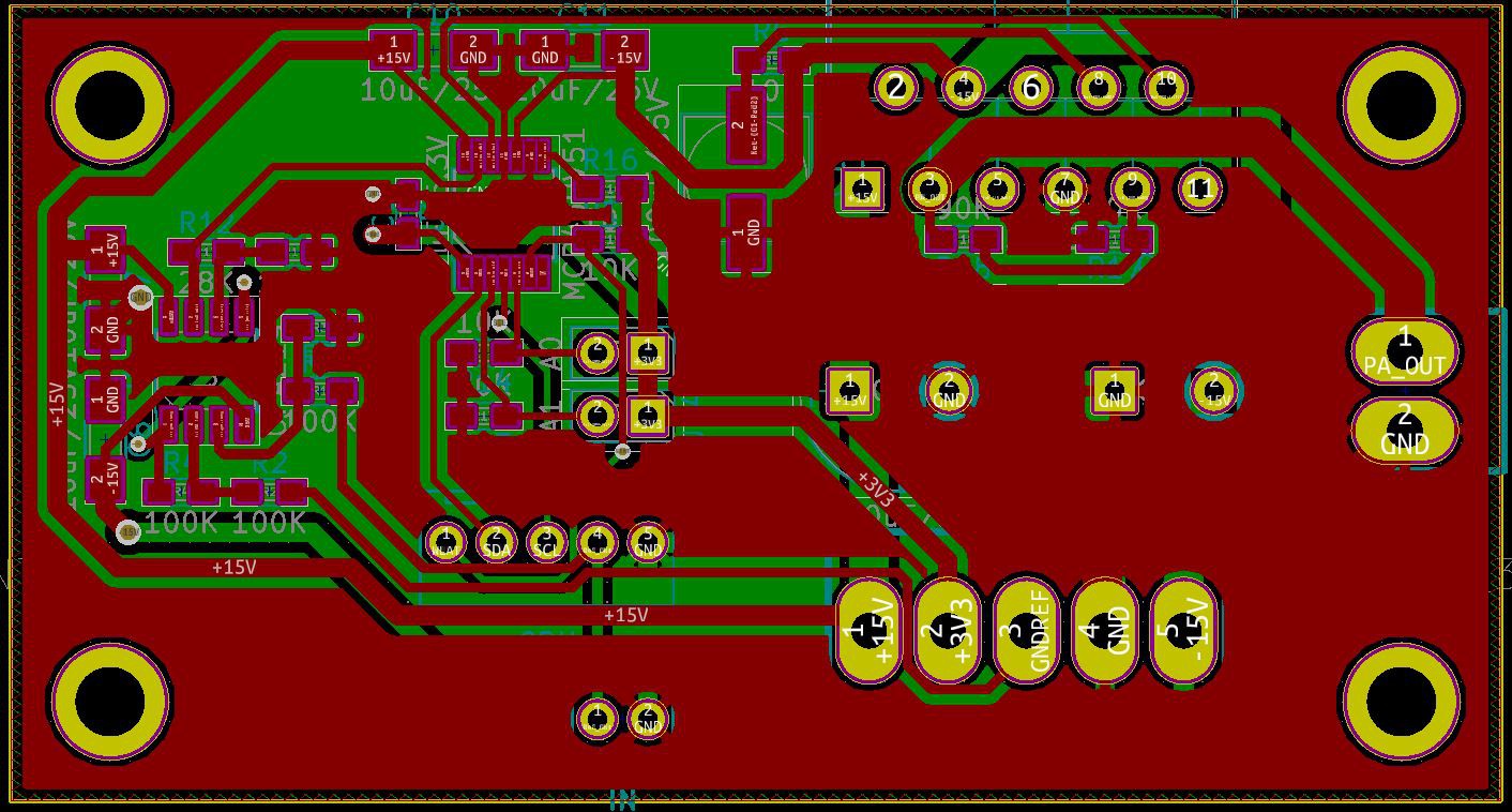
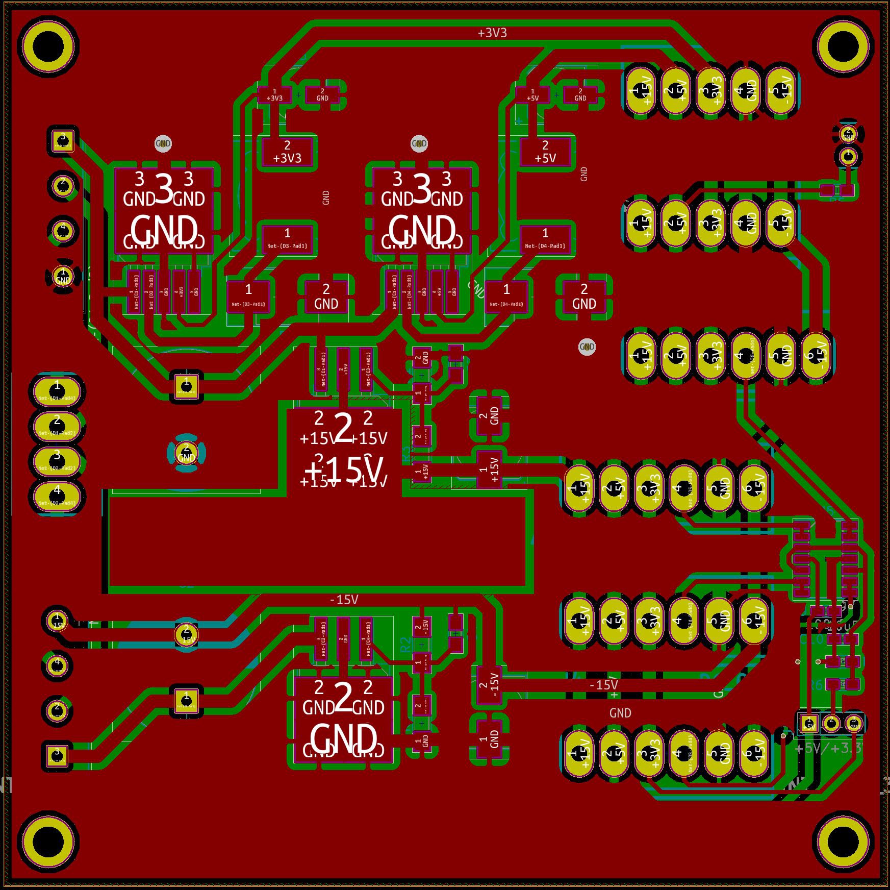
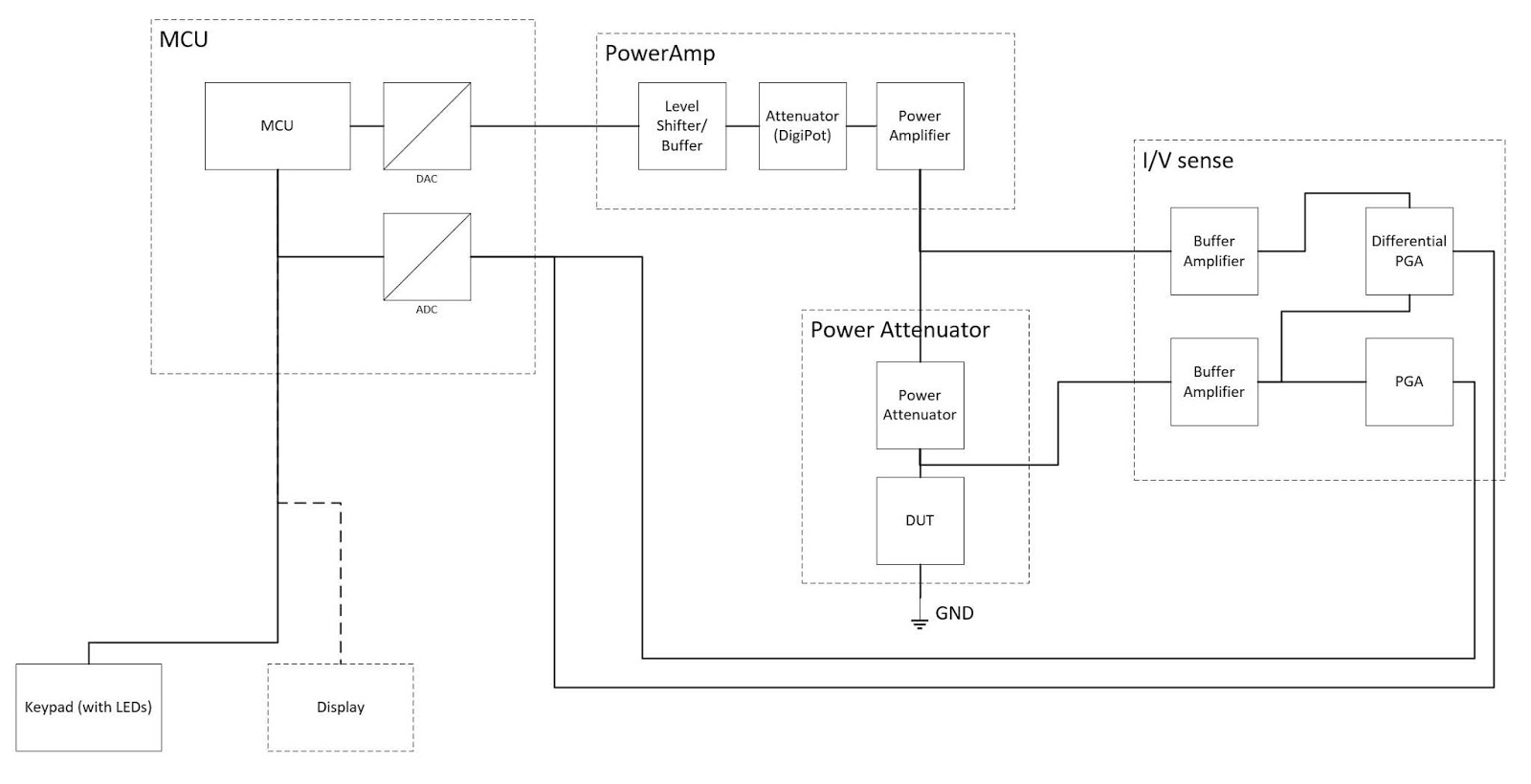
A bit of explanation what the circuit will do. The arduino pro mini at the left acting as a Digital - Analog converter, so it is generating sine wave at variable frequency ranges. Next the signal is going to a digital potentiometer,...
Read more »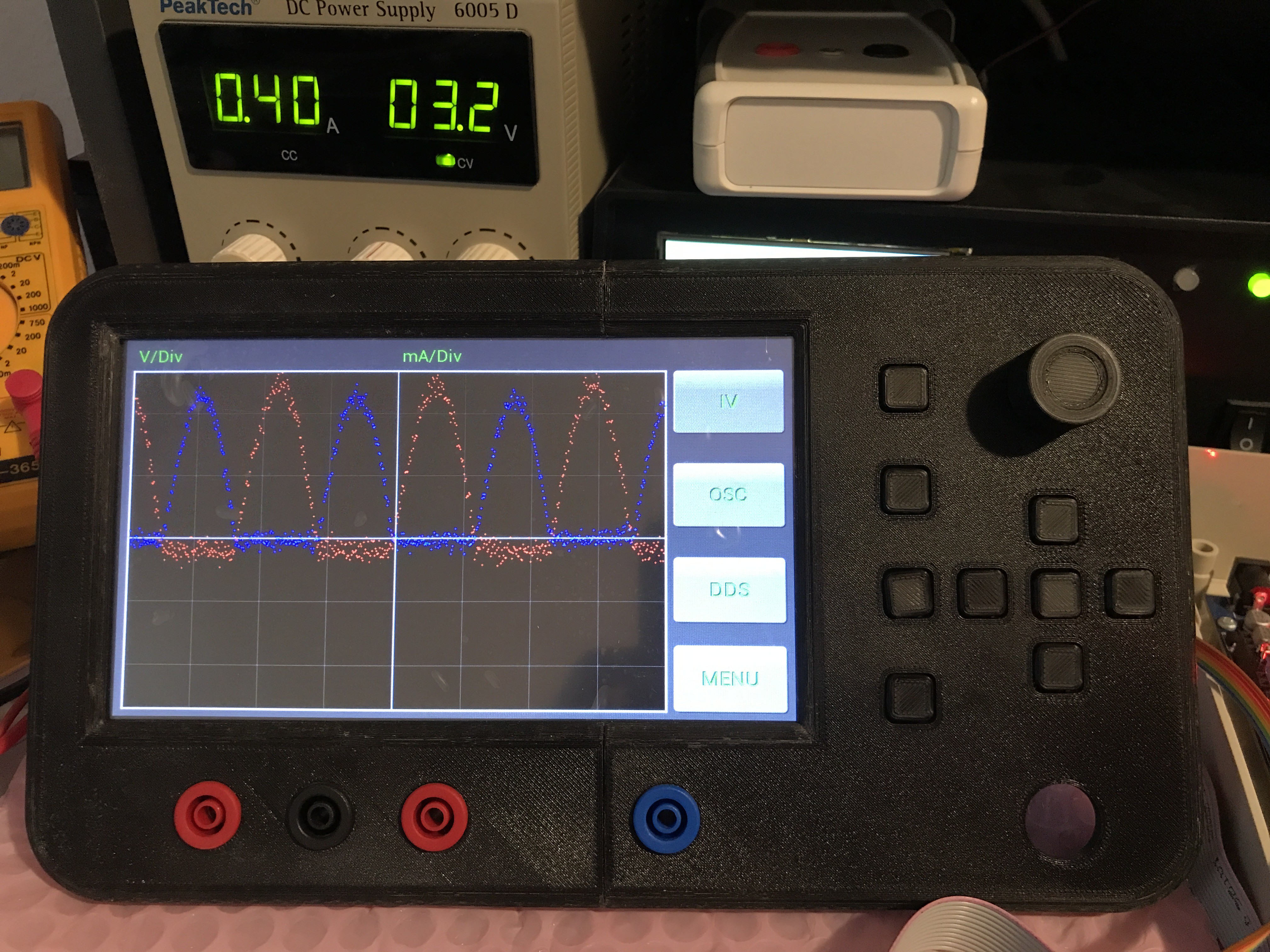


 jaromir.sukuba
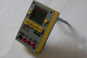
 Martin
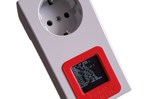
 Sebastian
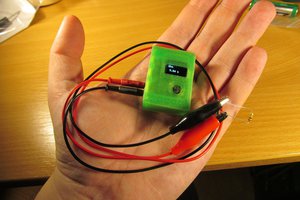
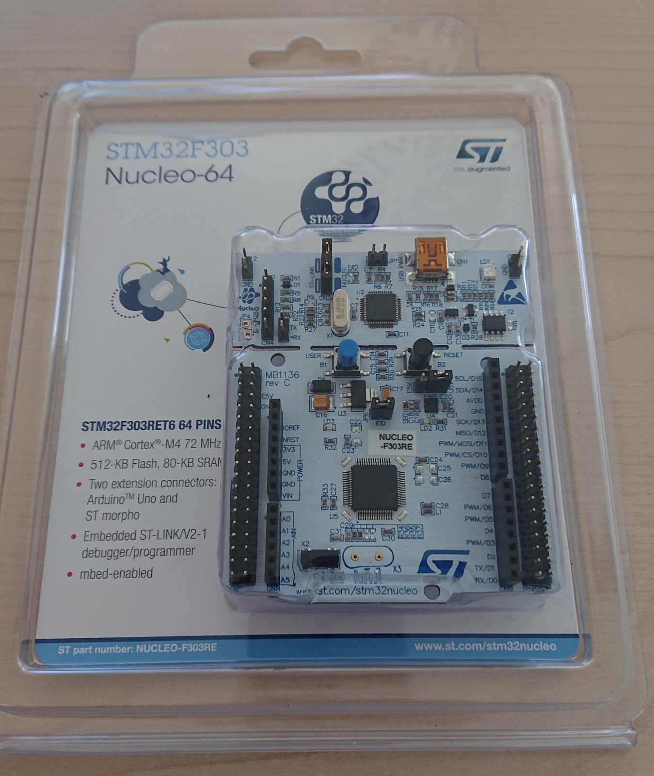
I am interest in building version 3. I have up to now two questions:
1- DUE_DAC0 signal. What the author means by "Arduino Mega output 3 is used as PWM..." There is no Mega out3 pin.
2 - Could not find the Leds & Buttons schematics that the author said was uploaded.
Can anyone help?
rodd414@gmail.com
Thanks