Close
0%
0%

Fetch: A Ferrofluid Display

A 252 electromagnet-matrix that controls Ferrofluid

Public Chat
Similar projects worth following
A student-project at the University of Oslo. We have designed and built a massive ferrofluid-display with 252 electromagnetic "pixels". The display has a 12x21 resolution (the closest we could get to 16:9 on our budget), and is not DONE.

On Applied Procrastination we've shared all the details of this project and hope that it will inspire you to make something similar - or follow your own dream projects.


Background

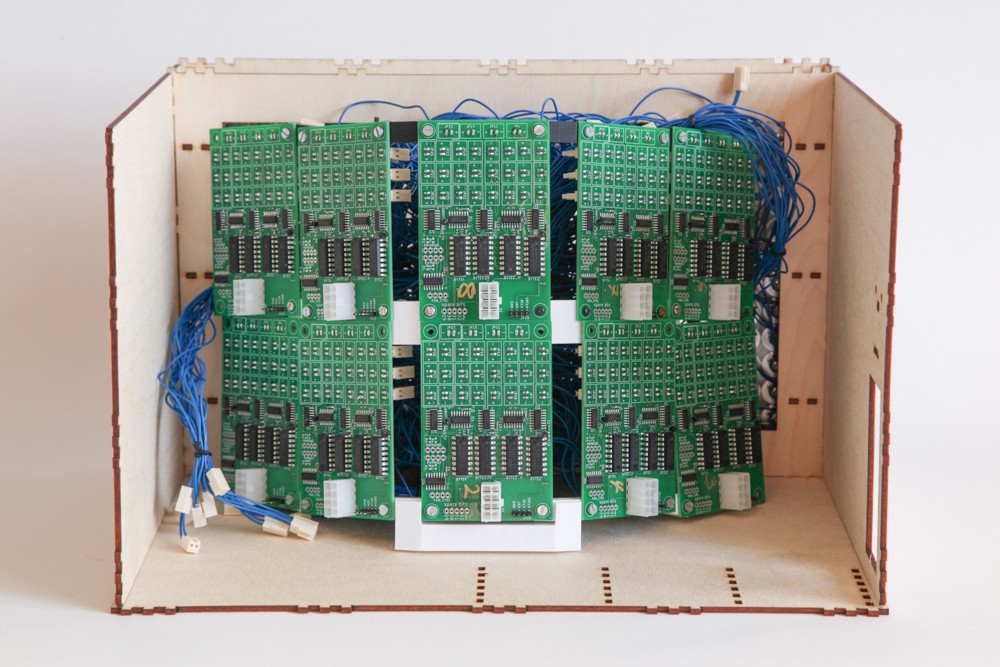
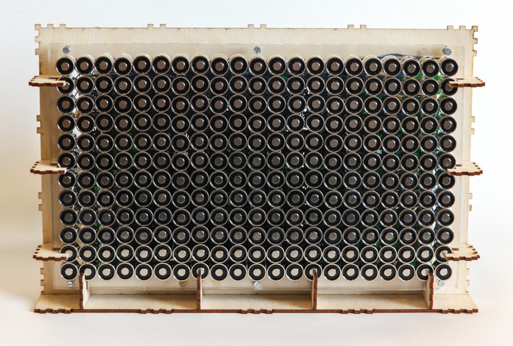
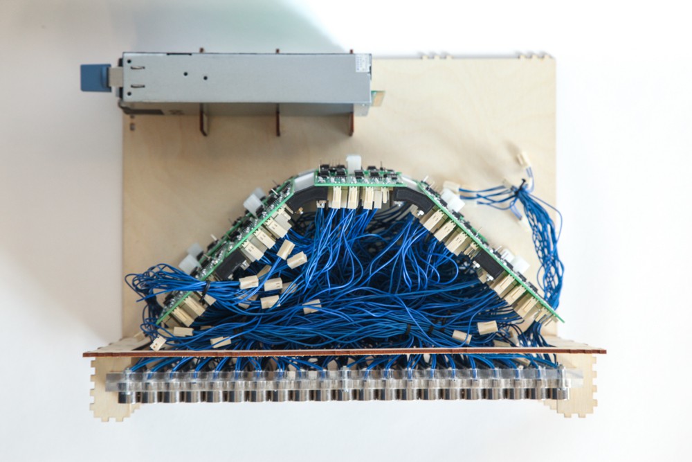
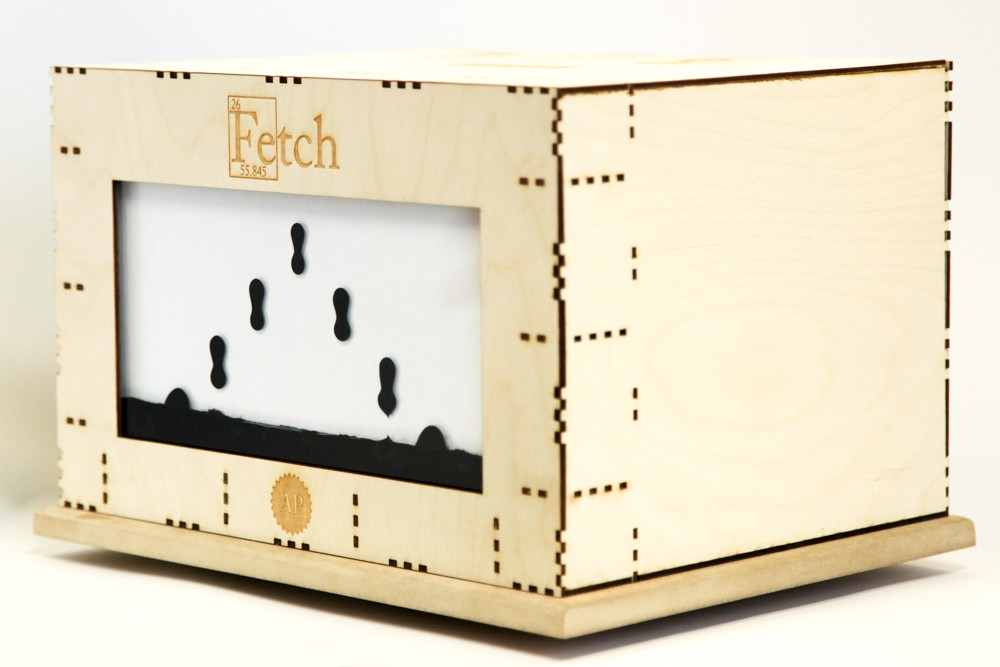
We are a group of students at the University of Oslo, that have designed and built a massive ferrofluid-display with 252 electromagnetic "pixels". The display has a 12x21 resolution (the closest we could get to 16:9 on our budget), and is currently in the final testing phase. The matrix will control ferrofluid and act as a reduced functionality display, meaning it has some limitations.

Most evident is the mechanical time-delays caused by slowness in the ferrofluid itself. It can only be moved "so fast", and it has to be moved up against gravity - meaning it's impossible to magically turn a pixel on out of nowhere. "So fast" is however fast enough that it falls down quite quickly due to gravity. This means we do not get any help from persistence of vision, like normal screens do. In addition, gravity makes sure that if you power a column of adjacent magnets: more ferrofluid will accumulate on the lower pixels, leaving the upper pixels drained. Therefore our system requirements basically state:

1. Each pixel must be individually powered.
2. The system must implement a way of applying different holding force for each pixel.

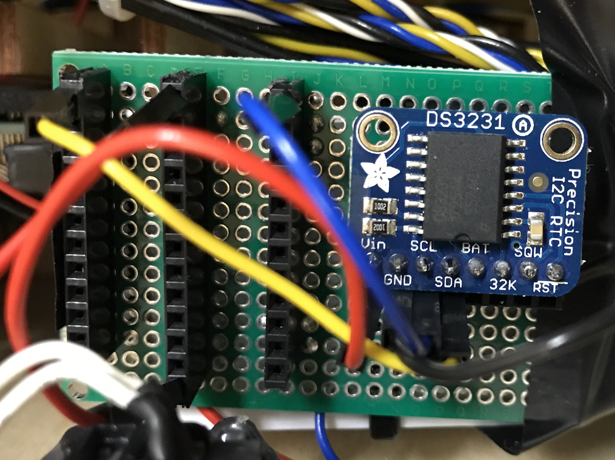
Now, for point 2, the obvious solution is to PWM modulate the signal that powers each magnet (as described in point 1). However, we are not aware of any microcontrollers with 252 PWM pins. We are not aware of an affordable microcontroller with 252 of any pin, really. So, first of all we have to figure out a way to expand however many pins we have to the amount of pins needed. The solution we use are serial->parallel shift-registers. That solves point 1, but snaps us out of the dreams we had about individual PWM functionality... Or does it? Well, the way this has been solved is to implement the PWM in software. This is not optimal at all, because it makes our PWM frequency dependent on the execution time of the main loop. However, with some recent upgrades we made it seems to run fast enough to give us some leeway in terms of frequency-jitter. There's more on the topic of fast code towards the end of this story, but for now, let's take a look at how the project has evolved.

Prototype (Arduino Mega based)

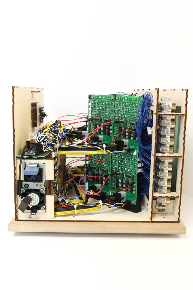
We were not sure how to do anything related to this project when we started, so the only logical thing to do was to start on a smaller scale than the 252-pixel "monster" that we had planned. Therefore we built a smaller, 6x6 prototype, hooked it up to a single driver-PCB (max 28 magnets, so we only connected 6x5 of them) to test how everything worked out. The results were surprisingly good, so we went ahead to commit to a design that we could use in the final display.

When we are done with the full scale display we may revisit the smaller version and make a separate project on that, since it's a lot cheaper and easier to reproduce for other ferrofluid enthusiasts.

Many hours of experimentation

From the time when we saw ourselves happy with the performance of our prototype to the point when our full-scale display was fully assembled a lot of time was spent experimenting with everything from circuitry to the actual ferrofluid tank itself. All of this is documented on our YouTube channel, and if you're interested in making your own ferrofluid display, we highly recommend that you check out those episodes, as we try to share all the pitfalls we've discovered.

Electronics Assembly and Full Integration Testing:

In our most recent video we integrate the full system and test it after first having assembled and tested the electronics.

Everything is open source, and the files can be found below. However, we do not recommend anyone to attempt to rebuild the project in its current state. The electronics especially require a big revision (version 2 will be started later this fall).

Code Optimization

As was evident in the video above, and as we discussed earlier in the article, the Arduino Mega is starting to get a bit overwhelmed by how we handle everything sequentially....

Read more »

FetchControllerV2R2.brd

Newest version of the controller PCB!

brd - 3.93 MB - 08/25/2021 at 18:12

Download

FetchControllerV2R2.sch

Newest version of the schematics!

sch - 296.85 kB - 08/25/2021 at 18:12

Download

Applied-Procrastination-Fetch-Driver-Circuit-v1r2.sch

Schematics (we don't recommend anyone actually using this design for anything... except as a bad example)

sch - 490.75 kB - 08/10/2019 at 11:40

Download

Applied-Procrastination-Fetch-Driver-Circuit-v1r2.brd

PCB design (we don't recommend anyone actually using this design for anything... except as a bad example)

brd - 521.76 kB - 08/10/2019 at 11:40

Download

  • 1 × Teensy3.6
  • 252 × 15/20mm Electromagnets
  • 1 × 1200W HP Server PSU
  • 10 × Custom PCBs In V2 the number of PCBs will be changed to 12
  • 1 × Glass tank

  • Fetch V2 - Massive Hardware Upgrade

    Applied Procrastination08/24/2021 at 17:12 0 comments

    We've upgraded the Fetch hardware drastically! We are super excited to finally share what has been going on behind the scenes on this project since before COVID hit and slowed down our progress. First, have a look at our latest project update video, and then dive into the technical details below.

    Project Update Video

    Technical details

    Why redesign?

    When developing the first version of Fetch we quickly encountered a few problems that could only be solved with a complete PCB redesign. We had made the electronics too generic, and hadn't considered actual integration too thoroughly. So, when we actually attempted to attach wires to it for the first time, we soon realized that the wires weren't long enough to reach where we wanted them. Additionally, since we weren't quite sure how we wanted the software architecture to be, we implemented a lot of features that were more in the "nice to have" category than in the "need to have" category, resulting in an overall bulky design. 

    Version 1 of Fetch
    The first version of Fetch was way bulkier than necessary due to poor PCB design

    Apart from a poor form factor, we also soon discovered that we needed to be able to control the magnetic field strength of each individual electromagnet. The reason that this is necessary is because gravity will pull the ferrofluid down towards the bottom magnet if several pixels are ignited in the same column. The simplest way to control the magnetic field, without having to deal with any additional complex adjustable current circuitry, is by pulse-width modulating (PWM) the supply current that is fed to the electromagnets. We didn't really have a good way to do this though, as the PCBs were based on shift registers that parallelized a stream of serial data in order to open or close gates in ULN2004 Darlington transistor arrays. This means that, if we wanted to implement PWM, we had to do it in software, and the software would be highly resource consuming given that there is a lot of serial data to shift out in order to even get close to a decent PWM frequency. 

    Design requirements

    So when redesigning the board we had much stricter design requirements, both in terms of form factor, and in terms of necessary features. 

    • We wanted one single board controlling each row of electromagnets to simplify the code (and we conveniently had the same number of outputs on our PSU as rows in our electromagnet matrix, which steered us towards one board per row rather than one board per column). 
    • We wanted the board to have a thin and wide form factor so it would fit behind the electromagnet matrix and all the wires would reach their dedicated connector.
    • We wanted to use an IC that could handle PWM for us, preferably through an actual serial protocol rather than just bit shifting.
    • We needed to keep the things that worked well in our previous design (such as an alternating pattern of electromagnet polarities designed into the boards rather than having to manage electromagnets with different polarities decided by their connector orientation). 
    Comparison
    A comparison between one of the 12 new PCBs (bottom) and one of the 12 old PCBs (top)

    The trick

    Three of the mentioned requirements were easy to implement, but finding a PWM capable IC that could provide enough current for our needs proved more difficult. After pondering a while we realized that there are a ton of PWM capable ICs in the LED driver segment. 

    Maybe we could just use an LED driver to power our magnets? The problem with that idea turns out to be the maximum current rating. LED drivers are typically not rated to sink more current than what is necessary to turn on an LED or two. While a normal LED can consume a fair bit of current (typically up to ~20mA), it's generally not even close to the consumption of an electromagnet (~200mA). 

    Ok, so maybe we could combine an LED driver with a transistor array in a similar fashion to how we combined shift registers and transistor arrays before?...

    Read more »

  • Real Time Clock Module

    Applied Procrastination12/19/2019 at 19:53 1 comment

    We've added a small perf-board that breaks out I2C-SDA0 (PIN 18), I2C-SCL0 (PIN 19) and 3.3V (which we for some reason hadn't already expanded). The perf-board also hosts an Adafruit DS3231 Real Time Clock (RTC) Module, which means that we now, after some minor code-adjustments, have a "clock mode" for our display.

    When operating in "clock mode", the display will show the time with one minute resolution. Every time a minute has passed, the display will load a new animation from the SD-card and display it. We change modes with a 4-way switch that is yet to be documented (our guess is that the current code might not be self-documenting 😅) . 

    We'll publish some logs documenting the switch and some buttons we've added, for easier operation, at a later time.

  • Fetch is DONE!

    Applied Procrastination11/29/2019 at 14:28 0 comments

    Oh, wow. It took us two years from start to finish, but the display is actually done. 

    We've compiled a series of sweet sweet animations and spent a long time perfecting this video. We hope you enjoy it:


    Since last time we've hidden the cable chaos. For the initial version of "Fetch" we wanted to use laser cut plywood as a chassis, because it's a very replicable and simple solution. We will look into a making a neater metal finish in the next version, which will be considerably sleeker, for an even cleaner look.

    For our own convenience, we also added a few buttons and switches that makes it simpler to show a variety of animations when displaying the project at maker festivals.

    We make the animations in Aseprite, a powerful and free* pixel art editor, and parse them into a format we've found easy to read on the Teensy 3.6 that's at the heart of the platform.

    (*As long as you can compile the source code yourself. )


    Future projects

    While Fetch is now complete, we are not done working with ferrofluid, or electronics for that matter. We are currently researching ways of making a "flat screen" version, and even much smaller ferrofluid displays that are cheaper to replicate. We are also working on implementing more software features, like videogames, in the version we've already made. This paragraph marks the end of the project, but not the end of our ferrofluid display endeavours. Stay tuned!

  • Code Optimization

    Applied Procrastination09/11/2019 at 19:15 0 comments

    As we have already revealed here on Hackaday.io, we recently upgraded our system with a Teensy 3.6 (from an Arduino Mega). We also did various changes to our code in order to make it run faster, so that we could implement PWM in software and have it perform reliably. We've already shared most of the improvements we've done, but now we've also compiled a video showing how it looks in practice:

  • Electronics Assembly and Full Integration Test

    Applied Procrastination08/10/2019 at 12:24 0 comments

    Although the project is new here on Hackaday.io, it has already been going on for a while. We have several build episodes on YouTube, but in our most recent video we integrate the full system and test it after first having assembled and tested the electronics. 

    Everything is open source, and the files can be found below. However, we do not recommend anyone to attempt to rebuild the project in its current state. The electronics especially require a big revision (version 2 will be started later this fall).

    Schematics:
    https://cdn.hackaday.io/files/1670567147323904/Applied-Procrastination-Fetch-Driver-Circuit-v1r2.sch
    PCB Layout:
    https://cdn.hackaday.io/files/1670567147323904/Applied-Procrastination-Fetch-Driver-Circuit-v1r2.brd

    (work in progress) Firmware can be found on: 
    https://github.com/SimenZhor/FerroFetchFirmware

View all 5 project logs

Enjoy this project?

Share

Discussions

古晓芳 wrote 05/08/2021 at 08:12 point

我需要找到这个项目的发明人,能给我提供联系方式吗?

  Are you sure? yes | no

Turo Heikkinen wrote 02/24/2020 at 21:29 point

Wow, the coolest clock I have ever seen.. Now how could I ever resist myself wanting one??

Have you considered WS2801? That's similar to the more popular WS281[23] addressable LEDs and WS2811 LED controllers, but easier to integrate to high power systems like yours as supports also constant voltage mode (in addition to constant current the 2811 does) for easily driving external BJT/FET switches, three per chip, 256 levels of PWM. Instead of 1 wire control like WS281x, the 01 requires two, but those two you could daisy chain to drive hundreds of magnets. The protocol is rather propietary but can be driven using SPI hardware so pretty much any decent MCU should do.

So, three magnets per chip can be driven - could make a simple PCB for maybe 3x3 magnets & their FETs and three WS2801s, multiply that by 28, daisy chain data lines, add thick enough power cables and start controlling with an ESP8266 or whatever you like.

With an external 12 V/150 W power supply you should be able to power up to 50 magnets at once -compact, cheap, available and guess would be enough for most display needs- and make the display 40-50 mm thick.

For reducing power consumption, wonder if adding some big NIB magnets behind the electromagnets would help fighting against gravity.

  Are you sure? yes | no

MarcoMomsenr wrote 11/28/2020 at 12:19 point

This is an awesome idea.

  Are you sure? yes | no

natevplas wrote 02/21/2020 at 21:54 point

@MRMAINT62  ah, I think I see what you mean.  Since the fluid would be flowing constantly past the back side, the "scoop" would act like a funnel.  Could work...  it would be unfortunate though that the display would be consuming the most power when the screen was totally blank.  Also, once you've created the dot and want to stop the flow, wouldn't turning the magnet back on make the fluid suck back into the hole?

  Are you sure? yes | no

Applied Procrastination wrote 12/15/2019 at 16:06 point

That's really cool :)

  Are you sure? yes | no

DEM-DWG wrote 12/08/2019 at 19:06 point

if you made the screen as described ... https://www.instructables.com/id/Really-Beautiful-Swimming-Ferrofluids/

Then there is not enough addition of the soap composition to...

  Are you sure? yes | no

Applied Procrastination wrote 12/09/2019 at 12:03 point

Sorry, I don't think I understand what you mean

  Are you sure? yes | no

DEM-DWG wrote 12/09/2019 at 12:10 point

In distilled water, add not only salt, but also Surfactant
https://en.wikipedia.org/wiki/Surfactant

  Are you sure? yes | no

Applied Procrastination wrote 12/09/2019 at 12:14 point

There's no need to add surfactant when you use EF-H1 ferrofluid, it already has this coating. If you make the ferrofluid from scratch, the process becomes a whole lot more complicated.

  Are you sure? yes | no

DEM-DWG wrote 12/07/2019 at 11:24 point

I followed the path of this project and realized that it is better to use permanent magnets for watches.
And the problem with the thickness of the numbers, you can solve in several ways.
for example lower solenoids move away from the screen.

  Are you sure? yes | no

DEM-DWG wrote 12/07/2019 at 05:07 point

ну у меня не хуже получается

https://youtu.be/AuKSBLtyepc

  Are you sure? yes | no

Applied Procrastination wrote 12/07/2019 at 09:55 point

That's very cool! It looks like you have a mechanical approach, using neodymium magnets? I like it :)

  Are you sure? yes | no

DEM-DWG wrote 12/07/2019 at 11:07 point

Yes!

  Are you sure? yes | no

stevens.kg wrote 08/20/2019 at 12:11 point

maybe combine the anti-gravity vertically rising "raster" just mentioned with the main control coils. Drive them with a background signal, a bit like AC bias in magnetic recording, then add the pixel control on top of that.  You can drive the coils harder and for a shorter time using higher voltage, if you can drive them above the mechanical response time of the fluid, then it could look like anti-gravity without disturbing the shapes you want to make.  It might be an idea to tilt the display as one path, to get the pixel control working, and solve the upward drift in parallel, to un-tilt the display hen ready.  

  Are you sure? yes | no

stevens.kg wrote 08/20/2019 at 11:58 point

OK, suggestion that aren't cheating then..   possibly a 2nd immiscible phase to add buoyancy?  difficult not to end with mayonnaise though. 

what about a vertical stack of full-width coils, excited so as to make a travelling wave UP the display, at a much higher frequency, like 10kHz, even 100kHz, so it "strokes" the ferrofluid upwards and counters gravity to the desired extent.  

  Are you sure? yes | no

Sprite_tm wrote 08/15/2019 at 09:49 point

Hello, do you have any information on the liquid side of things? I experimented a fair bit to get something like this working, but the ferrofluid I could find either was extremely expensive, or dirtied the glass when put in water and attracted by an electromagnet...

  Are you sure? yes | no

Applied Procrastination wrote 08/16/2019 at 16:04 point

Hi, yes we have made three or four youtube episodes on how to make ferrofluid containers. We still have some kinks to sort out, but getting a perfectly stainless result is a bit above our knowledge-level.

  Are you sure? yes | no

russell.verdon wrote 08/15/2019 at 09:26 point

I once built a valve oscilloscope that had a 1 Megohm resistor from input to ground. I couldn't get anything to display until I found that I had used a 1.5 ohm instead(same colours in the resistor colour code).. did you measure the value of the test load resistor when you blew the circuit board track?   

  Are you sure? yes | no

Applied Procrastination wrote 08/16/2019 at 16:04 point

Yeah, we used a multimeter.

  Are you sure? yes | no

stevens.kg wrote 08/15/2019 at 09:05 point

what about just tilting the display back so you get just the right amount of gravity? - then you should be able to sequence the magnets to move a blob to the top of display - and hold it against the weakened gravity. 

  Are you sure? yes | no

Applied Procrastination wrote 08/16/2019 at 16:43 point

That's cheating 😁 

  Are you sure? yes | no

vincems wrote 08/14/2019 at 19:00 point

you might be able to do the pumping function with a bunch more electro magnets in a linear motor arrangement.  

  Are you sure? yes | no

MRMAINT62 wrote 08/14/2019 at 18:08 point

Here is the link address for ebay for the PCA9685 16-channel, 12-bit I2C PWM servo driver...

https://www.ebay.com/itm/123194284722    $2.10 each when bought in quantities > 4.

In the description, it lists only 62 board address combinations as being possible for the I2C. I do not know the current draw of your electro magnets, but if they are less than that of servos, it should work.

  Are you sure? yes | no

MRMAINT62 wrote 08/14/2019 at 17:46 point

I have two possible ideas that might help, maybe... 

First idea: Related to your PWM controller problems... PCA9685 16-channel, 12-bit, I2C driven PWM boards with 64 possible address combinations.  252/16=15.75 or 16 driver boards needed. 64x16=1024 maximum display size per I2C communication group. 42x24 display is 16:9 and 1008 pixels using 63 boards. Specs: 5V logic, 6V max PWM @ 40-1000 Hz. The boards are daisy chainable for a single I2C connection to the computer.

Second idea: Gravity battled to get Ferro-Fluid up to magnets. What if your display had two chambers, a front display and rear fluid conduit. Each magnet would push the fluid from the rear river forward through a small opening into a front chamber that would empty back into the stream by gravity. This would require the addition of a small pump to circulate the Ferro-Fluid from the bottom well to the top river where the flow would cascade down  top to bottom in the back layer for each column. The fluid would only divert forward to the display plane when the electromagnet pushes it there and the flow would drain back into the river at the back plane directly below the fill hole rendering a single clean pixel that can display instantly.

  Are you sure? yes | no

natevplas wrote 02/21/2020 at 15:57 point

This is an interesting idea.  So, you envision the rear plane of (opaque) glass to have a grid of holes in it?  But I don't think magnets can PUSH ferrofluid, only pull, so I'm not sure that would work.  Regular polarized magnets can repel each other if facing opposite, but ferrofluid particles can just flip around easily and will want to attract, right?  I think @stevens.kg has the right idea with magnetically pulsing the fluid upward just enough to counter gravity.  This could be awesome if the user could turn a knob to increase/decrease gravity and create like a magic magnetic lava lamp!

  Are you sure? yes | no

MRMAINT62 wrote 02/21/2020 at 20:03 point

Good catch about ferrofluid only being pull able. That can still work. The ferro fluid, by default would run into the holes by putting a little scoop on the back side of the front surface(with the holes). Then the magnets on the back would pull the ferro fluid away from the scoop so that the fluid is diverted around it, leaving that pixel off.

  Are you sure? yes | no

Similar Projects

Does this project spark your interest?

Become a member to follow this project and never miss any updates