 Simon Trendel
It's been a while since the last post, but work has continued. In December 2019 we ordered a big batch of rev 0.7 from pcbway. It was a bit of a blind shot, because we were under pressure finishing Roboy 3.0 for the Mobile World Congress in Barcelona end of February 2020. The Congress was canceled because of the Corona virus, but the motorboards turned out surprisingly bug free ;).
Except of course that pcbway miss-placed 94 out of 100 fpgas, which rendered most of the boards unusable. The BGA-81 footprint of the iCE40 fpga is tricky. The tiniest deviation from its target position causes short circuits underneath the fpga. The top two rows seemed functional at that time.

As it turned out, out of 100 boards only 6 were fully functional. Of course we complained about this to pcbway and we are shipping the defective boards back to them this week so they can resolder the fpga. I really hope they are using their x-ray this time.
Well, they are using their x-ray and the symptoms can be clearly back-traced. Pretty amazing to have x-ray.
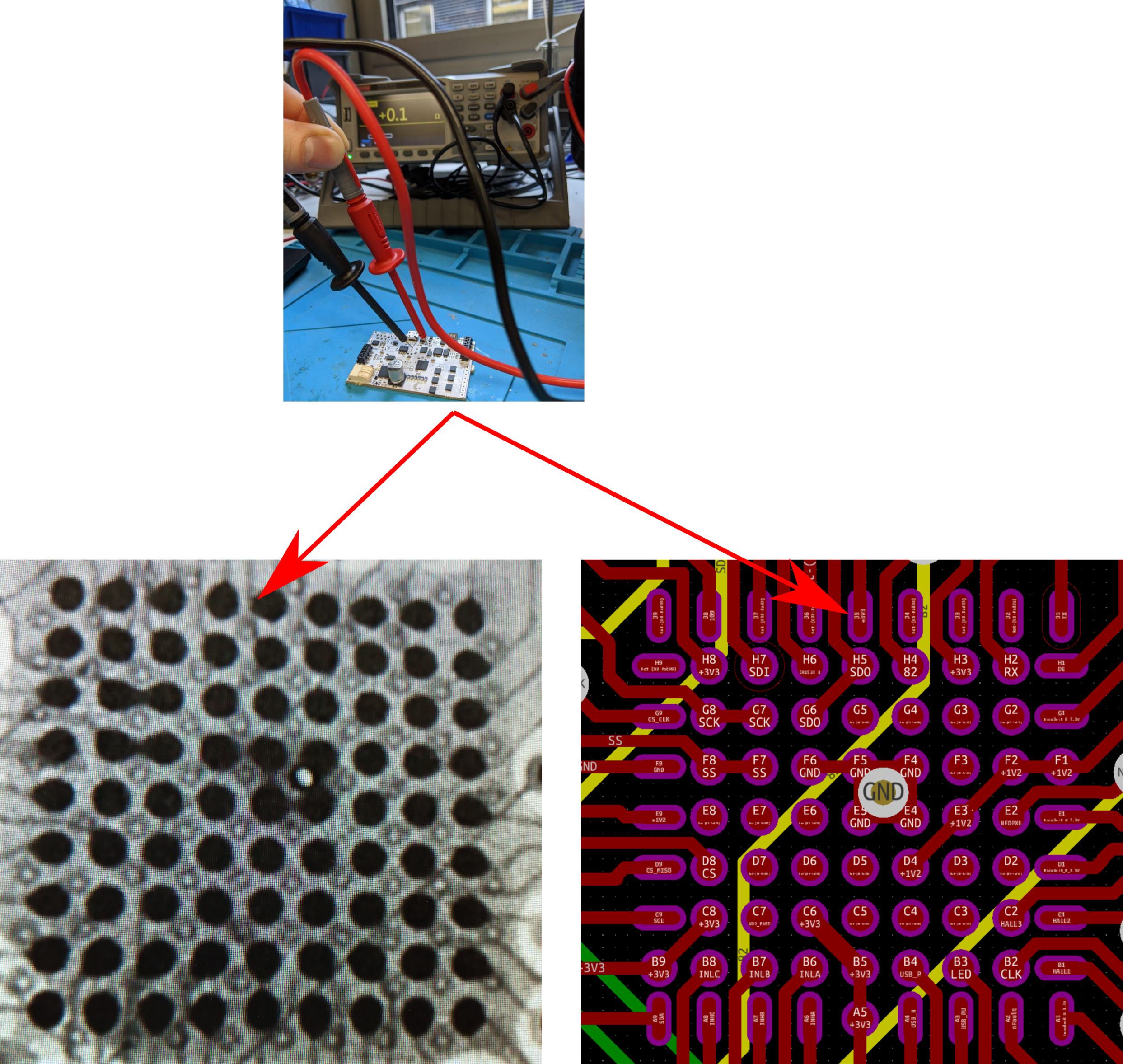
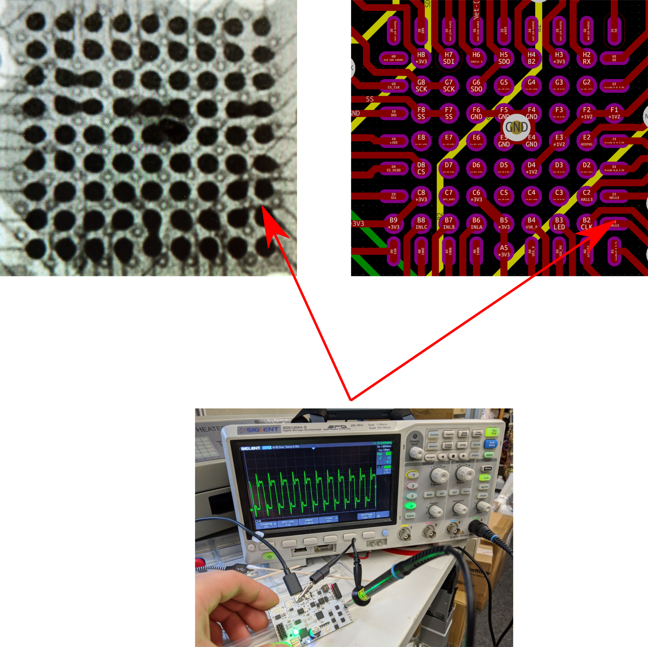
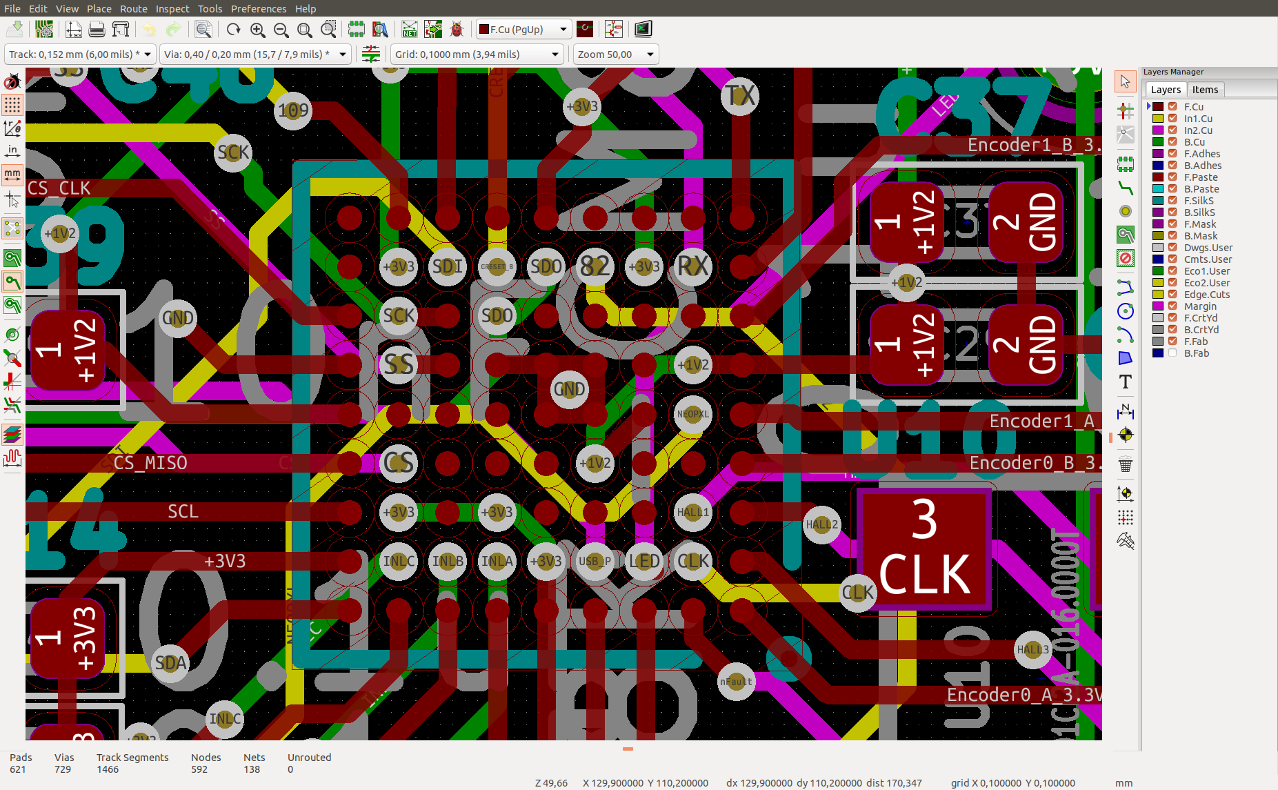
The x-rays unveil two of the most frequent defects. The first one is a short between SDO and 3.3V, which prevents the flash to be programmed. This was the case for over half of the boards. The second defect shows a short between the CLK and hall sensor pin. Both defects result from imprecise placement of the fpga too far left and too far up, respectively. So there is still hope for the bad batch to be fixed...let's see
UPDATE June 2020:
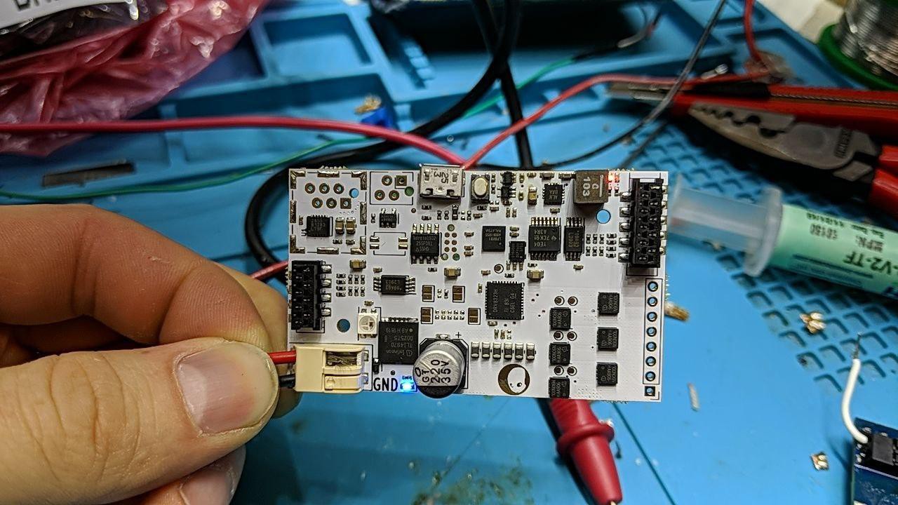
So as it turned out, there was a bug in my kicad design. Specifically when exporting to gerber, the default solder mask clearance caused the solder mask to be completely open for the ice40 fpga, which in turn made it close to impossible to solder it correctly without short-circuits. After months of debugging and discussing back and forth with pcbway, they finally agreed to redo the whole batch. The argument was that their pre-production checks should have spotted this bug. We had to pay for the manufacture of a new set of PCBs (around 600$), but they would harvest as many components as possible from the faulty boards. So finally they are in production and we can't wait to get them. In fact we inquired more manufacturers and this was very surprising to see, how expensive actually PCBway was. In Shenzhen there are literally hundreds of PCB manufacturers and it seems especially for PCB assembly it's really worth contacting as many of them as possible. We ordered a smaller batch of the v0.8 iceboards and they work out of the box. Here you can see the set to be used in roboy3:
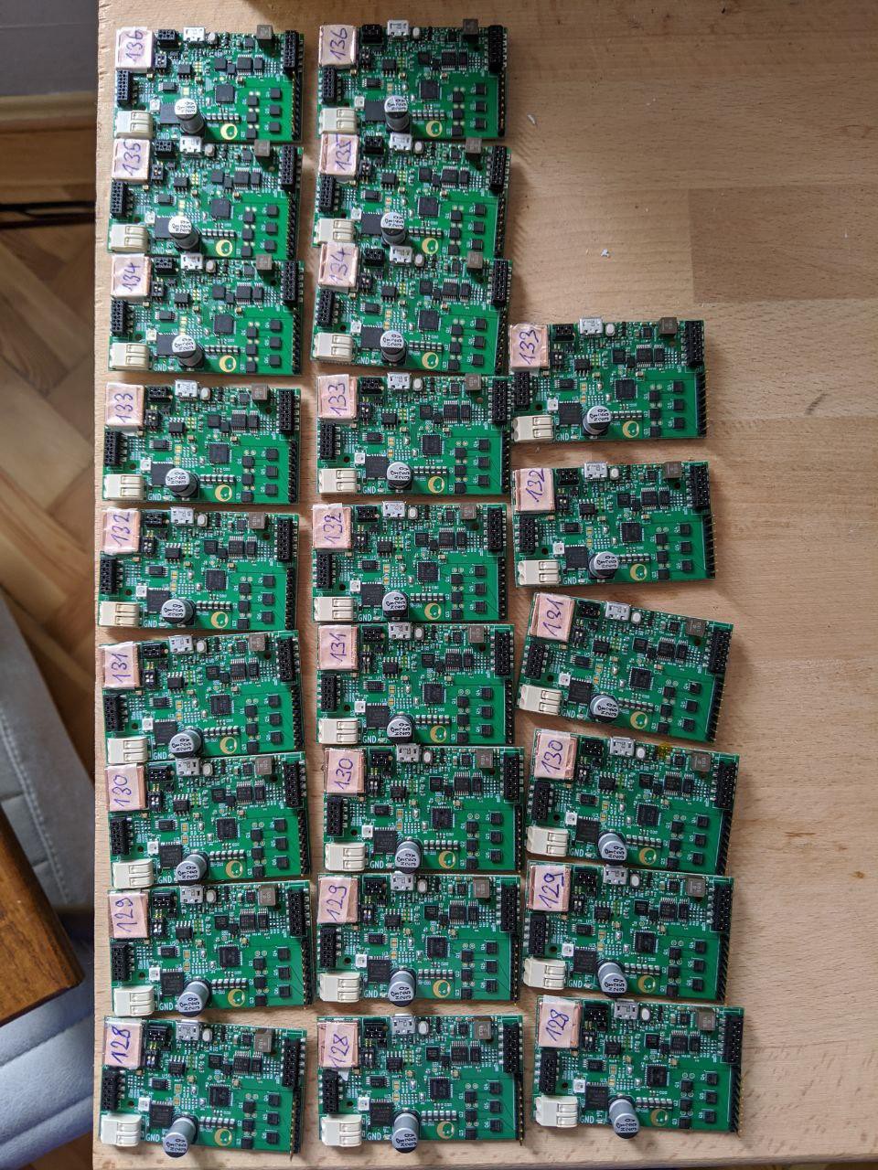
In this version I cleaned up the routing a lot, used the recommended footprint for the ice40 BGA and followed the routing design guide from lattice instead of blindly using the footprint that was used for the tinyfpga. The tinyfpga board used a footprint that was somewhat cheated into low-cost production. The footprint tries to use the outer perimeter pins of the fpga as much as possible. And the outer pads are elongated, to allow inner pads to be routed between them outwards. In this way, you can make a two-layer board, such as the tinyfpga, and route as many gpios as possible (i think it's 24 for the tinyfpga). However, if you need more pins, you should follow the design guide from lattice. They recommend four layers and blind vias. Blindvias especially can increase the PCB cost a lot, so I tried avoiding them. And as it turned out, it was possible to route all my pins using through-hole vias on our four-layer board.
Discussions
Become a Hackaday.io Member
Create an account to leave a comment. Already have an account? Log In.