 Petar Crnjak
Check out ourt official website: https://source-robotics.com/
Join forum: https://discourse.source-robotics.com
Join discord: https://discord.gg/prjUvjmGpZ
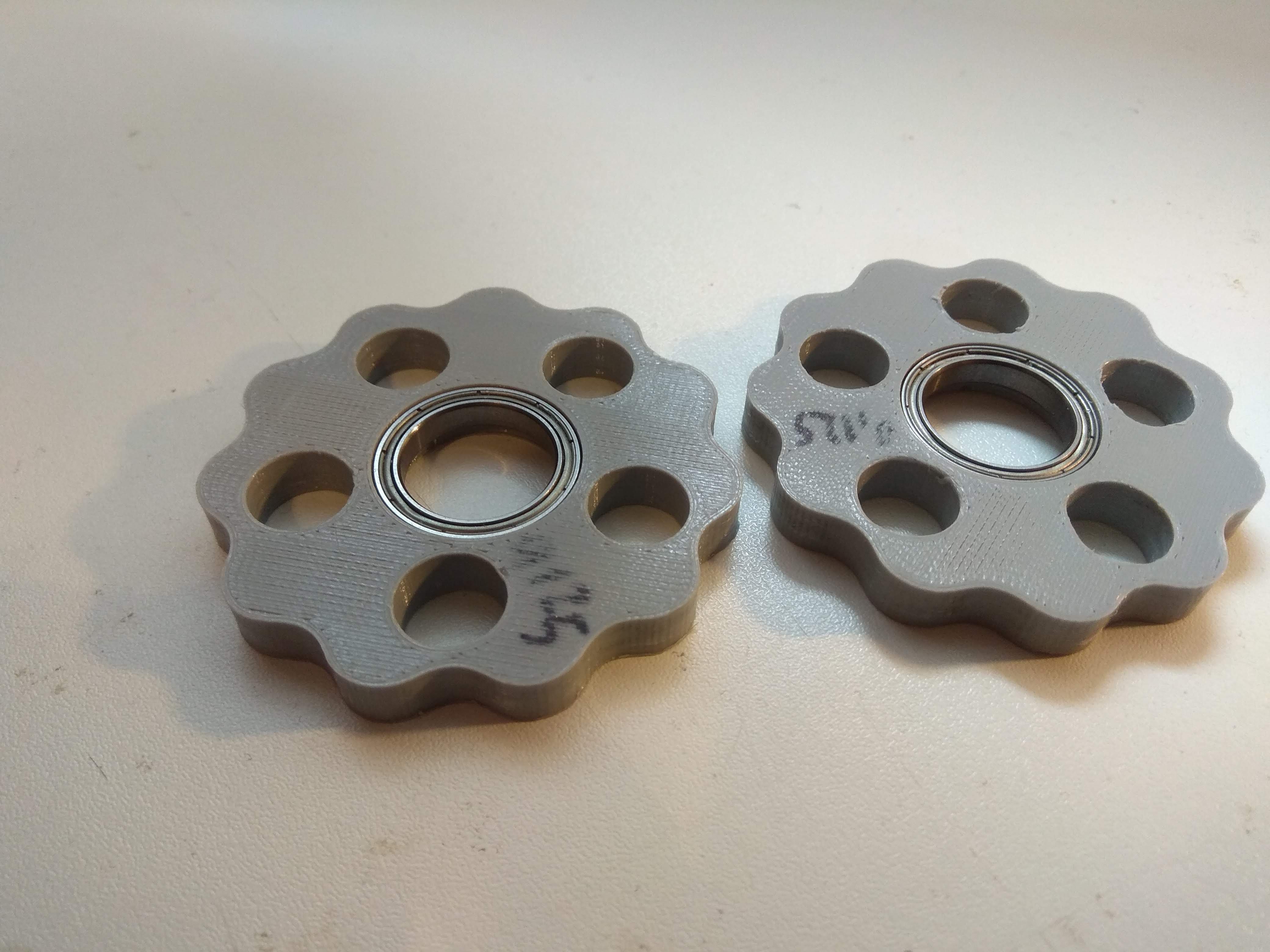
So the whole project started with cycloidal drives. Why cycloidal drives?
- They are really easy to 3d print
- can have large reduction ratio
- cheap
- low backlash even when 3d printed
When 3d printing them there are few things to keep in mind , but i might make video about that later.
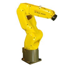
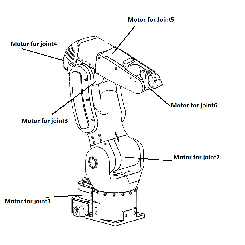
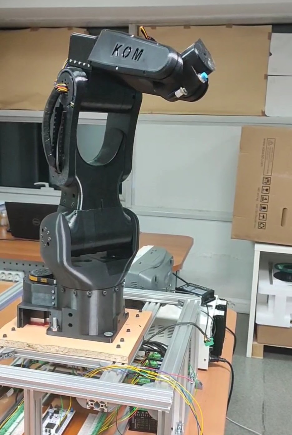
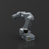
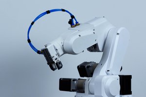
Design of the arm.
Esthetic design was inspired by FANUC’s LR Mate 200iD.
Goal was also to hide all wires in the arm like most industrial arms do. Only visible wires ( or pipes ) would be ones for gripper.
Weight of the arm is around 14-15 kg , but it can be reduced by printing with less infill.
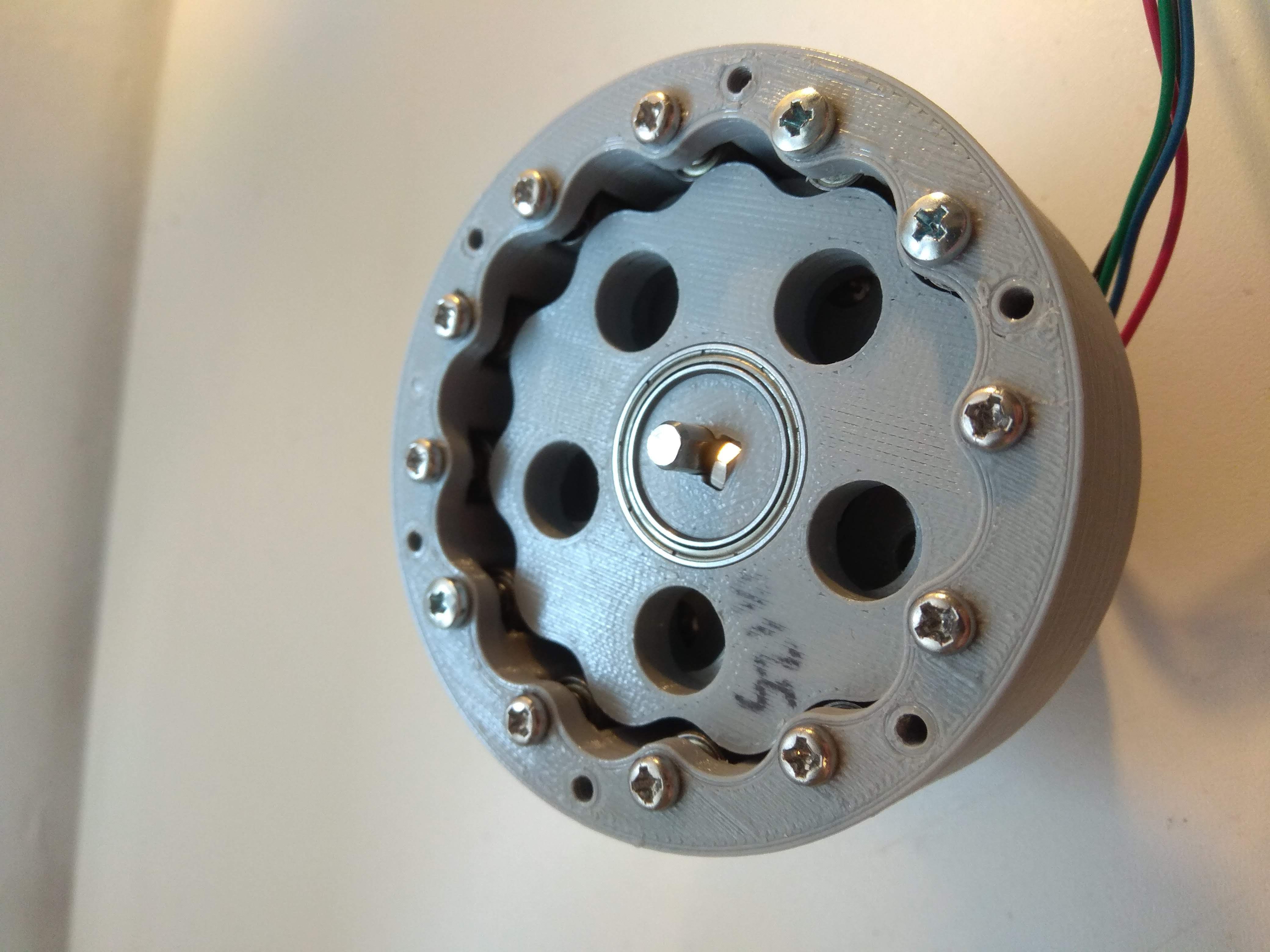
Motor position
Firstly i wanted to move all motors to the base of the arm to reduce weight each motor should carry. First idea was to just copy the design of this kuka arm. I decided against that design and just went with probably most basic design where every motor is directly on the joint of actuation ( Except for joint 5 that i moved a little bit away).
Joints 1,4 and 5 use belts in addition to cycloidal reducers. Belts are mostly used to offset the place where joint will be rotating so that we can route wires thru the body of robot. They also give some additional reduction ratio. For example Joint 1 has 15:1 cyclo but with belt our reduction ratio jumps to 25:1.


 Dimitris Xydas
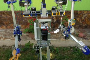
 Mihai Oltean
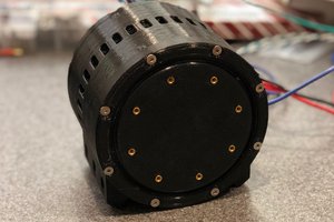
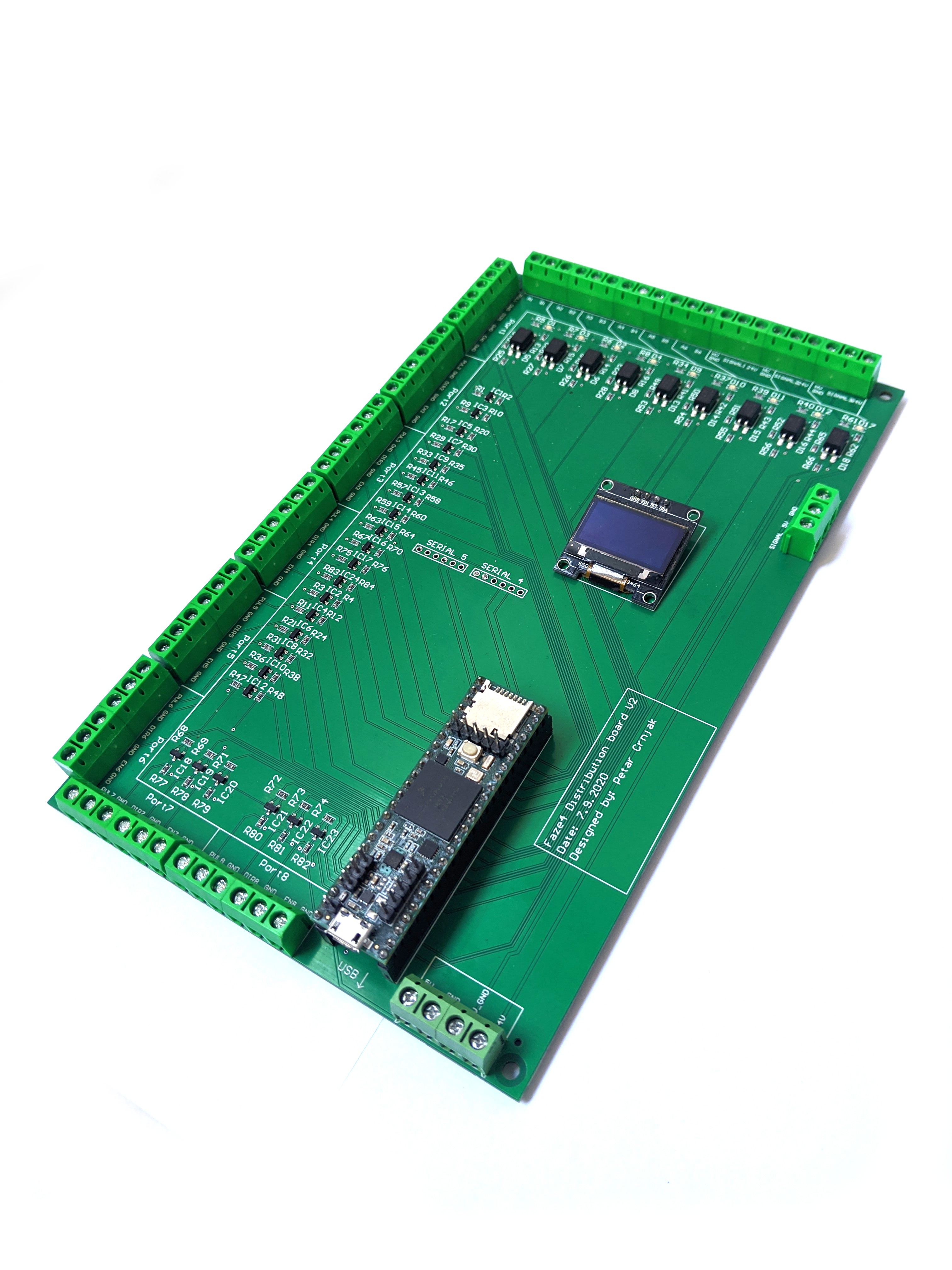
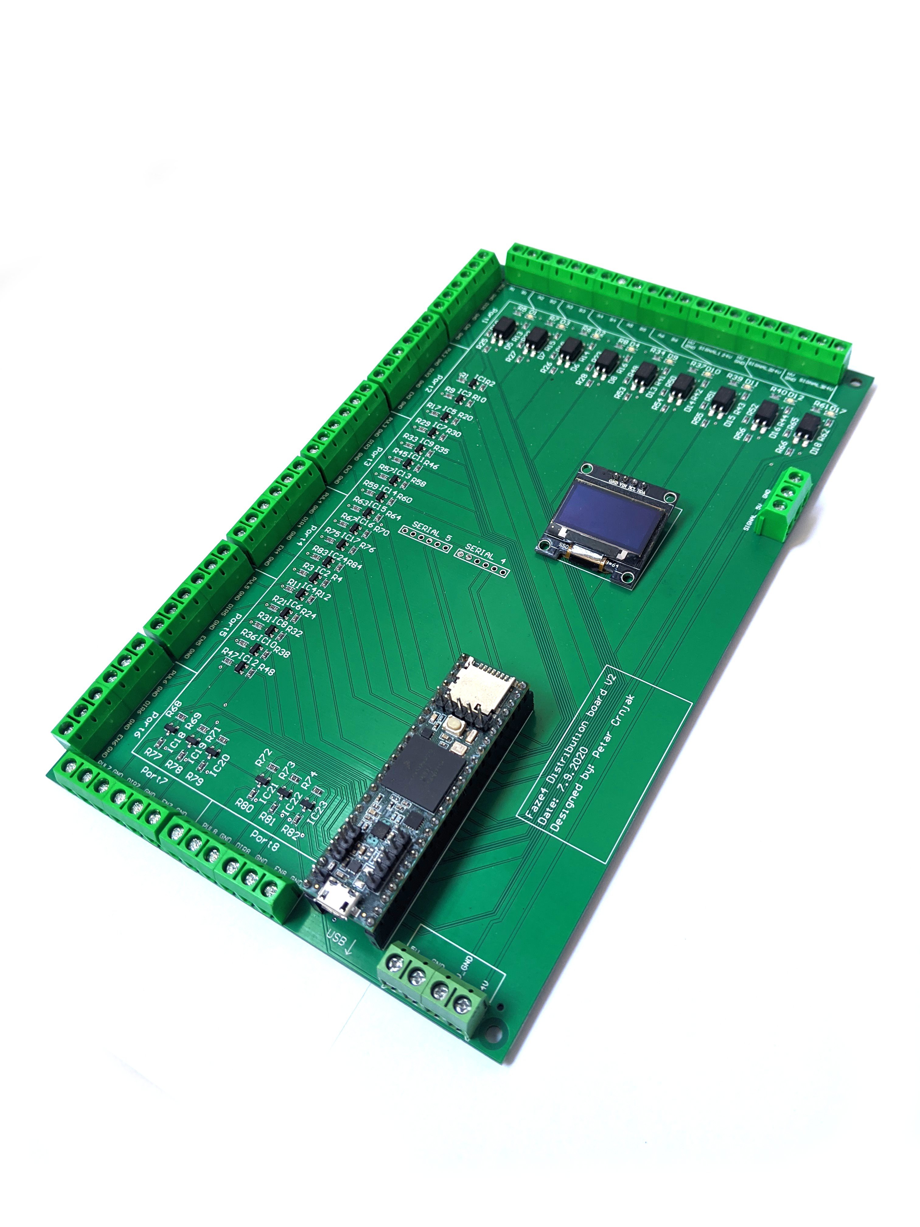
Can I still buy the controller board? I'm not able to buy it from the link provided. Please let me know specifically how I can obtain it. Thanks,
Luis