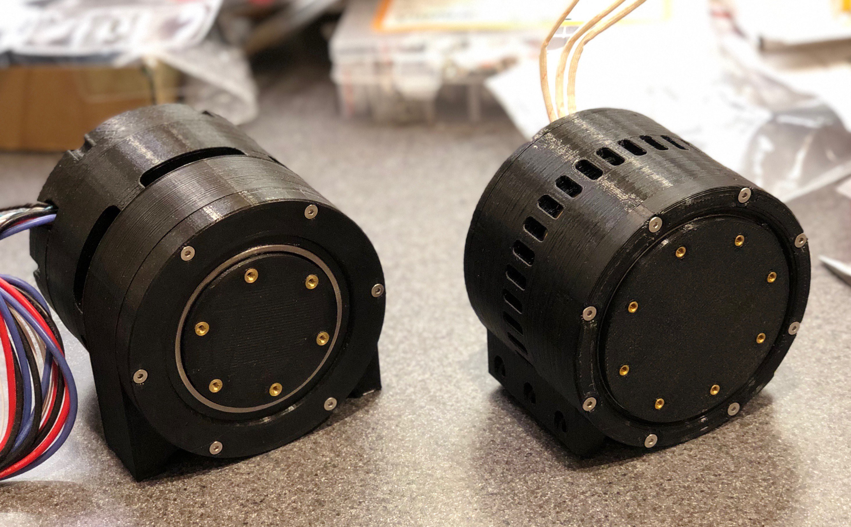
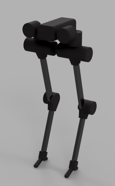
Specs:
- Peak torque (theoretical): 80 Nm
- Weight: 1150 g
- Gear ratio: 8:1
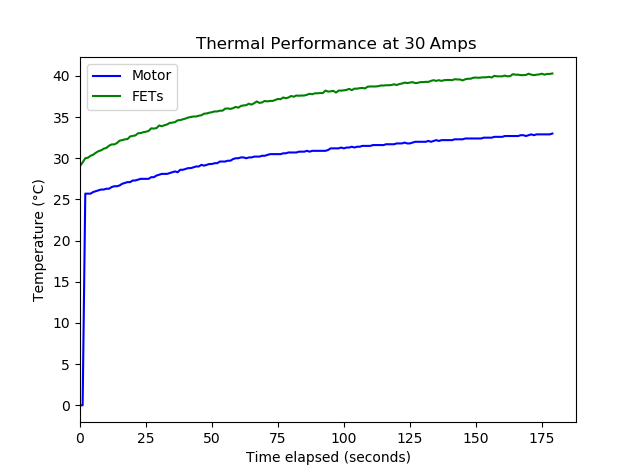
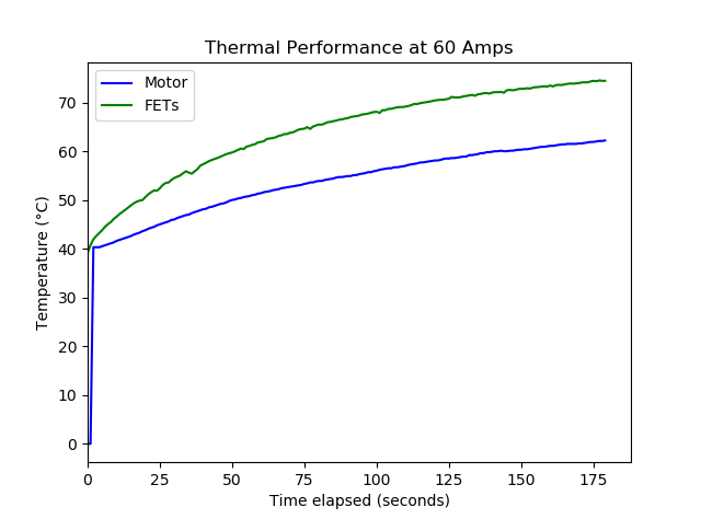
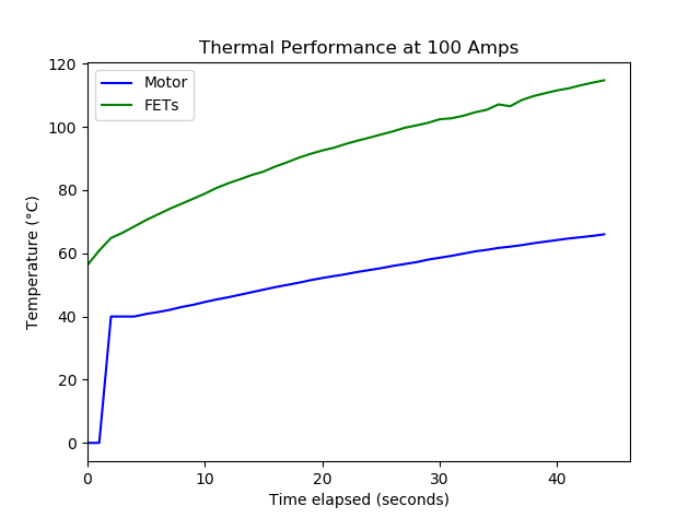
- Cooling: Passively cooled, active air-cooled version in the works
- Cost: ~$150
- License: Creative Commons Attribution - ShareAlike 4.0 International Public License
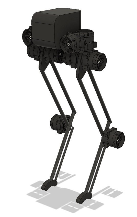
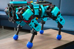
OpenTorque is being used in the Blackbird bipedal robot. Check that project page for links to the resources and inspirations I used when designing OpenTorque.
Get the latest CAD files and instructions from the GitHub repository:


 Petar Crnjak
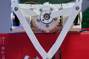
 Aaed Musa
Hello Gabrael, your project is really very interesting.
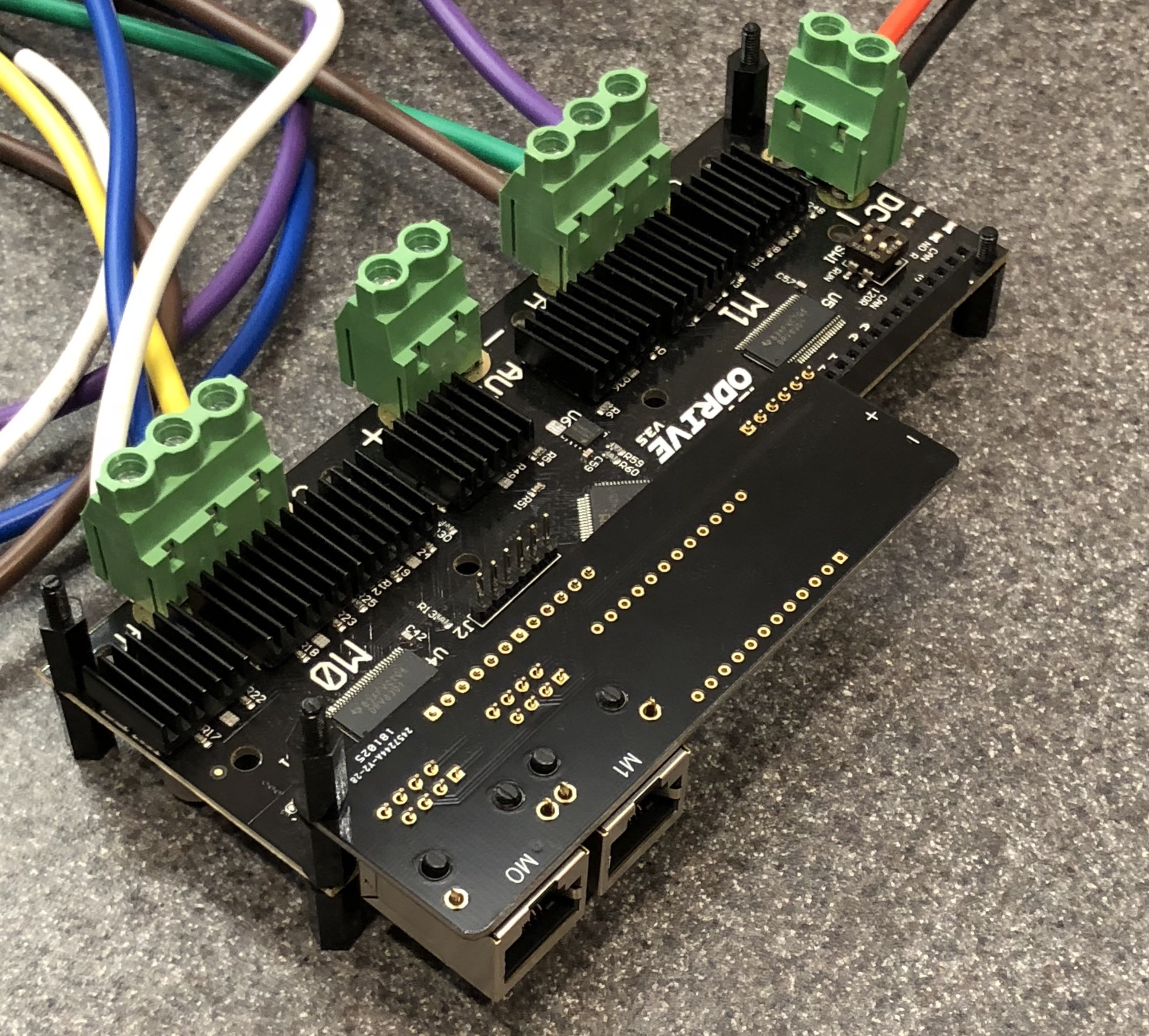
I am currently developing a project with a BLDC motor, and with an Odrive v3.5 controller, which I need to control the torque of the motor. To do some initial tests and get to know the Odrive controller, how can I program it to handle the torque control?
Thank you very much Gabrael and Congratulations!