A little bit of history
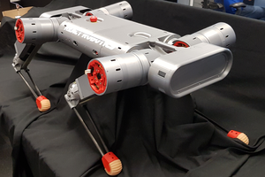
The design I'm presenting is a result of multiple iterations that I've either designed or designed and built in a period of ca. 2 years. I started with an idea of building the smallest possible 4 legged robot driven by brushless motors. The design I came up with for a leg was a deltoid linkage. After a little bit of googling I found Ghost Minitaur robot which used exact design for legs. That convinced me it was a reasonable choice.
First motors I used were 34mm dia. motors, used for gimbal stabilizers, which I found on eBay. I built a small prototype leg, and while it worked, it didn't really provide much torque. I could build a very small scale robot around them, but fitting of-the-shelf electronics, battery, bearings etc. on such a small robot would be beyond my skills.
That's when I found a wholesale of 5222 gimbal brushless motors on eBay. I risked and ordered 12 of them. I only paid less than $100 for all 12 of them, which I think was a great deal. After a bit of testing they turned out to have 2.8kg/cm torque @24V, which should be enough.
And while at it, I decided that 2DoF per leg is quite limiting and not challenging enough for a hobby project :) That's where the current design started.
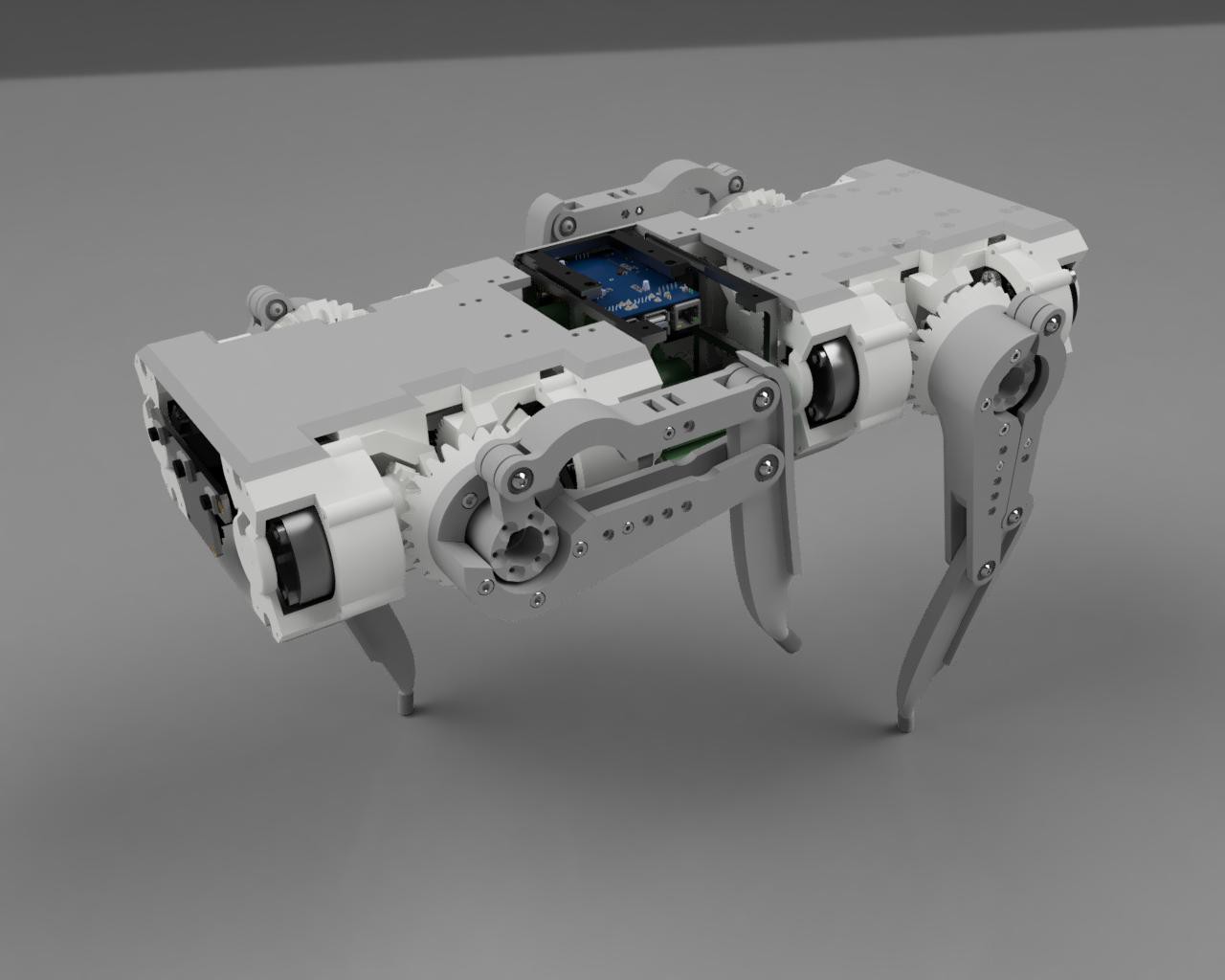
Mechanics
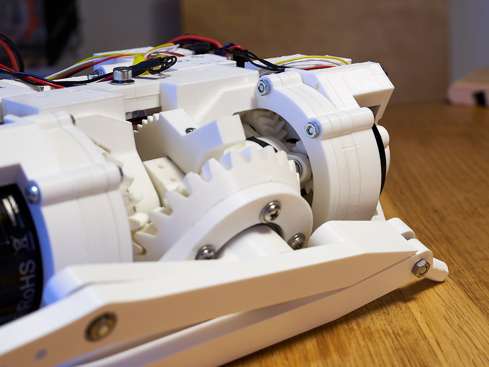
All structural parts and also gears are 3d printed in PLA. It took a long time and fiddling to get this right, but I'm very happy with final quality of gears. I printed them with 0.1mm layer height to achieve the smoothest surface possible. Some of them required a bit of polishing, others were good to use straight from printer bed.
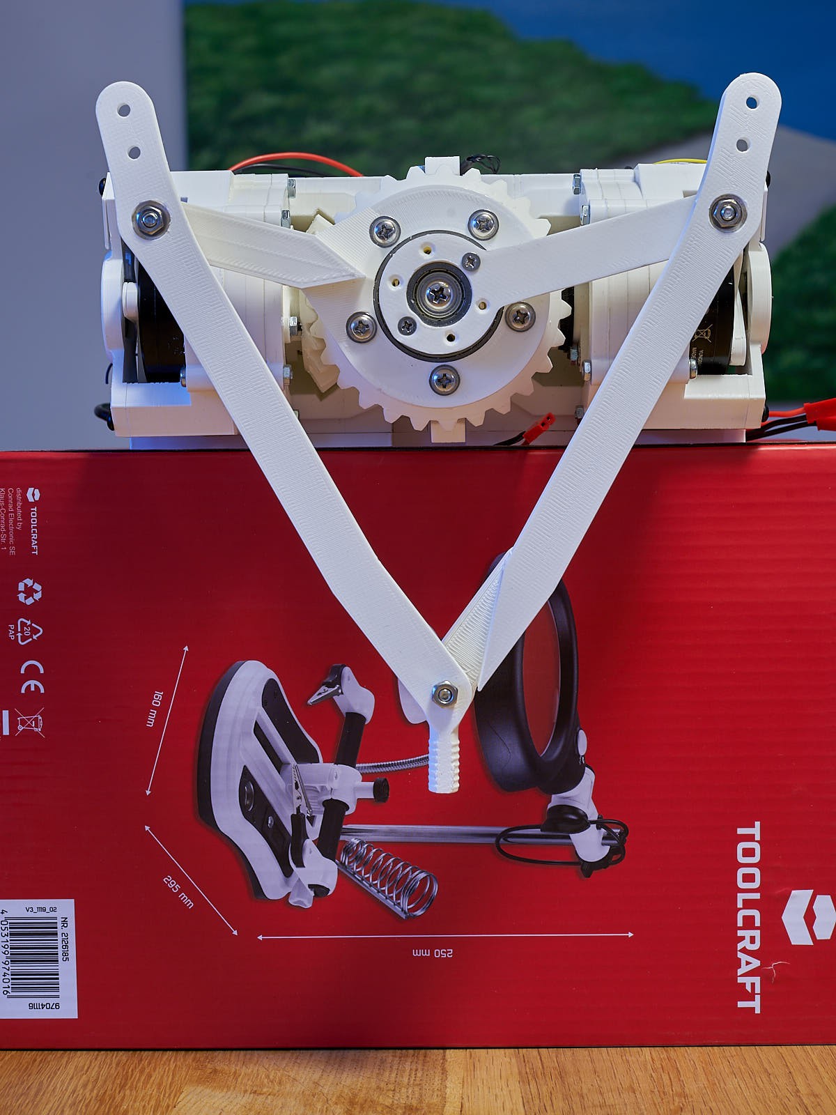
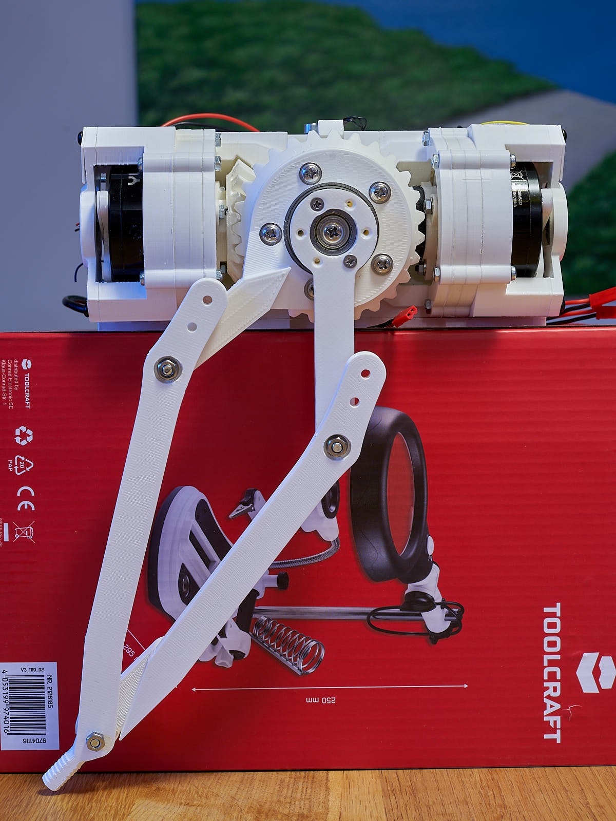
I'm particularly proud with the joint design. It is a 3DoF joint, were all the motors are stationary. This should provide low inertia for the leg - something that's very much desirable.
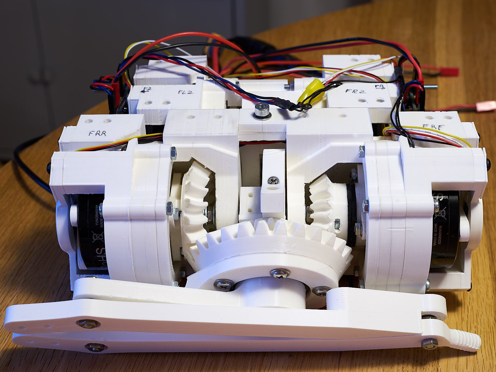
The main principle is that the two bars of a leg are driven by coaxial shafts, which are driven by a pair of bevel gears. Second gear of each pair is coaxial with axis of the side swing motion. And the swing is powered by a third motor that is closer to the center of the robot.
Rotation to each bevel gears and the twist gear is transmitted through a planetary gears with 1:4 reduction. There's extra 1:1.5 reduction on bevel pair and 1:2 on the swing gear giving total of 1:6 reduction for two 'main' axes and 1:8 total reduction for swing axis.
Here's how the leg will function.
Electronics
Powering brushless motors requires programmable, brushless electronic controllers. These are quite available as controllers for gimbal controllers on flying drones. However, it wasn't easy to find cheap ones that can handle quite large currents that these motors need. Except the one from RCTimer. In fact, I managed to buy 7 of them for $5 each, on sale! These use L6234D chip, which should be just right for these motors. They also have voltage controller which can support 24V. Each of these controllers support 2 motors, so I need 6 of them and I have one extra in case of magic smoke :)
To implement position control with brushless motors there have to be some encoders coupled with them. I used the cheapest AS5600 modules I could find on AliExpress. The problem with AS5600 is that they have a fixed I2C address which can't be changed in any way. And I need to handle 2 of them for each controller - since each has 2 motors connected. Luckily I found a simple solution here. This required only 2 resistors, 2 diodes and a minimal amount of soldering. Success!
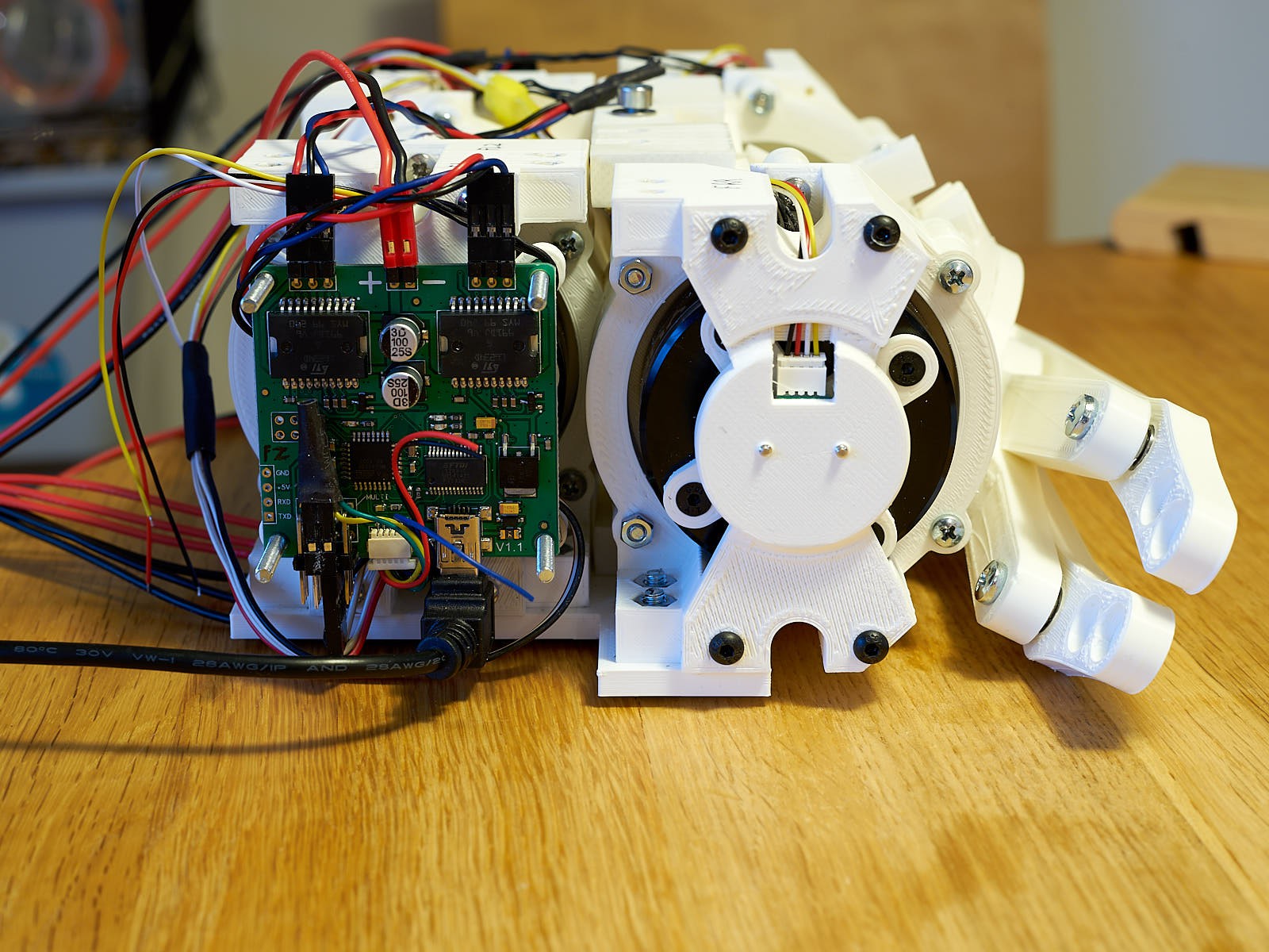
There is ATmega328p on these boards. I wrote a custom firmware for them which is driven directly from my PC at the moment, but eventually will be controlled by a microcontroller like Jetson Nano or Odroid C4 - I haven't decided yet which one to choose.
Software
Coming soon!

 Charles Galambos
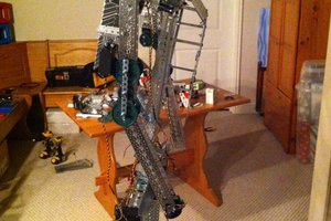
 Anthrobotics
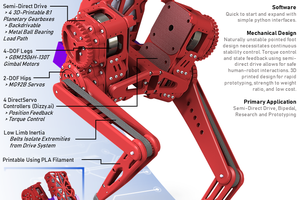
 Darren V Levine
 Aaed Musa
but position control will probably be not enough, the key to the cool walking robots is torque control wich acts as spring damper..