 Kyle Isom
I've long wanted to build my own laptop. I have a project to create a custom laptop, which is currently stalled due to trying to figure out some hardware questions. However, I was recently watching Halt and Catch Fire, and it really just made me want to build my own 8-bit computer and write some assembly. My first thought was doing something with the 6502s I have sitting at home, but as I poked around, I figured I'd start with the Z80. The experience building this will definitely be useful later on.
A while ago I built part of a CPU from transistors, but that became tedious, so I decided to build them out of 7400s. The upside is now I have a ton of 7400s (and others in the series), and there's this awesome company called OSHPark that manufactures perfect purple PCBs for you. I guess the question is, why not build a computer?
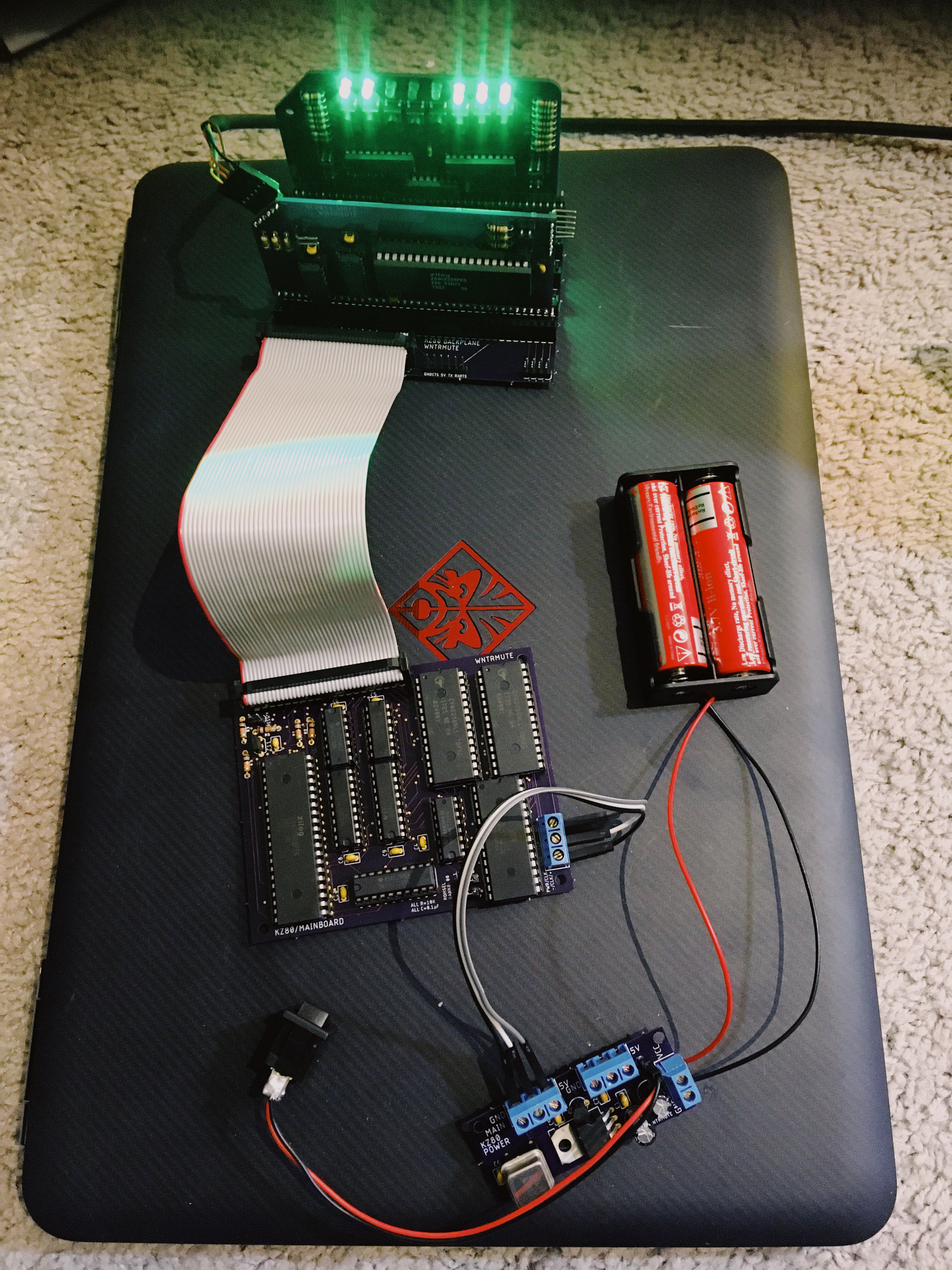
Tbe goal for this project is to build a computer that I can completely understand with hardware that's easily replaceable. As such, the logic boards will have all through-hole components and use IC sockets for all logic chips.
Eventually, I'd like it to be solar charged with both WiFi and LoRa modems; the first step is getting a working basic machine first.


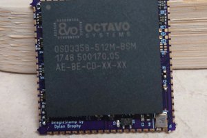
 Dylan Brophy
 John Adams
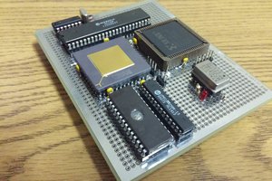
 Jason Westervelt
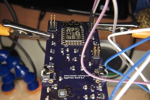
 Casual Cyborg
very nice