0%
0%
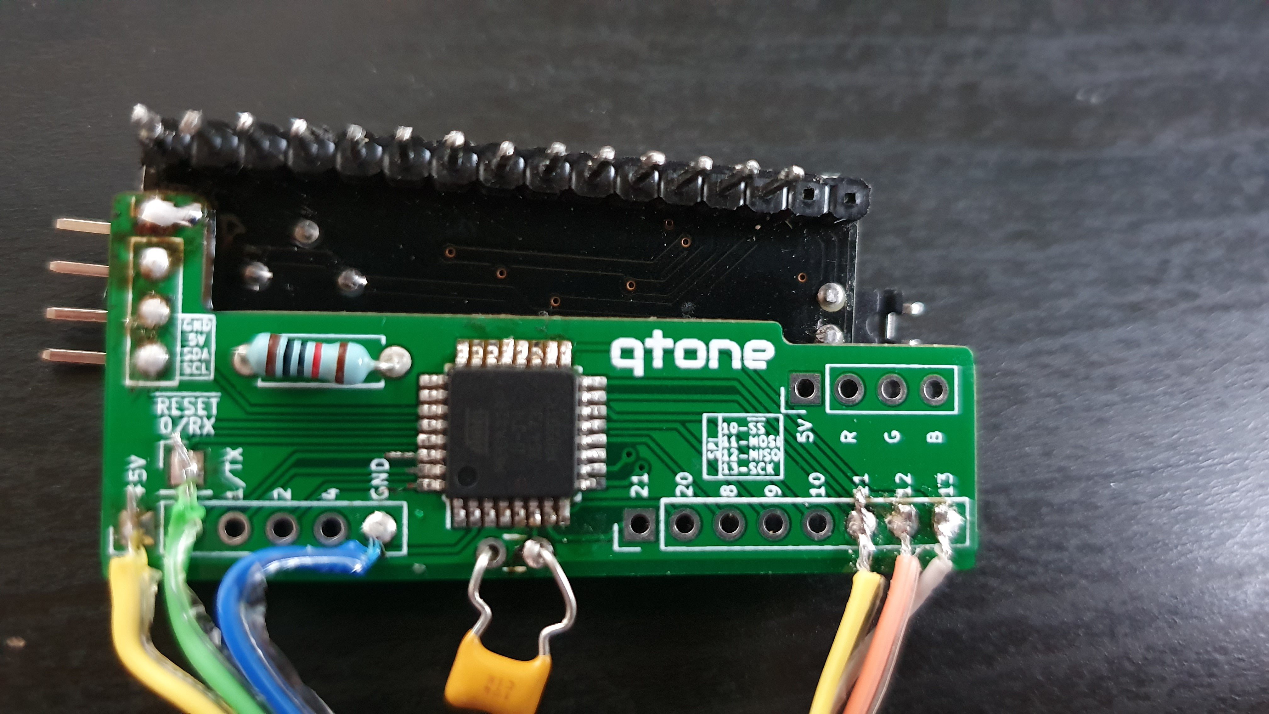
RGB LCD Backpack Addon
Additional IIC backpack for the IIC LCD backpack
 smartroad
Become a Hackaday.io member
Already have an account? Log in.
Just one more thing
To make the experience fit your profile, pick a username and tell us what interests you.
Pick an awesome username
hackaday.io/
Your profile's URL: hackaday.io/username. Max 25 alphanumeric characters.
Pick a few interests
Projects that share your interests
People that share your interests

 Here is a quick video of my test unit randomly selecting palette colours:
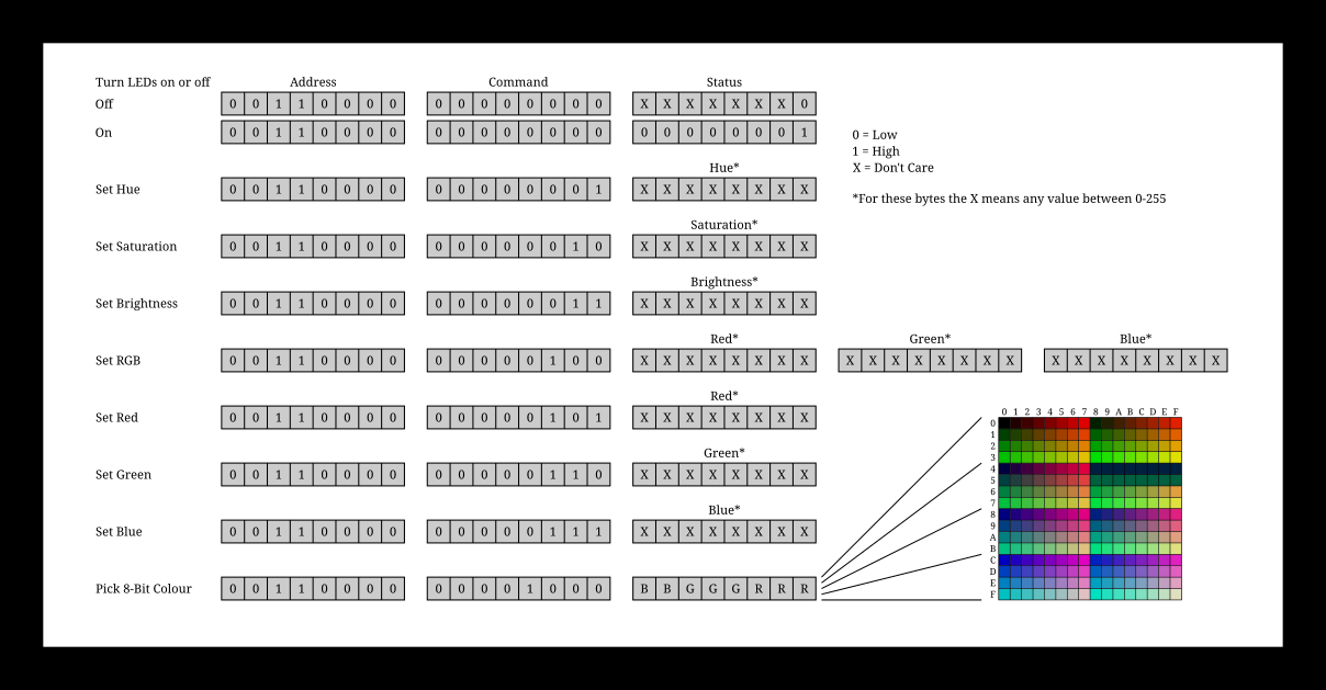
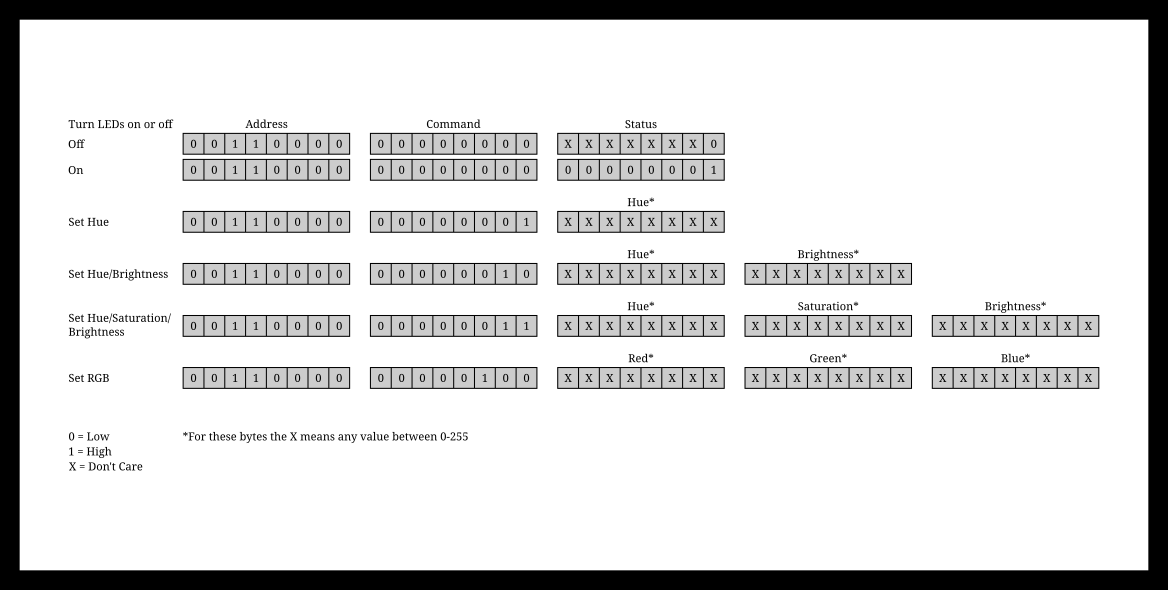 As indicated when setting hue, saturation, brightness, red, green or blue values they can be anything in the range of 0-255, allowing a full 16 million colour palette.
 Jeremy g.
 teardownit
 PK
PK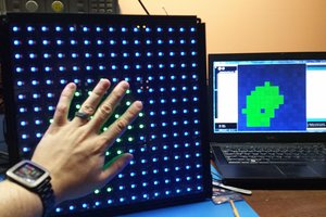
 engunneer