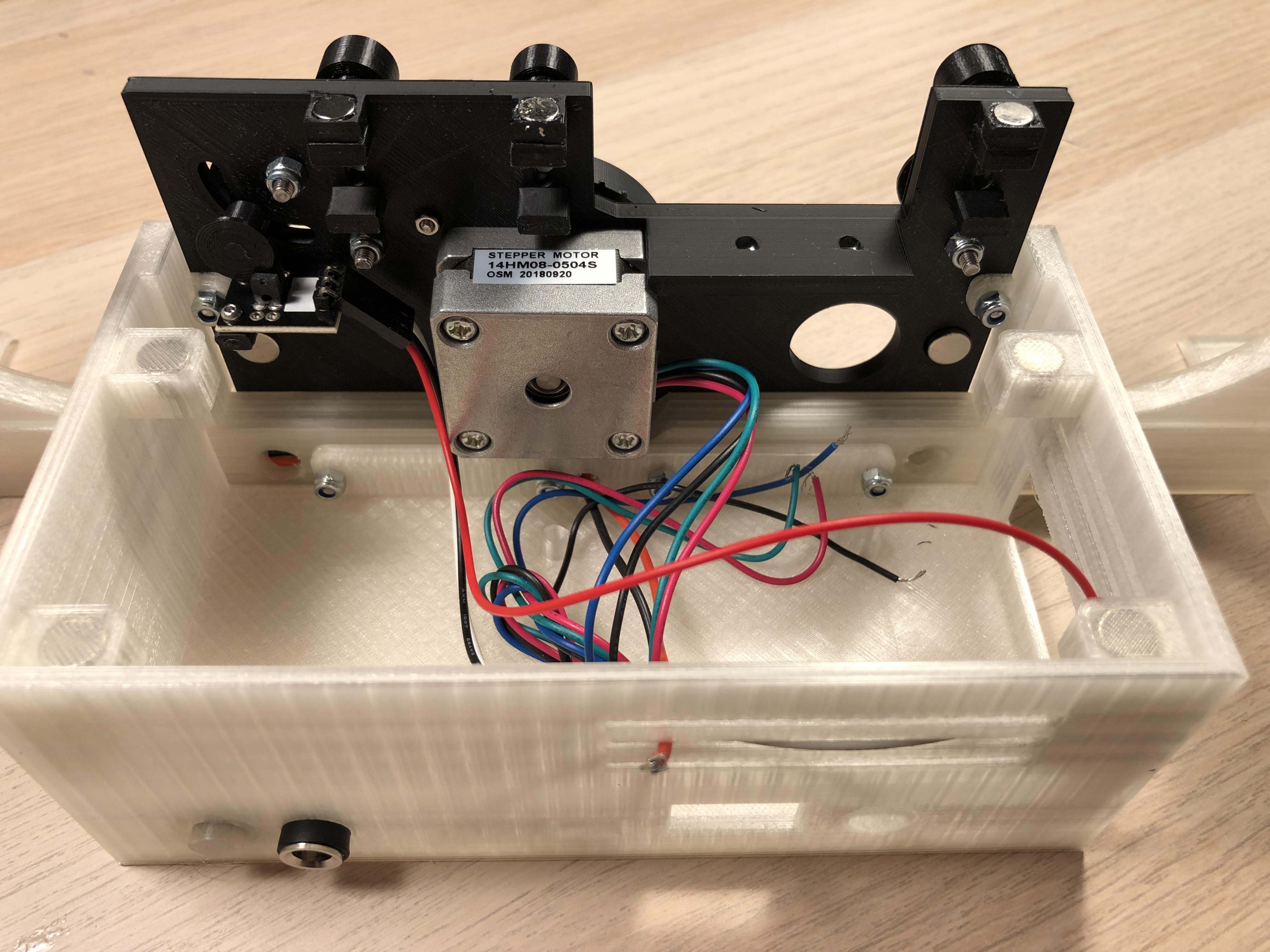
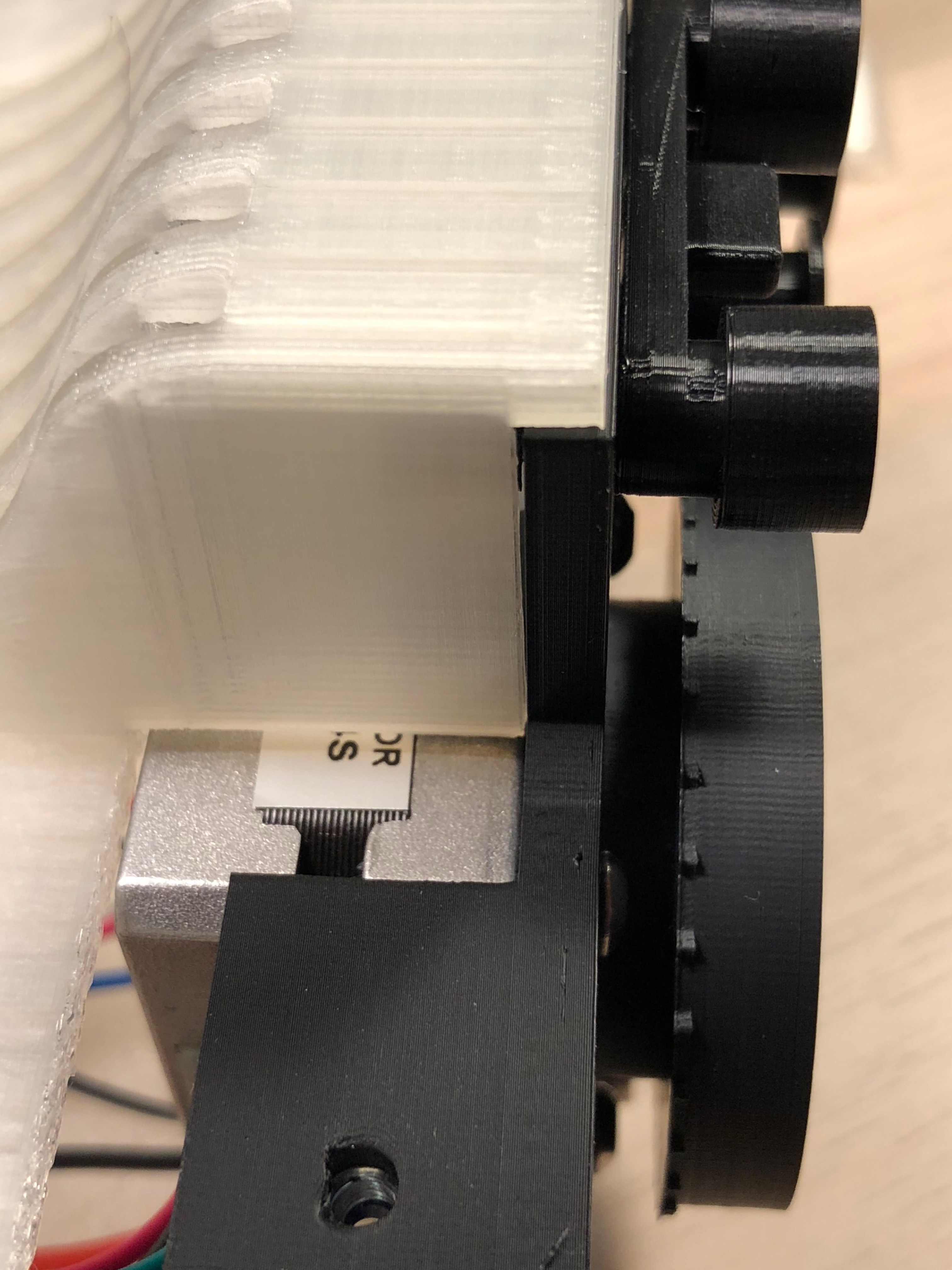
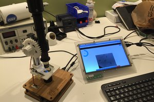
Close
0%
0%

8mm Film Scanner

Scan regular 8 and super 8 film and create a digital copy

Similar projects worth following
When a relative of mine passed, she left behind a lot of 8mm film reels. I figured too many to bring to a copy shop to digitise them. I searched the internet and found several solutions - from ready to use copy machines to dyi projects. However, non of them fulfilled my requirements, but my curiosity was sparked and I thought of making one by myself.
I went already through some iterations of designs to create a reliable, easy to use 8mm film copy machine.
I learned a lot along the process: about the raspberry camera, fusion 360 as a tool to design the parts, easyeda to design a pcb and OpenCV to analyze the pictures taken. All this things where a first for me - and I'm still learning :)

The basic idea is to move the 8mm film frame by frame with a stepper motor and take a picture of it. Afterwards putting the images together to a film.

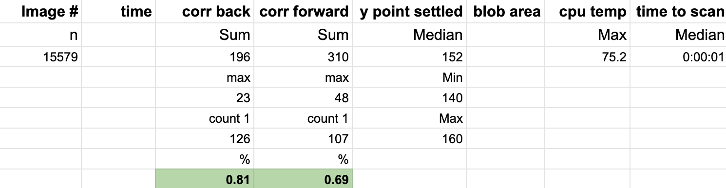
The frames are quite small (abt 5x4mm) and in order to have a smooth playback of the film, the positioning and cropping of the images is critical. 

After initial tests, I decided to use OpenCV for positioning and cropping. 

First comparisons between a "professional copy" and the built here looks promising, but I believe that especially the camera settings still can be improved a lot.

Here a short video made with the scanner: (original from 1976)
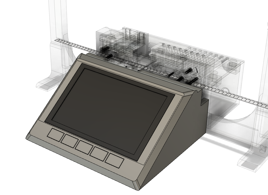
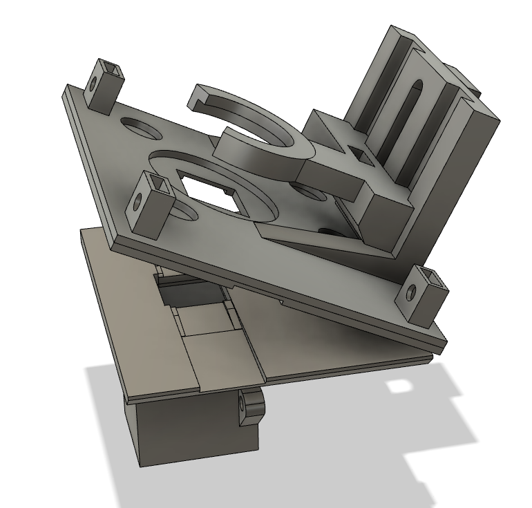
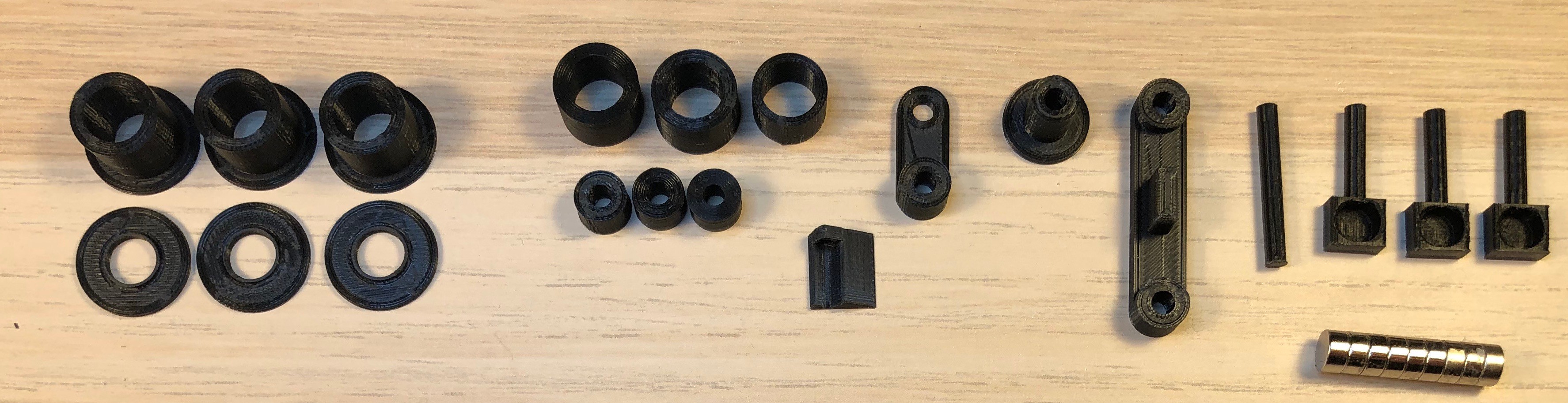
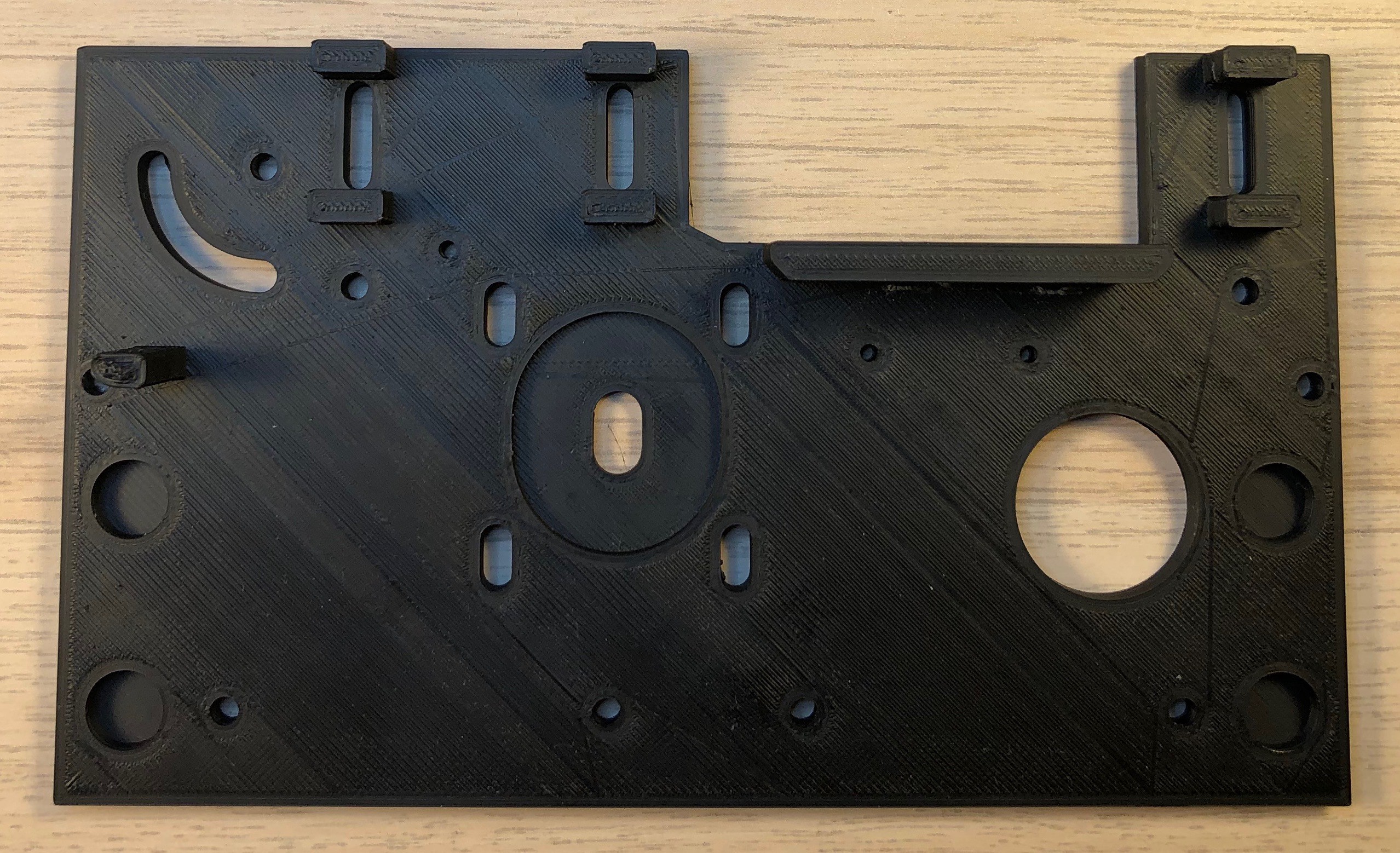
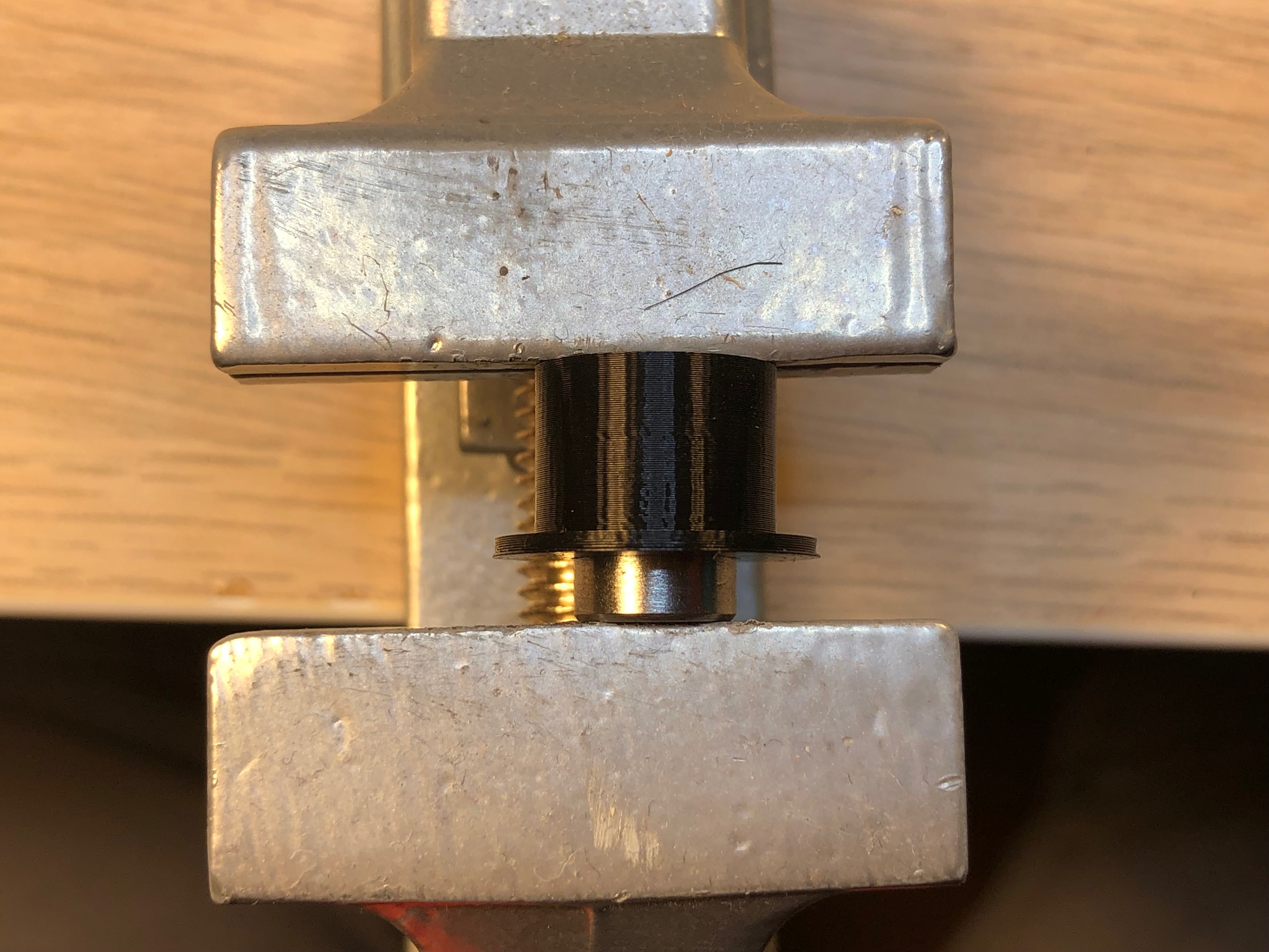
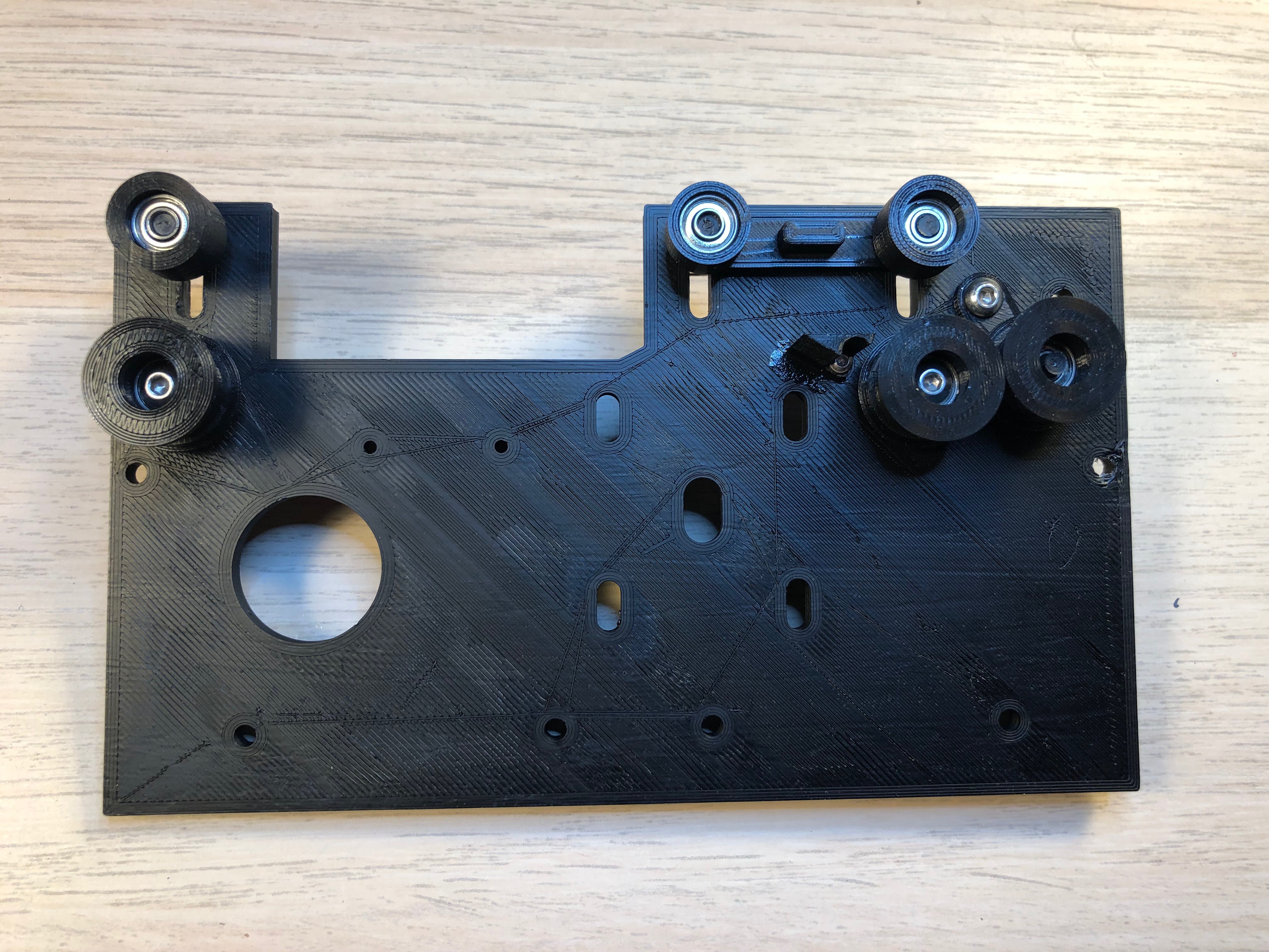
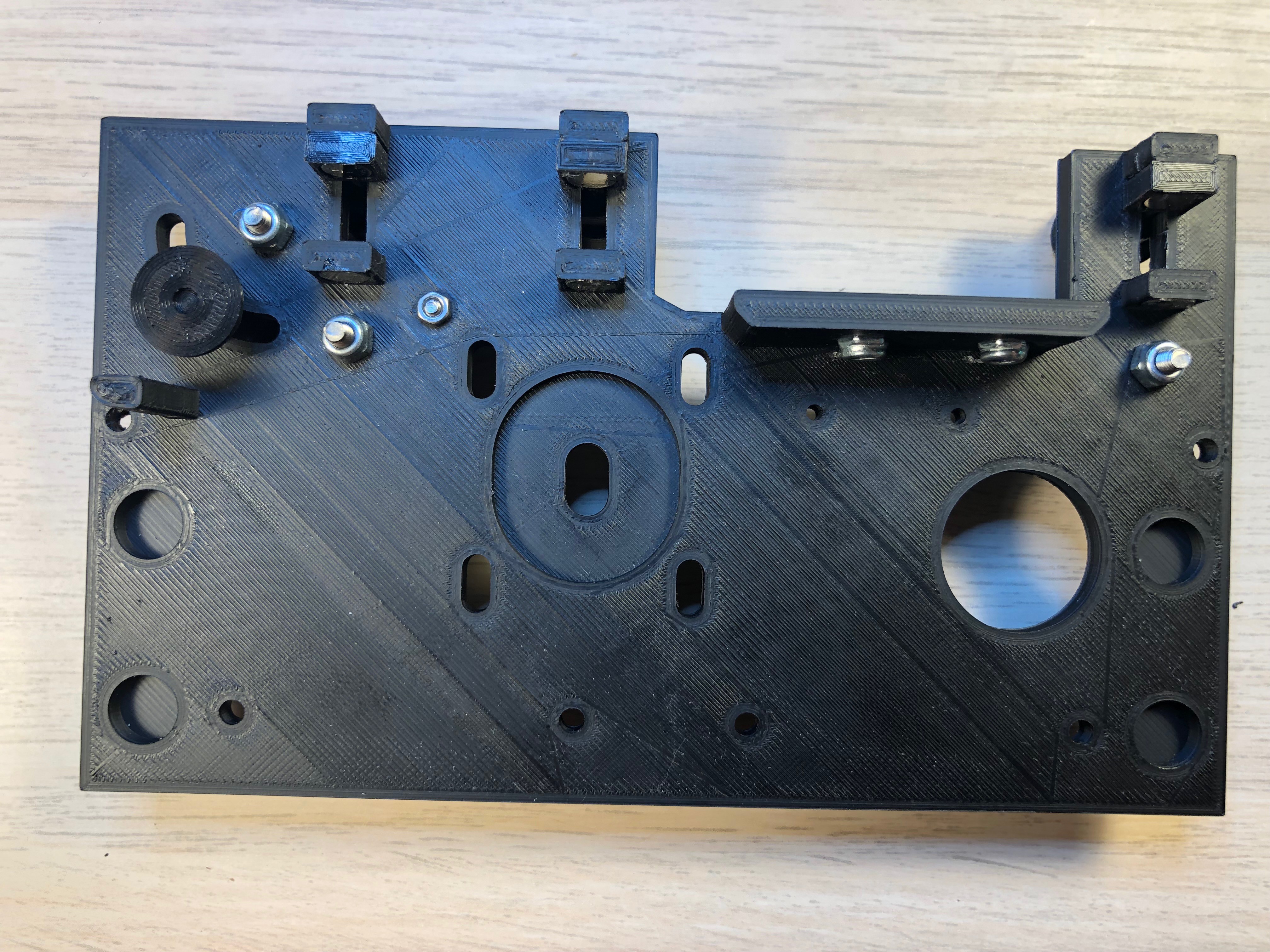
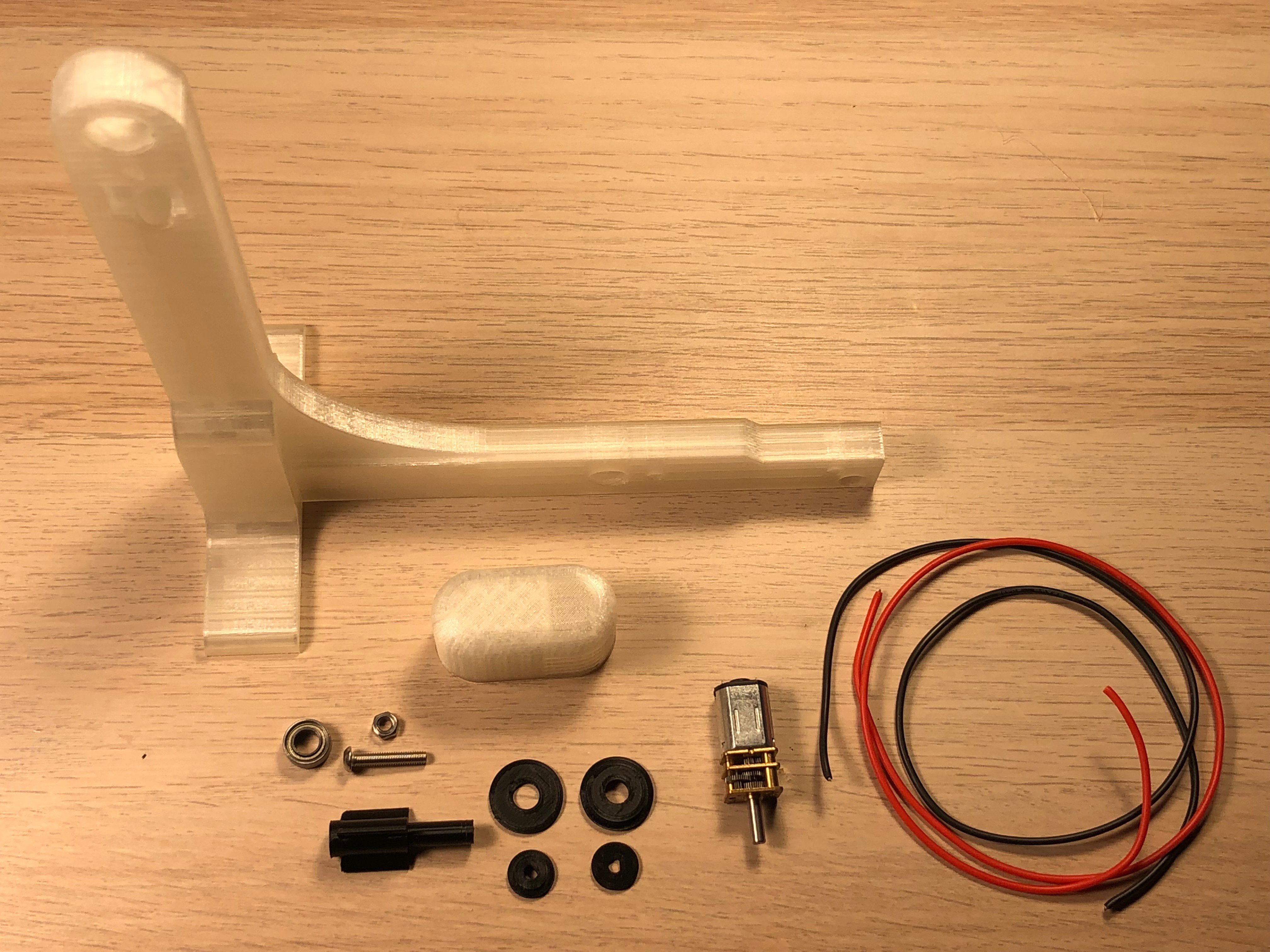
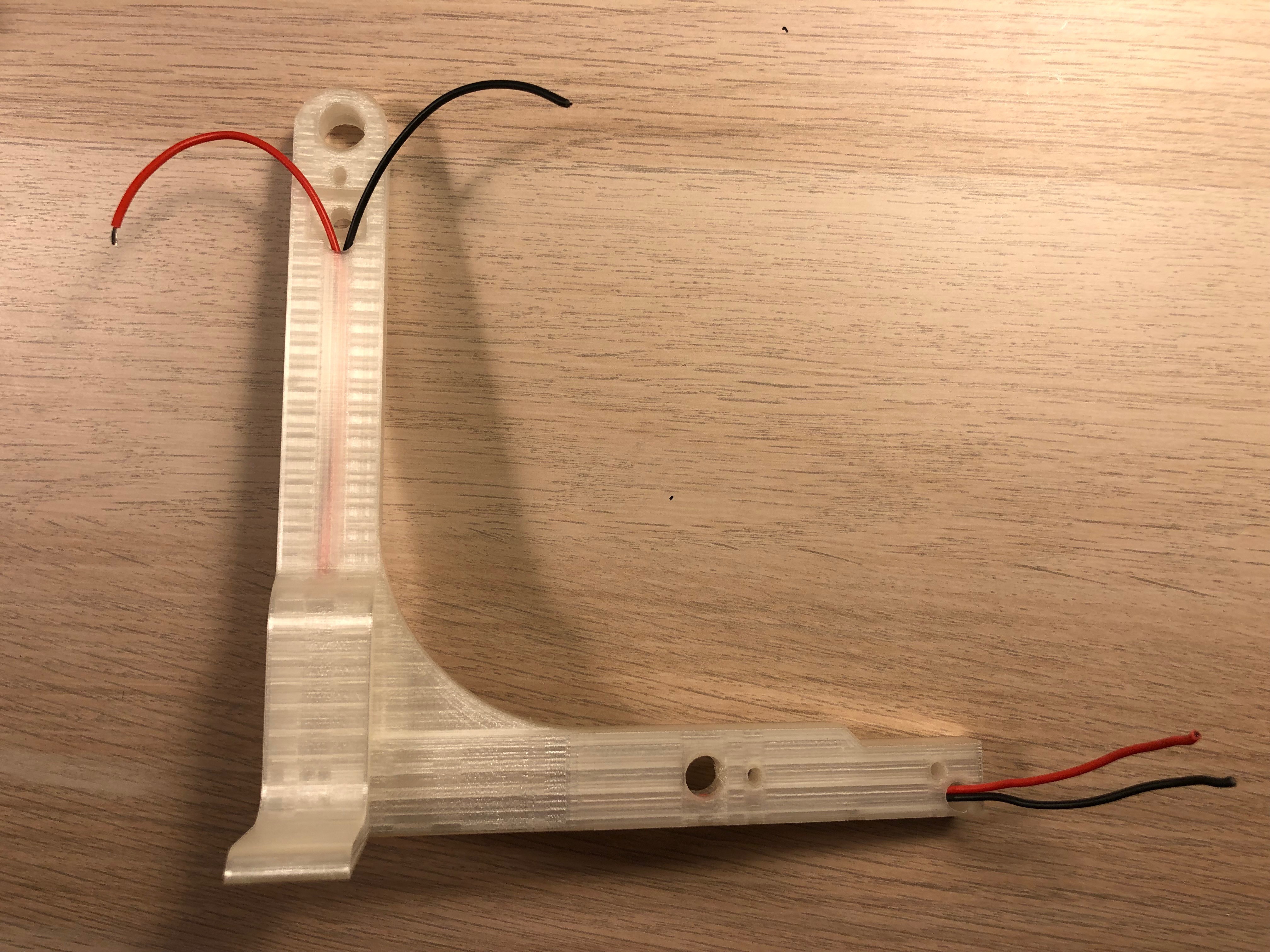
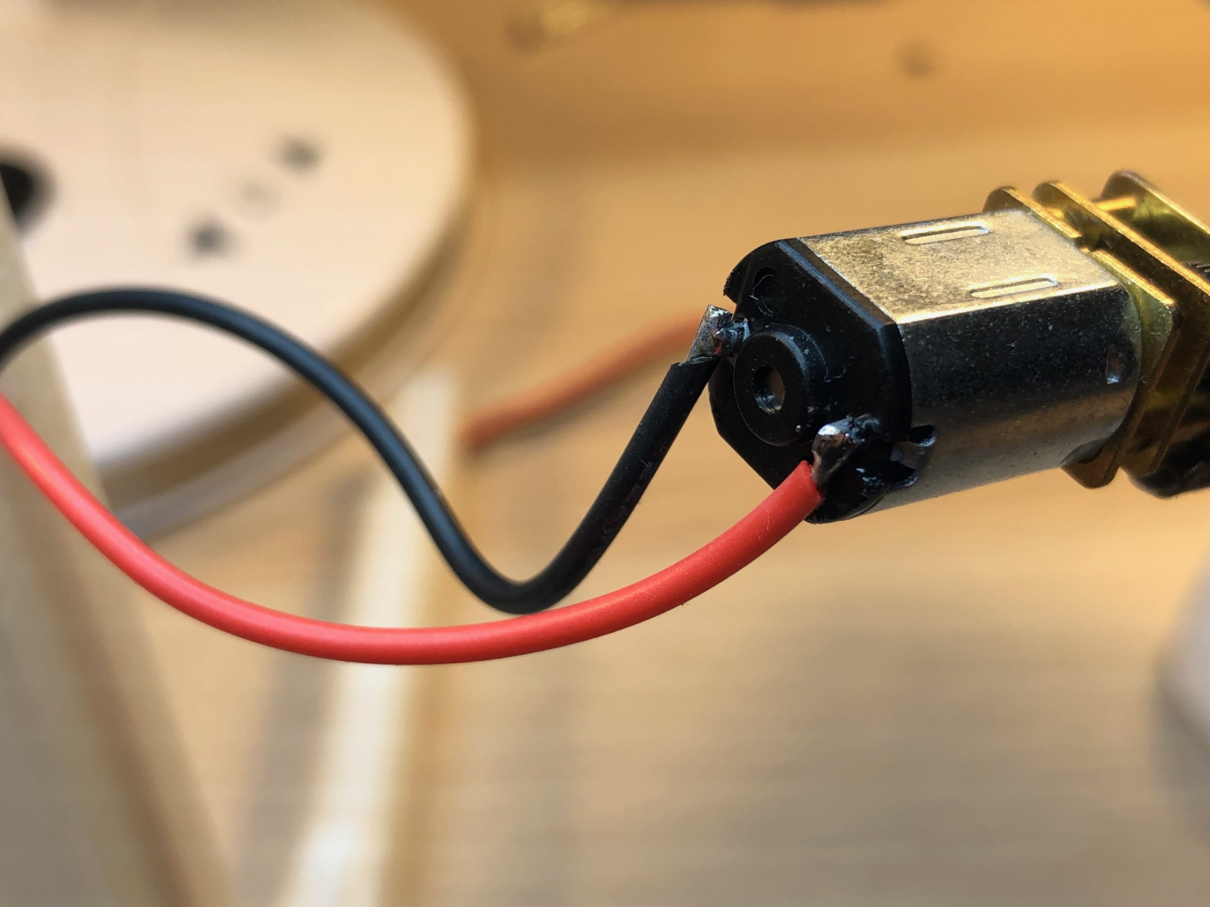
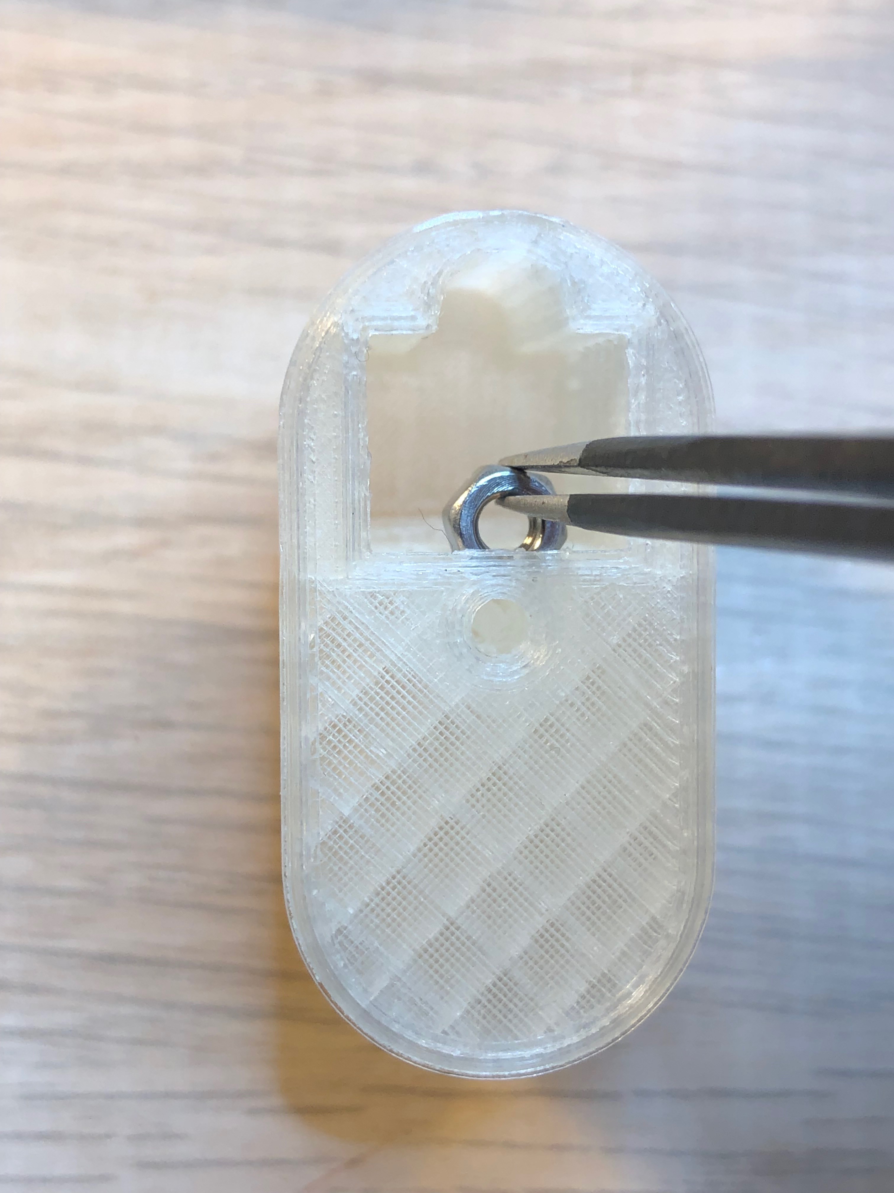
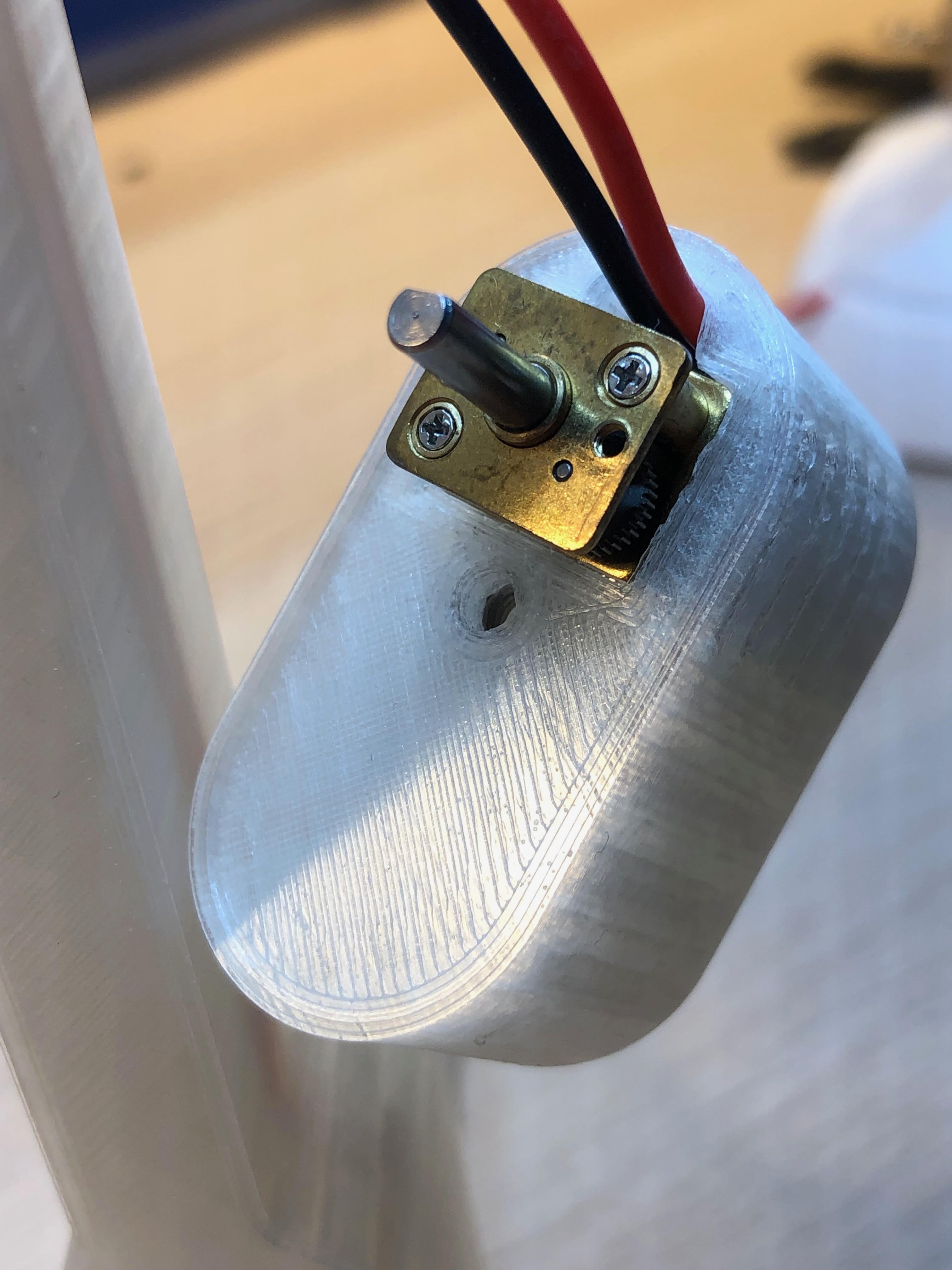
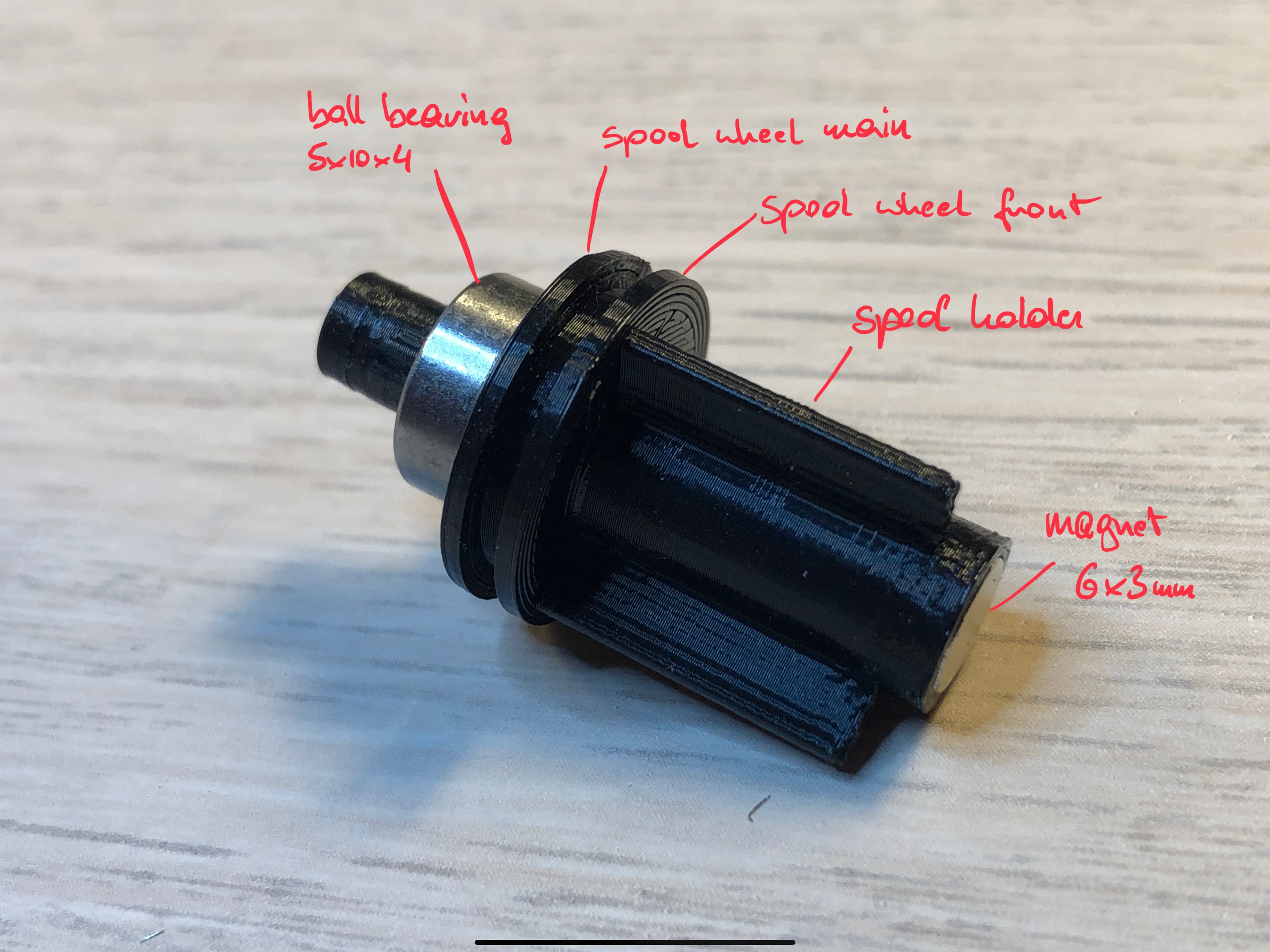
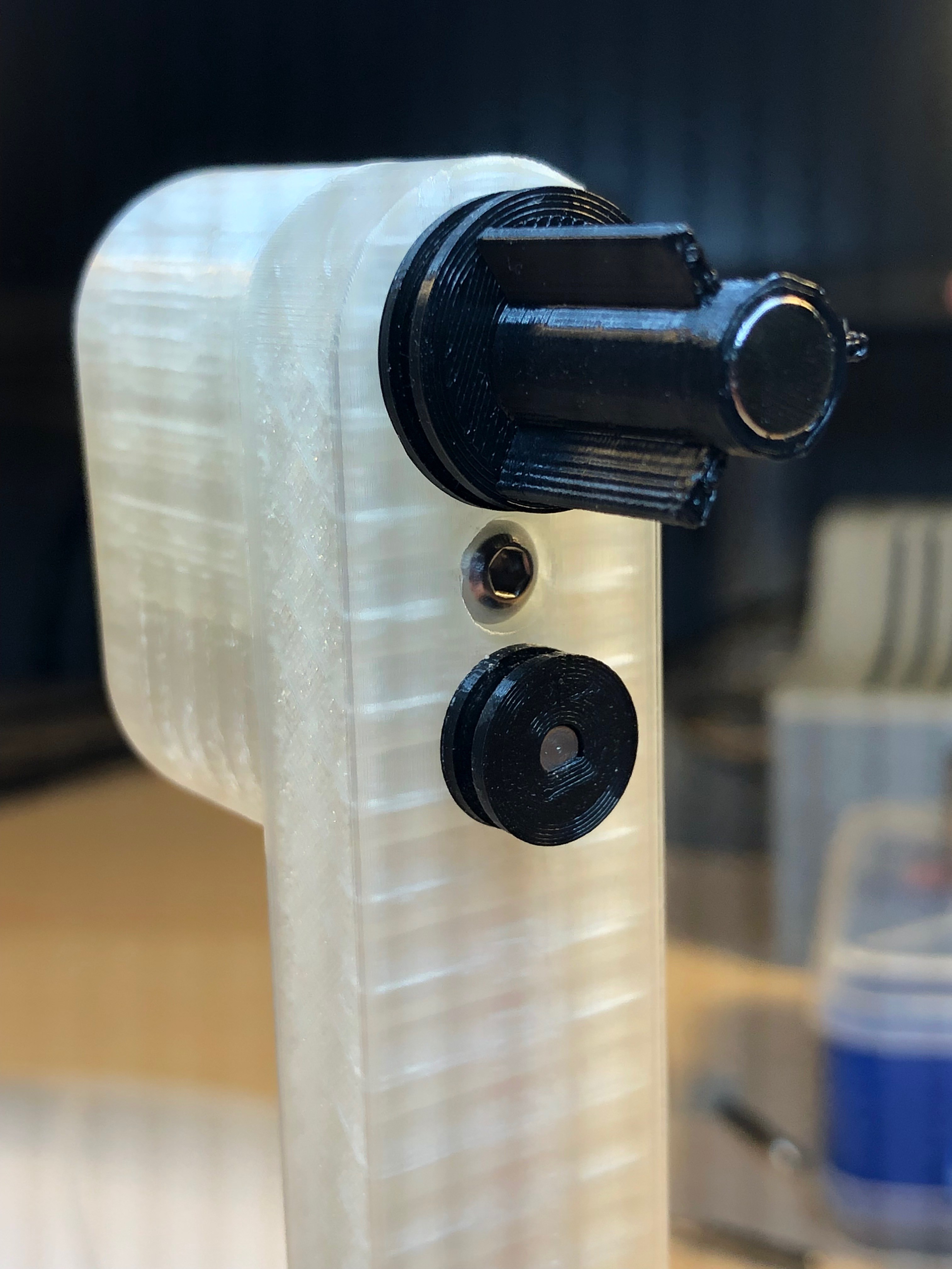
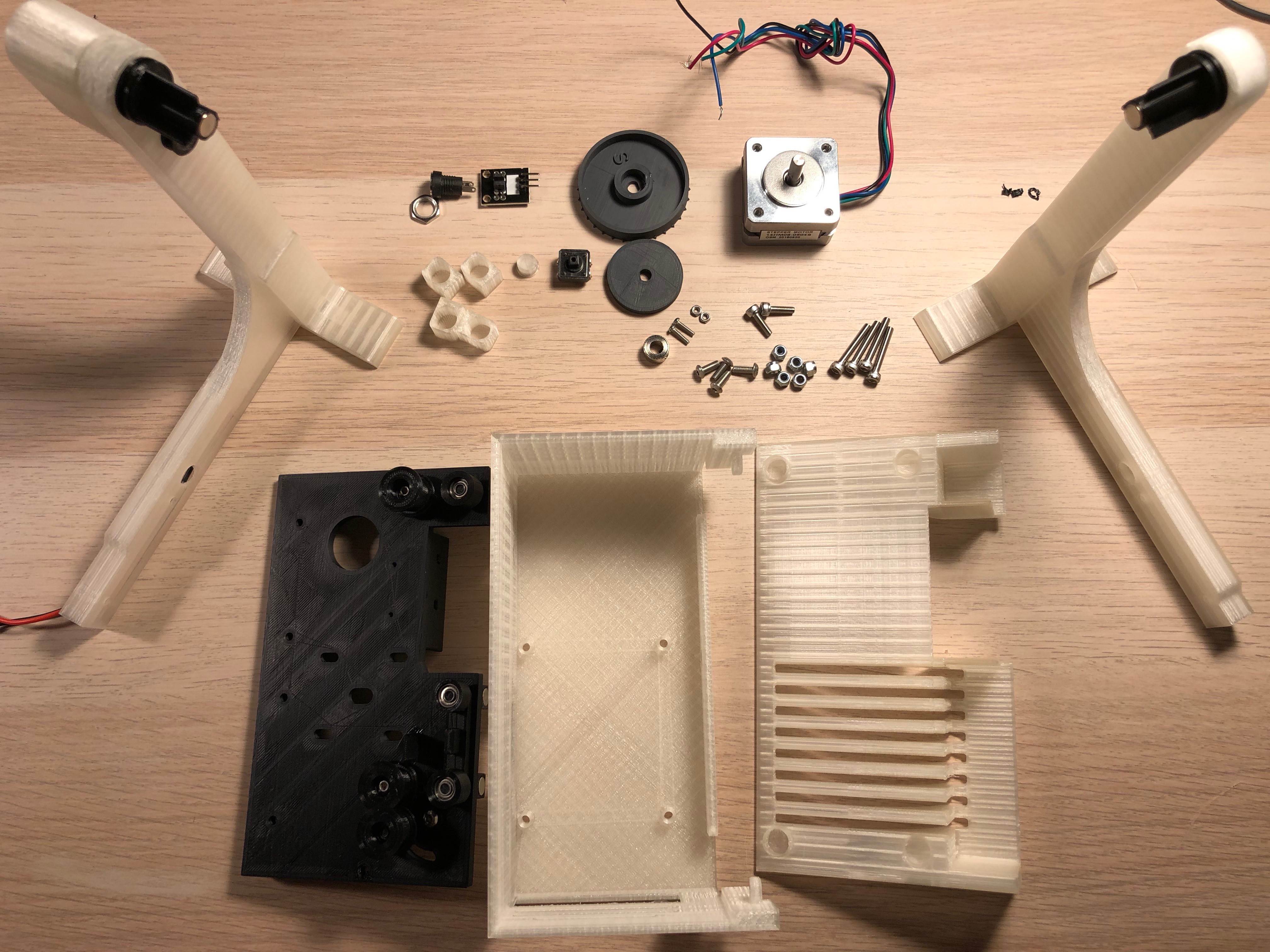
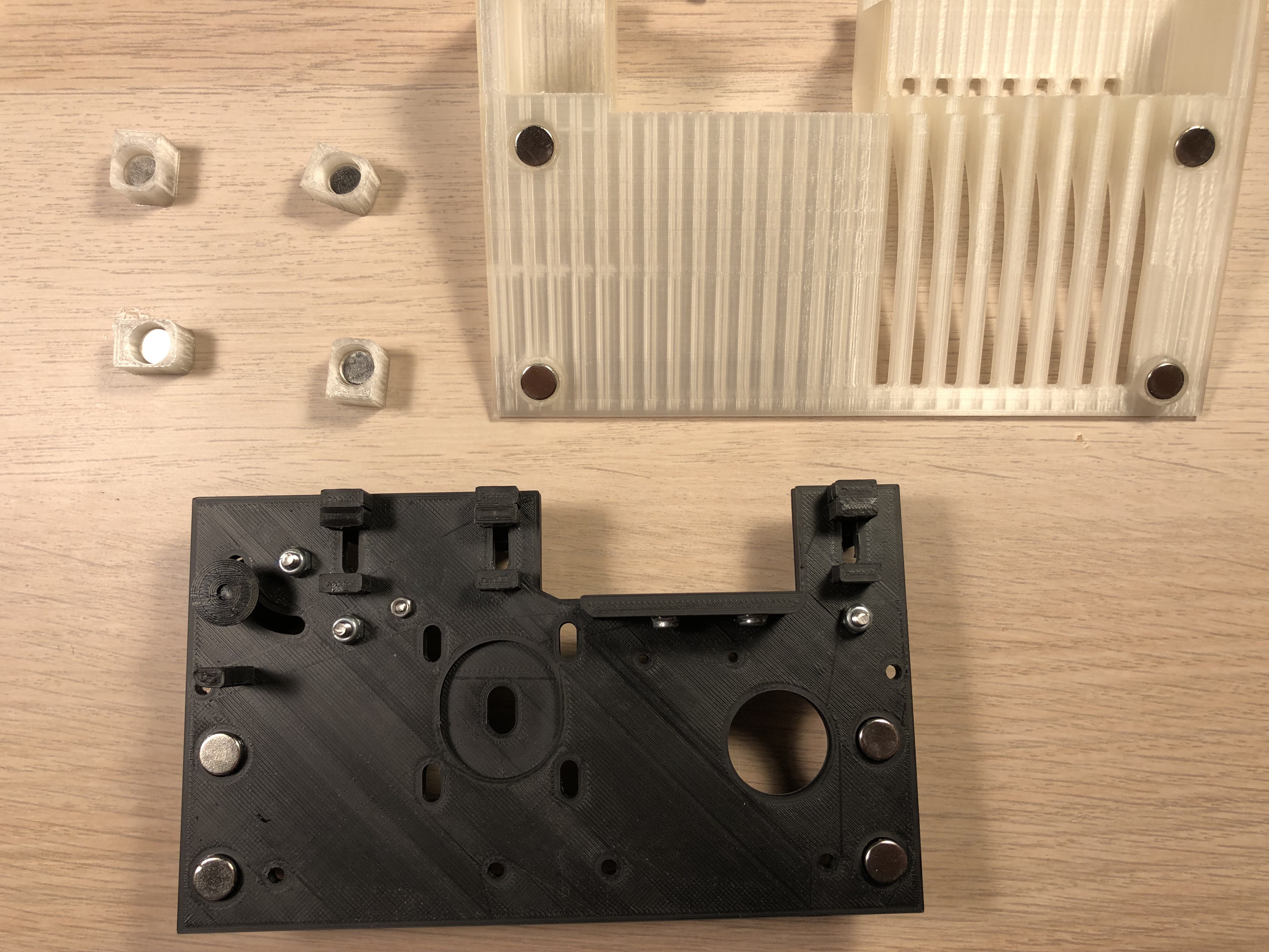
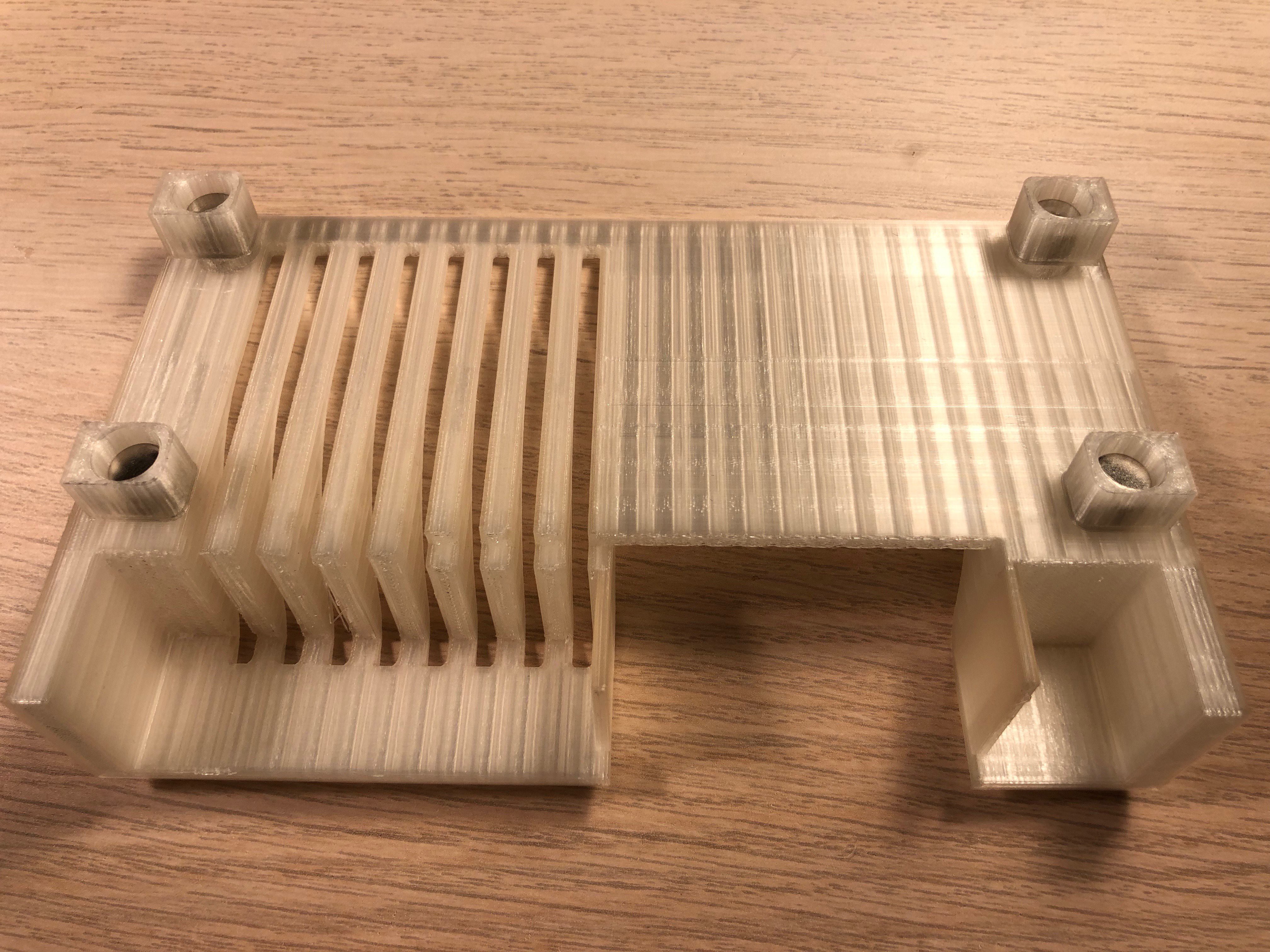
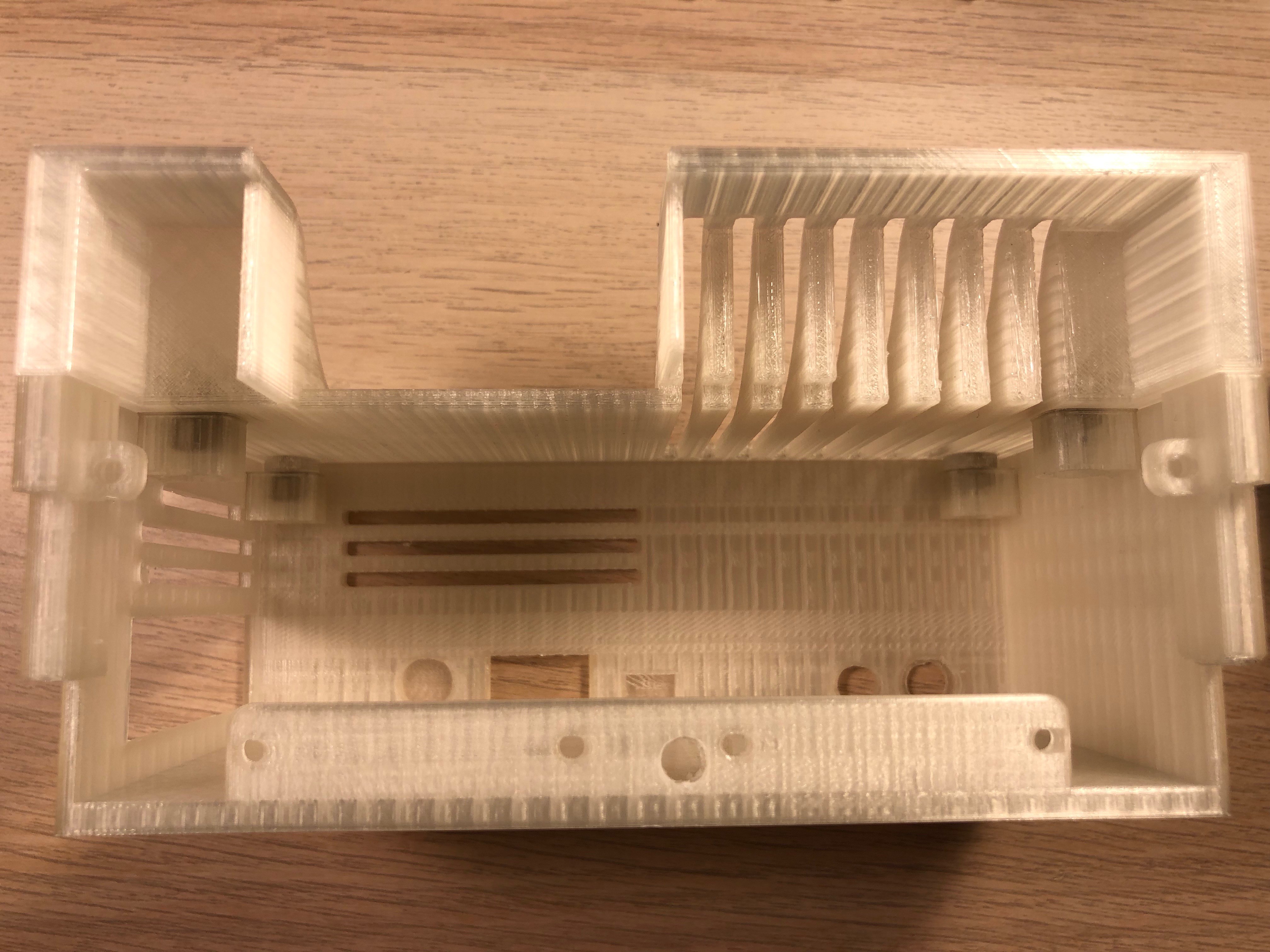
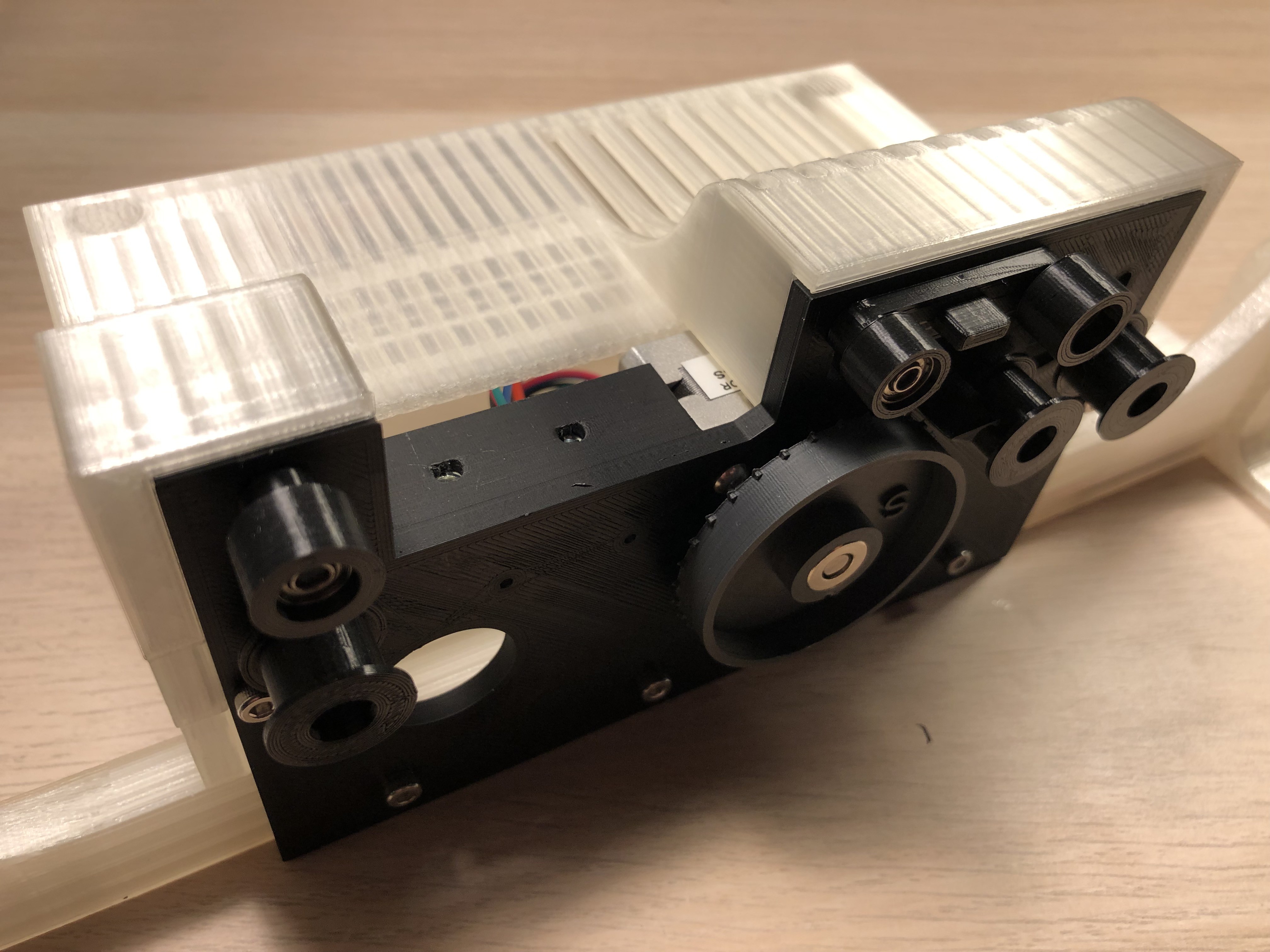
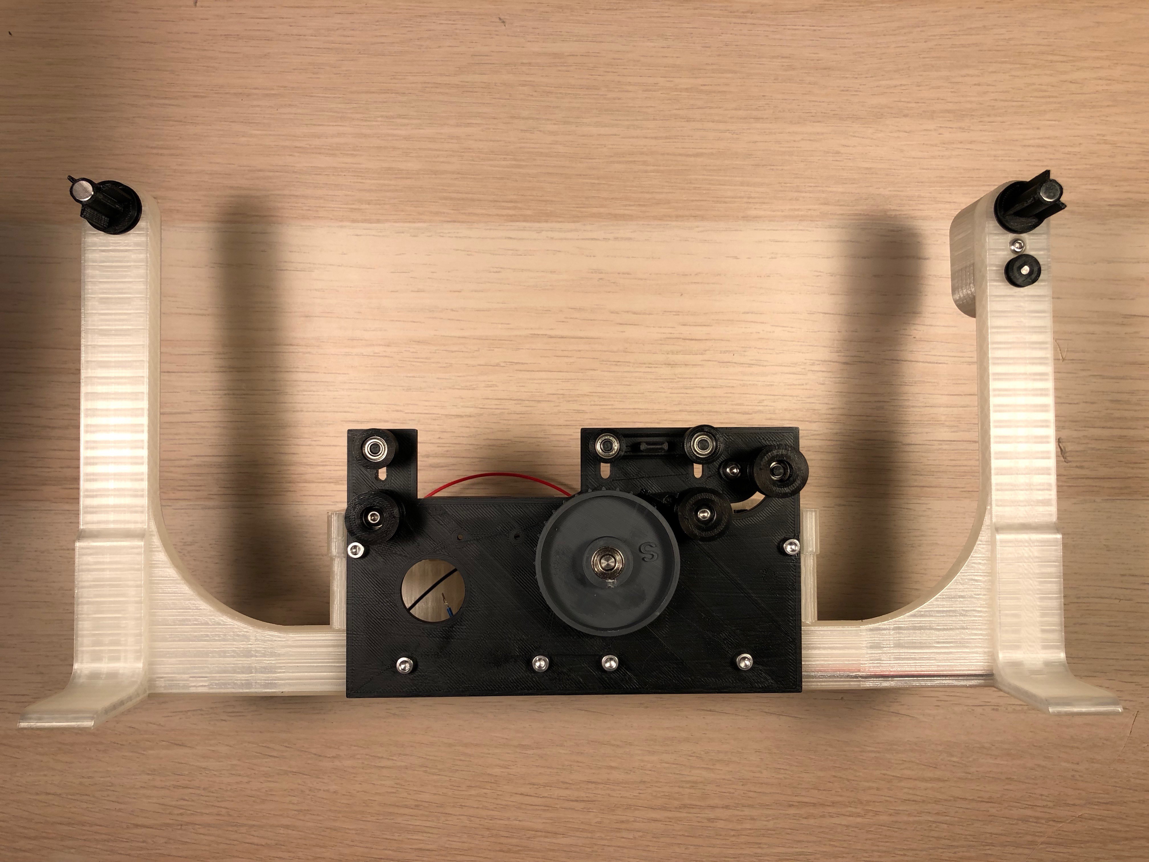

The 3D print:

Originally I printed everything in PLA. But after several hours of scanning I realised that the temperature of the stepper gets too high and some parts started deforming.

I printed the parts near the motor with ABS and that works just fine. (the stl files are sorted by material used)

OpenCV:

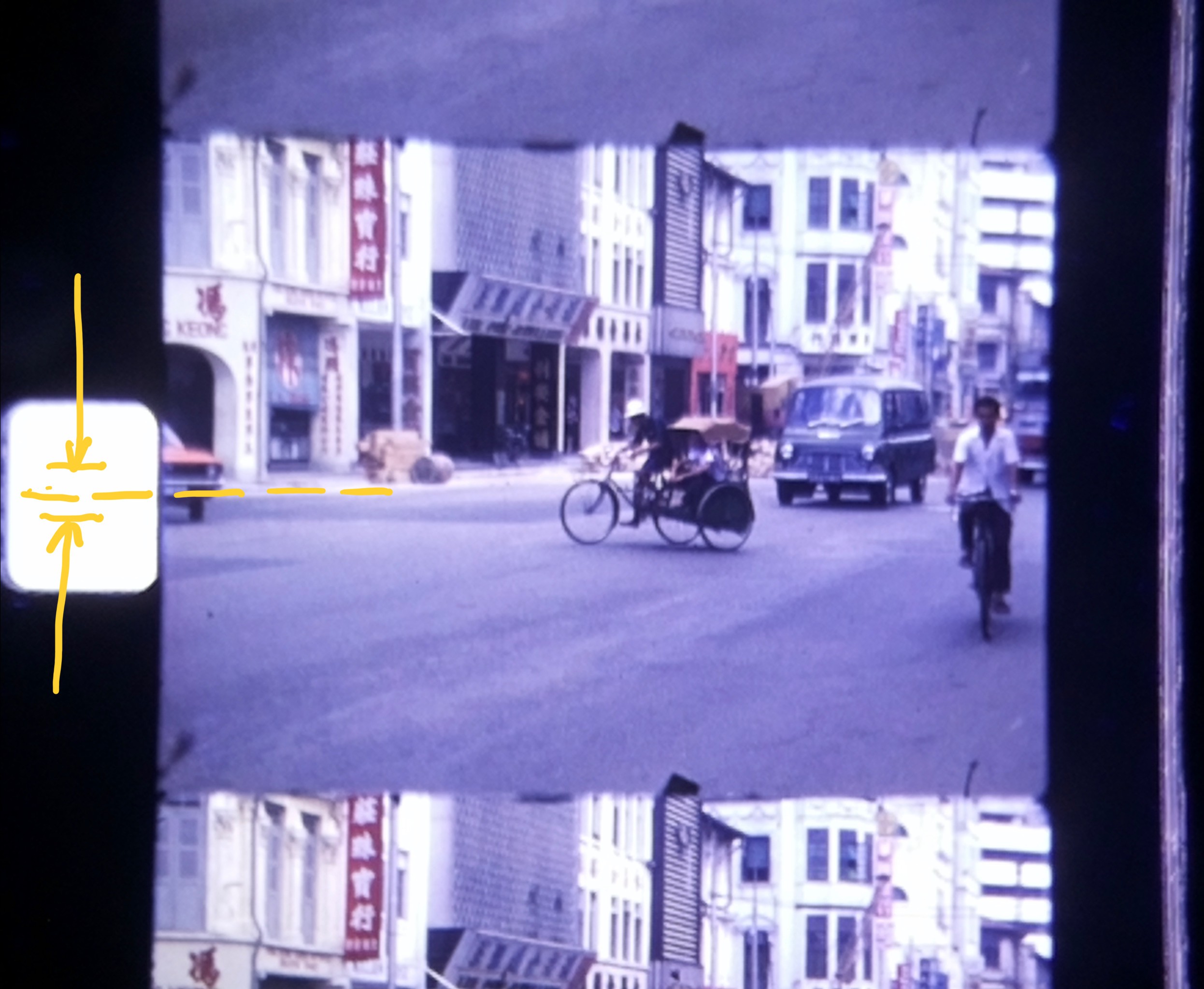
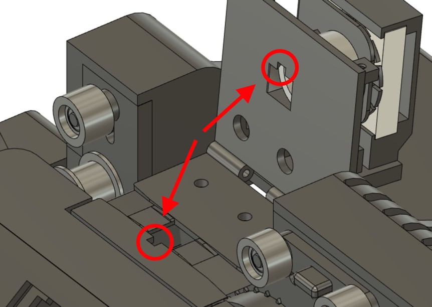
Even that the 0.9 degree stepper usually positions the frames very precise, there are variations especially when glued parts of the film, which are thicker, pass by. 

To ensure that the frames are always positioned in the middle of the cameras focus, I search for the contour on the left side - the sprocket hole in the film.

If that goes out of a certain tolerance, the stepper will readjust the frame.

scanned image

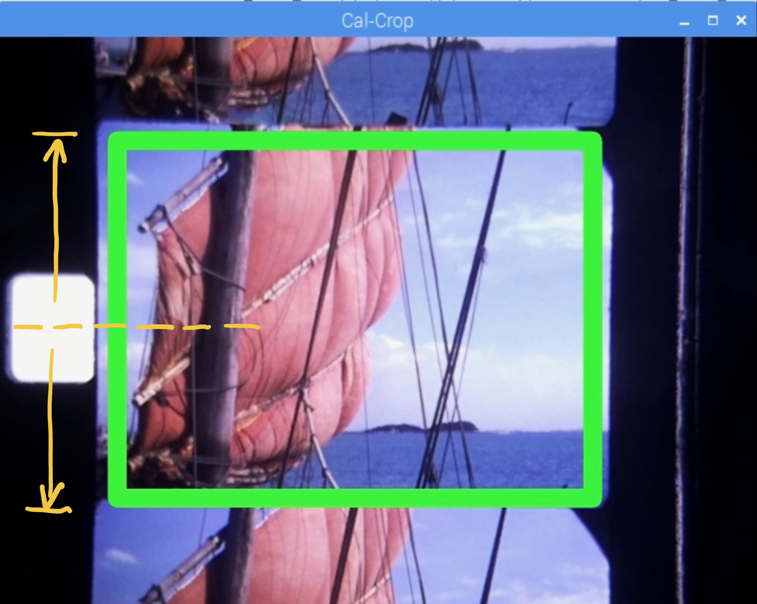
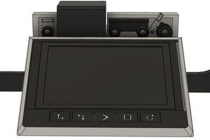
After scanning all the frames, the software goes in another mode - calibration and crop.

A rectangular frame (the green one) is moved to the desired part of the frame. This is necessary because the frame position relative to the sprocket hole is camera specific. 

After checking the right position of the rectangle with some random frames, the cropping is started with the push of a button. The frames are now cut out precisely and once done, they are put together with ffmpeg to a film.

image with calibration rectangle

film copier gen 7 v10.step

3D files for editing

step - 3.39 MB - 08/17/2021 at 09:23

Download

Zip Archive - 32.44 kB - 10/29/2020 at 05:36

Download

PCB.zip

PCB picture (pdf) files

Zip Archive - 60.01 kB - 05/13/2020 at 06:22

Download

Portable Network Graphics (PNG) - 532.58 kB - 09/07/2019 at 16:06

Preview
Download

  • 1 × Raspbery pi Model B
  • 1 × Raspberry Pi Camera V2
  • 1 × 3.5 inch 26P SPI TFT LCD Display Screen with Touch Panel 320*480
  • 1 × Mini N20 Micro Speed Gear Motor 6V 60 U/min
  • 1 × Photo Interrupter Sensor Module

View all 25 components

View all 10 project logs

  • 1
    Assembling the core

    Beside the printed parts on the picture, you'll need:

    Screws: 2pc M3x20mm, 1pc M3x12mm. 1pc M2x8mm

    Nuts: 5pc M3 Self locking, 1pc M2

    Magnets: 9pc 6x3mm

    Bearings: 6pc 3x8x4mm

    Glue the magnets into the holes of the mount plate as well as the 3 roll axles:

    Important! - Check the polarity: the axle hast to stick to the magnets in the mount plate in the upper and lower position.

    Magnets in Mount plate

    Push the bearings into the rolls: Don't worry to use some force - I use a vise for that.

    Afterwards glue the sides on the 3 larger rolls.

    all bearings in place
    assembled rolls
    using the vise

    Now put the axles through the mount plate and the roll mover (or roll spacer) and push the rolls on it. No need to adjust them yet. 

    Mount the 2 lower rolls with M3x20 screws and the interrupter lever with an M3x12mm screw. The film clearer is mounted with the M2 screw. Add 2 M3 nuts at the bottom of the latch (see picture of the back view)

    Ensure all rolls are running smooth and the upper rolls are locking in the upper and lower positions. 

    The result should look something like this:

    Front
    Back

    move on the step 2

  • 2
    Assemble the motorized spool holder

    Beside the printed parts as shown, you'll need the geared motor (6V 60U/min) a ball bearing 5x10x4mm a M3x16 screw + nut a magnet 6x3 (not on the photo) and some cable.

    Pull through the cables:

    Solder the geared motor:

    Put the nut in the motor cover:

    Put in the motor:

    Use the M3 screw to mount it to the arm:

    Assemble the spool holder by gluing the printed parts together and push the bearing on - it should sit very tight! Glue in the magnet. Important: You will find 2 very similar parts in your prints for the spool holder, one for each side. Here you use the slightly longer one.

    Push the holder into the arm - also here the bearing should fit very tight.

    Put the spool motor wheel main part onto the motor axle and glue the motor wheel front to the main. (not the axle)

    Assemble the 2nd spool holder and put it into the other spool arm.

  • 3
    Putting together what we've built so far

    You'll need screws: 4 M3x20, 2 M3x10, 4 M3x6mm, 6 self locking nuts M3, 2 M2x6 + nuts, 12 magnets 8x5mm, Photo Interrupter Sensor Module, the stepper motor, 1 Steel Shaft Sleeve 5.05mm, 1 DC Power Jack 5.5 x 2.1mm, 1 Button 12x12mm

    Glue the magnets into the holes:

    Polarity: the Magnets in the 4 magnet holder should stick to the magnets in the cover like that:

    Add a bit of super glue on the outer ends of the holders and put the cover on the back cover box, that way the cover will fit exactly on the box.

    Mount the power jack and the button. I use hot glue for the button. 

    Add the photo interruptor with the 2 M2 screws, the stepper with the 4 M3x6mm screws and mount the plate to the box. The M3x20 screws have to go through the mount plate, the spool arms and the box. 

    Push the sprocket back spacer on the stepper axle, a a few drops of glue onto it (the spacer - not the axle!) and push the sprocket with the shaft sleeve onto the axle.

    The cover should fit nicely and the magnets will hold it in place:

View all 8 instructions

Enjoy this project?

Share

Discussions

Stu wrote 05/13/2023 at 12:12 point

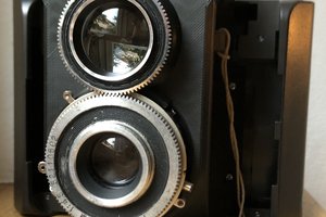
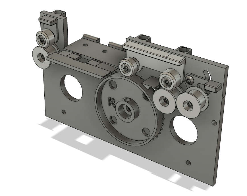
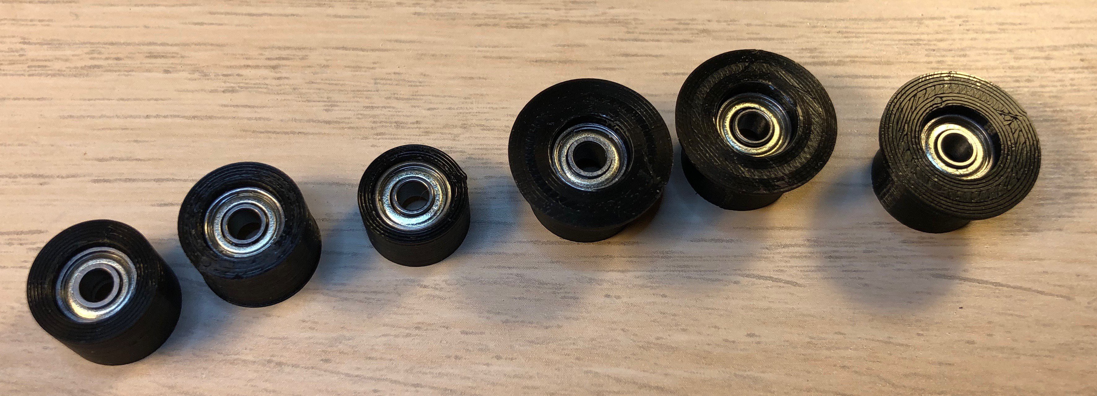
Anton - I came across your project last year after I had started on my own journey to build a Super 8 scanner.  Your design is very impressive, and after spending a number of months playing with a Geneva Wheel drive I have also decided to go with a stepper motor drive. It would help me considerably to understand your design if you could describe the film path through the various rollers etc.  I think I can see what happens, but I'm not sure what the item you label "Wheelmover large" does. I suspect it's to manage tension on the film. Can you please explain?  Regards

  Are you sure? yes | no

Lars Lund Hansen wrote 02/27/2023 at 18:42 point

 Hi Anton,

I discovered your
brilliant and very inspiring 8mm Film Scanner Projects for about 3 months ago. Now I have a working film scanner that has been able to
scan my 60 years old 8mm Regular films.

I had some problems along the way, but mostly with the software, and that lead me to starting my own software project:

“Program with a GUI for the Anton 8mm Film Scanner”.

https://hackaday.io/project/189773-program-with-a-gui-for-the-anton-8mm-film-scanner

I will continue to follow your V2 project, and look forward to see what comes next.

Best Regards

Lars

  Are you sure? yes | no

Anton wrote 03/25/2023 at 09:39 point

Hi Lars,

sorry for my late reply ... I'm quite swamped with work, hence also the delay at the V2 of the project.

Very impressive work - I really like the idea of a program with a GUI.

I also find the clip you posted interesting. Seems the camera also captured within the area of the holes.

I hope I find time to continue on V2, even that it doesnt look to promising right now. Would be a pitty, because I have already the fully assembled new electronics ready for extensive testing ...

best regards

Anton

  Are you sure? yes | no

the95collector wrote 02/15/2023 at 10:04 point

Hello Everyone....I am guessing that this is a project that could be adapted to scan 9.5mm cine film?

  Are you sure? yes | no

André wrote 02/08/2023 at 13:51 point

  Are you sure? yes | no

Andrej Rolih wrote 12/26/2022 at 13:01 point

Have you ever considered expanding this to fit other film types? What I would be very interested in is 35mm. Especially since you can find 35mm film trailers on ebay relatively cheaply. And it would be kind off fun trying to digitize those (even though you can get properly digitized versions of those anyways).

  Are you sure? yes | no

oldpeter wrote 10/10/2022 at 12:30 point

Hi to all.

I'm new here so please be patient. I'm an old man.

 And now the first question.

Anyone out there who knows where to find the latest version of the Gerber File and the PCB Layout ?

What I get was the one without the switch R8/S8

  Are you sure? yes | no

Mauricio Tecles wrote 05/17/2022 at 23:02 point

Hi Anton!
I have been studying your very nice project for some time. My first idea was to hack my old Bell & Howell 253A 8mm projector (1956). The biggest problem with that is the optical part. Lens (focal distance) and camera are hard to fit in the projector and they are kept away (43mm minimum) from the film (sprockets and objective housing are in the way).
I am considering adapting  your project to Arduino as I have an Arduino Mega and a NEMA 14 stepper motor. I would use my computer to process the image, which brings me to the camera and lens, probably Arducam 5MP Plus OV5642 Mini Module.
1-Which lens and mount base did you by with your V2 camera?
2-Have you used just the Mobile Phone Macro Lens 20X (Snapun) or in addition to the V2 lens?

Thank you for sharing your work!

  Are you sure? yes | no

Anton wrote 05/18/2022 at 05:39 point

Hi!

I’ve used the original Raspberry camera V2 + the macro lens.

Arducam has a great variety of lenses, maybe there is one that can donthe job without the additional macro lens?

Your approach sounds very interesting- please let me know how it goes from time to time if you don’t mind.

BR, Anton

  Are you sure? yes | no

Mauricio Tecles wrote 05/18/2022 at 12:22 point

Thank you! I will!

  Are you sure? yes | no

Doug Bidault wrote 03/16/2022 at 03:47 point

Hi Anton,

I've been quietly following this project for a few years now.  I've built the hardware and have everything working with the test code, so far so good.  I am at a point where I would like to scan some film, but my primary interest is regular 8 and I don't even have any super 8 film to play with.  Are you still working on the regular 8mm implementation and do you have an idea when you might have some code to try?  

Thanks,

  Are you sure? yes | no

Anton wrote 03/18/2022 at 02:39 point

Hi Doug

I wish I'd have some more time to completely rewrite the code. Its quite a mess - doing its job but only for S8. In order to scan R8 (beside using the other sprocket) the step_count needs to be adjusted, which can be done easily, but the bigger topic is to change the part where opencv checks the sprocket hole. The position from the hole to the picture is different. You could just skip it all together and scan your films, but in this case you will need to post process the frames with another tool such as final cut.

Rewriting the code is something I really would like to do, I just cannot see that happening anytime soon due to time constrains on my end. (Maybe someone else has done it already?) Once I do I for sure will post it here. 

  Are you sure? yes | no

Doug Bidault wrote 03/19/2022 at 03:52 point

Hi Anton,

I wish I was better with software, I'm more of a hardware guy.  If I want to play around with just scanning the film without using the sprocket info, is there any changes I need to do to the code?  So far I've had an error when I try running it, It's the same error that "thejerry" posted last year.  I haven't had time to look into it yet but hopefully I'll get to it this weekend.  

  Are you sure? yes | no

Anton wrote 03/20/2022 at 07:38 point

Hi Doug

I just posted a new version for S8 scanning. I cleaned it up and I hope I will soon find the time for a R8 version. Your post motivated me to do the cleanup! :)

  Are you sure? yes | no

Anton wrote 03/20/2022 at 12:10 point

I just posted a version for regular 8

  Are you sure? yes | no

Doug Bidault wrote 03/22/2022 at 00:27 point

Hi Anton,

 I'm glad that I was able to help provide some motivation.  I've looked over some of the new code  and I'm looking forward to using it. 

  Are you sure? yes | no

Ron wrote 01/23/2022 at 14:08 point

Hi Anton,

I am verry interested in the files of the sprocetwheel and filmgate. I only saw the complete machine. Is this due to my lack of knowlage about 3d files? 

Is it possible to download only the sprocketwheel and filmgate?

Thanx in advance.

Ron.

  Are you sure? yes | no

giancarlo wrote 01/23/2022 at 14:39 point

Hi Ron,

is one of theses files are you looking for?

https://drive.google.com/drive/folders/12FbLeUzjyGKtjXjXixvxCzoX2PF9MoqZ

You can convert it with online tools from stl to dwg

  Are you sure? yes | no

Ron wrote 01/23/2022 at 19:22 point

Thanx!

  Are you sure? yes | no

Anton wrote 02/13/2022 at 22:42 point

Hi Ron! If you download the .step files in e.g. fusion 360, you have all components - from there you select the one you want to work on. Its easier to use the .step format than stls

  Are you sure? yes | no

jfoust wrote 01/21/2022 at 14:16 point

Instead of all the hassles of sprockets, what about the idea of a friction drive (such as a rubber roller) along the sprocket edge?  I know, purists don't want anything to touch the film.  But claws and teeth depend on film sprockets not being worn or torn.  

Instead of trying to design a reliable mechanical method of precisely aligning film frames to the camera optics, what about a more continuous drive?  Moving the film a known small amount, a fraction of any film frame, taking a pic, and then letting OpenCV find the film frames and glue them back together?  

And this could process optical audio, too.  And a continuous feed would also make it possible to add a magnetic head to handle that kind of audio, too.  Or having a gate that can handle 8mm, 16mm, 35mm?  Or what about controlling the LED backlight brightness and taking several exposures instead of one, and squeezing more HDR depth out of an 8-bit camera?  

All of us here probably have a powerful PC with GPU and plenty of fast storage, so why not do all the post-processing on a paired PC?

  Are you sure? yes | no

giancarlo wrote 01/23/2022 at 14:34 point

Hi Jfoust,

I have made some test of HDR with the PiCamera V2 but instead of changing the LED light I have changed the shutter_speed of the Camera.  The result is good.

I was also proposing replacing the 8Mpixel camera with the 12Mpixel one. 

For the post-processing is of course better to use a PC. 

  Are you sure? yes | no

giancarlo wrote 01/05/2022 at 17:21 point

Hi,

very interesting project. I'm printing the 3D parts and buying the components. I have some question about the following components:

1) DC-DC Buck Converter Step Down Module: In the  component list I didn't found the exact type of converter: Input voltage, Output voltage, Power or output current?

2) Stepper Motor: I saw the microstep is set to 1/8 step. Is it possible to use a stepper motor with 1.8° step and a better microstep (1/16 or 1/32)?

3) Mini N20 Micro Speed Gear Motor 6V 60 U/min. Do you have a reseller for this motor?

4) Raspberry Pi Camera V2. I would be interesting using the 12.3MPixel one (Raspberry HQ) (https://www.raspberrypi.com/products/raspberry-pi-high-quality-camera/)? The PCB is larger and also the HQ version need lens. But the quality would be better (better noise ratio)

  Are you sure? yes | no

giancarlo wrote 01/16/2022 at 12:36 point

Hi again. I found that the DC/DC is a Uin=9V Uout=5V 3A

  Are you sure? yes | no

Anton wrote 02/13/2022 at 22:52 point

thats correct ... 9V is for the stepper, 5V for the pi. 

  Are you sure? yes | no

Anton wrote 02/13/2022 at 22:48 point

Hi giancarlo

2) - yes, just change the code accordingly (#of steps)

3) I bought it on aliexpress - do you need the exact reseller?

4) when I made it, there was no raspi HQ camera. No doubt the quality should be better. However, it will need significant changes on the model due to the size of the camera 

  Are you sure? yes | no

giancarlo wrote 02/16/2022 at 07:57 point

Hi Anton,

3) I found it on aliexpress.

https://de.aliexpress.com/item/1005003482247510.html?gatewayAdapt=glo2deu&spm=a2g0o.9042311.0.0.21a34c4d4e4Dmf

It should be the right one

  Are you sure? yes | no

davidhhanes wrote 12/31/2021 at 17:14 point

I am having a friend 3D print the parts now, and have the PCB ordered as well. I'm having trouble finding a source for the correct "L9110H motor controller" form factor. Does anyone have a good source for this?

  Are you sure? yes | no

giancarlo wrote 01/05/2022 at 17:00 point

Hi, it should be a DIL8. You can buy it from different sources like:

https://www.reichelt.com/ch/de/current-mode-pwm-regler-1-a-12-30-v-250-khz-dip-8-uc3844bng-p309602.html?PROVID=2808&gclid=Cj0KCQiAoNWOBhCwARIsAAiHnEgdOUPjL0BqnRBmfL35nCNL5FkDC0Lu0A8AgMRqqDcH0RgHvlXUUZ8aAqQfEALw_wcB

or

https://www.digikey.ch/de/products/detail/adafruit-industries-llc/4489/11594498?s=N4IgTCBcDaIDIE4CMSAMAJEBdAvkA


or

https://www.ebay.de/itm/2PCS-L9110H-LG-DIP-8-Full-bridg-e-Driver-H-Dridge-Driver-Motor-Driver-IC-/263562465103?var=0&mkevt=1&mkcid=1&mkrid=707-53477-19255-0&campid=5338268676&toolid=10044&customid=Cj0KCQiAoNWOBhCwARIsAAiHnEga5D4a8ApiiyDelhOzQrKc1yAJwLqDJJdaIfbOQQ2gLGY5rzuXpMkaAhOREALw_wcB

  Are you sure? yes | no

domenico wrote 11/27/2021 at 08:56 point

Awesome project Anton. Thank you for sharing, I will definitively make use of your experience on this project to scan my dad's old home movies.

  Are you sure? yes | no

sixpack-de wrote 11/25/2021 at 09:10 point

Really cool Project, maybe I am blind (or stupid) :) , but is there a link to the stl files, or do I need to export them out of fusion? 

  Are you sure? yes | no

Anton wrote 02/13/2022 at 22:51 point

Hi! there is indeed a link for the stl files (left side under the team names) - but in case you cant find them: https://drive.google.com/drive/folders/1fFjKV_zjYW72i-uLE7GsnJ5kvQ_yrD6i

  Are you sure? yes | no

TomW wrote 11/19/2021 at 19:16 point

Any thoughts on adding sound?

  Are you sure? yes | no

Anton wrote 11/20/2021 at 02:35 point

this is something I'm also thinking about since I found several reels with sound track. I guess I'll see if I can find an old used projector on ebay that still at least can play the sound. I would record it and add it to the film "manually". Adding it to the build would be challenging, since the audio track needs to be read in real time, while the film is scanned frame by frame.

  Are you sure? yes | no

haleyma wrote 11/19/2021 at 15:23 point

Really enjoyed the story of your build journey.  I keep lapsing back to Tinkercad and am curious what resources you used to learn Fusion 360?

  Are you sure? yes | no

Anton wrote 11/20/2021 at 02:31 point

Thank you - glad you enjoyed the story. I remember the switch from Tinkercad to Fusion very well. I was so frustrated and really thought that fusion is just too complicated. I watched tutorials on youtube (e.g. https://www.youtube.com/c/ProductDesignOnline ) and then just tried and tried and suddenly it seemed totally logical and easy to me. I guess there was some "unlearning" necessary coming from Tinkercad, where you design with objects vs fusion where you use sketches. Don't give up - its totally worth it :) 

  Are you sure? yes | no

haleyma wrote 11/20/2021 at 14:51 point

Thanks!

  Are you sure? yes | no

thejerry wrote 07/16/2021 at 17:08 point

So I am on the end of HW journey. I finished build and I am trying to scan something. S8_Test_V2.0.py works perfectly. No issue there. When I tried S8_scan_OCV_V2.0.py it showed error "contours,hierarchy = cv2.findContours(thresh, 1, 2) ValueError: not enough values to unpack (expected 3, got 2)", I found that this line is maybe outdated after some updates of OpenCV, so I tried change that line with help of this discussion https://github.com/facebookresearch/maskrcnn-benchmark/issues/339#issuecomment-551012412 .. I didn't show this error any more but I have new one and I am stuck :/ 

cnt = contours[l] IndexError: list index out of range

I tried to change it to 2000. Didn't help. What this could mean? I am not programmer, so I can only guess. Maybe it can't recognize frame?

I am using HQ camera and I didn't change nothing else in the S8_scan_OCV_V2.0.py.

  Are you sure? yes | no

thejerry wrote 07/22/2021 at 10:36 point

I am pretty sure it was because of blob wasn't bright enough. I move LED little bit higher and add some brightness in camera settings. Looks like it helped.

I still wasn't able to make full scan. It seems to me it goes sometimes more backwards then forward and after some while of backward movement sprocket loose contact with film and scanning is stopped. 

  Are you sure? yes | no

Lazyfattree wrote 05/05/2021 at 11:13 point

BOM list with links to the components to buy would be interesting. 
I'm really excited to make 1 and then alter it for Super 8 aswell 

  Are you sure? yes | no

thejerry wrote 03/14/2021 at 18:57 point

I am gonna try to use new HQ camera. Before I am gonna start, is anyone here who successfully updated this great machine with HQ camera?

  Are you sure? yes | no

Richard Stevens wrote 01/11/2021 at 22:24 point

Really cool project, thanks a lot for sharing. I'm planning to build this and currently sourcing the parts. Two questions:

1.) I'm having a hard time sourcing the acryllic. 1mm seems to be difficult to get. Does anyone have an idea where to order it in Germany/Europe?

2.) I have a couple of optical endstop modules left over from my printer build. Is this what's needed? 

UPDATE:

And I have a third question. I printed the sprocket gear on my SLA printer. The stepper hole fits perfectly. Also measured, the dimensions seem to be spot on. However the sprockets themselves do not properly align with the film. A few do but then it starts to get misaligned. Does anyone else have a similar situation? Am I doing something wrong? 

I had this on the same plate: https://www.thingiverse.com/rstcologne/collections/super8

and it fits perfectly. 

Thanks a lot,

Richard

  Are you sure? yes | no

Anton wrote 01/15/2021 at 01:44 point

Hi Richard

the acrylic sheet I used was from ali ...

to the sprocket: there are 2 versions regular 8 and super 8 - sure you use the correct one?

  Are you sure? yes | no

Similar Projects

Does this project spark your interest?

Become a member to follow this project and never miss any updates