Close
0%
0%

MODBUS Things with STM8 eForth

Projects (and mishaps) for talking MODBUS to STM8 eForth

Similar projects worth following
Doing things with MODBUS should be easy but using ultra-cheap Chinese MODBUS boards is anyting but. It's as much "hacking" as "reverse hacking" (engineering is to big a word) to figure out where those addressing a hobby and informal engineering market made a joke of specifications and protocols, even the most simple ones. In this project I'm having fun with these things by using them with STM8 eForth. Why not innovate a bit while we're at it?

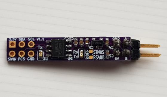
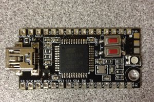
MODBUS, especially the binary serial RTU protocol through RS485 interface is still popular - sufficiently popular to create a market for ultra-cheap (hobby-grade) components, e.g. "STM8S103 Relay Control Board" with barely usable MODBUS firmware


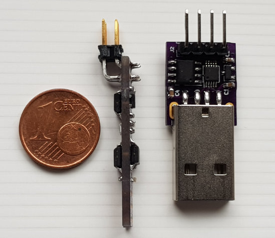
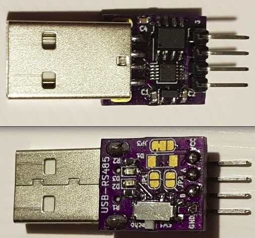
or the infamous Chinese "USB RS485 Adapter Black+Green" for less than $1 (including shipping).

For some time now I had fun with implementing MODBUS, testing it against frameworks and getting things running (or not) using Chinese gadgets. It turned out that finding the culprit sometimes takes time.

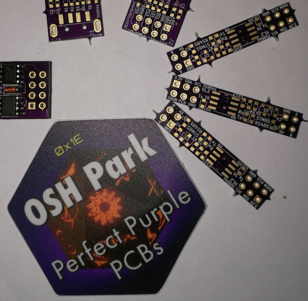
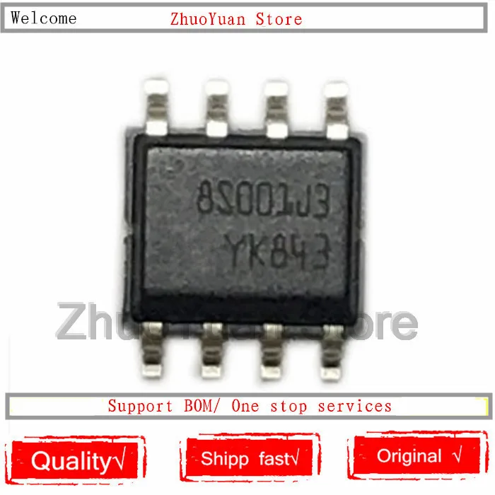
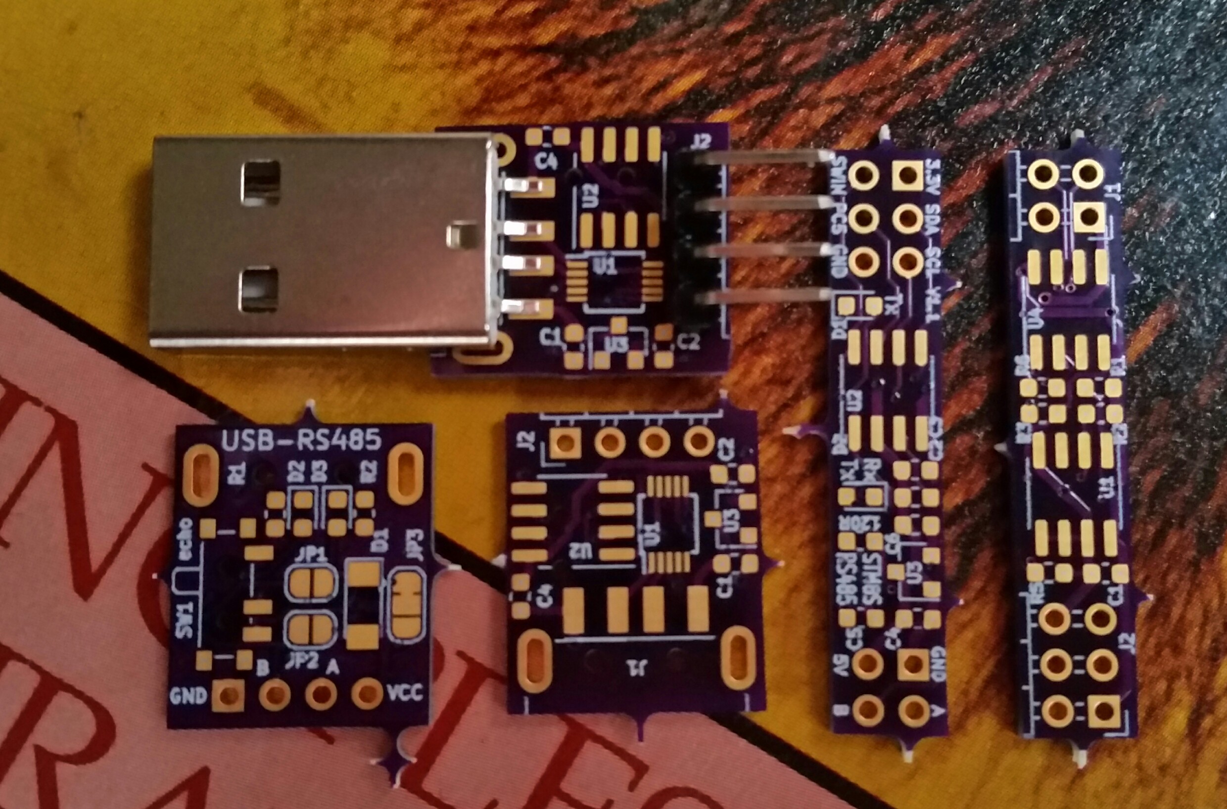
Lately, I played with KiCad, more for occupational stress relief than for creating something useful. But what the heck, why should this small STM8S001J3 MODBUS node disappear in the stream of the @oshpark  shared projects list, eceiving no love?

STM8S001J3_RS485_back.pngThis project shall make some attempts more visible and it I hope that it will lead to a usable platform soonish.

  • Doing more with STM8 eForth MODBUS - a Video and Client Experiments

    Thomas07/04/2022 at 04:54 0 comments

    Unlike many other sources of Chinese modules with STM8 chips the good old C0135 MODBUS-RTU 4-Relay Boards with STM8S103F3P6 chips are still available for a fair price - and with the right software they're still a great stock component for small automation tasks.

    I had been invited to talk about how to interactively develop MODBUS Server an applications with STM8 eForth. In MODBUS lingo a "server" is a node that listens to a MODBUS Client. 

     
    Even if the server does its own thing (e.g., not just issue NEC-IR codes like in the demo above but also, say, react on ambient light or local user input devices), there is still a thing missing: actively send data to anther node. We can call that a MODBUS client - but why not to call it a peer?

    It's true, the MODBUS-RTU protocol was never designed for multi-master operation but that doesn't mean that with a tiny bit of protocol and timing on top it can't be used to freely share bits of data between nodes.

    First experiments are very promising (requesting and receiving data works). While experimenting with the MODBUS client code I found and fixed a bug that made the node release the bus too early in the first transmission after reset.

    In order to enable implementations of FC23 ("Read/Write Multiple Registers") the FC->XT table encoding was improved.

  • New STM8S001RS485 PCBs V1.2 arrived from OSHpark

    Thomas02/16/2021 at 06:42 0 comments

    As mentioned in the last log entry, I fixed a minor issue with the RX/TX LED of the STM8S001RS485 MODBUS node and ordered the $1.65 PCB together with my latest key-chain Forth USB dongle so that the amount of the order was above the threshold where I deem it ridiculous (well, at $3.65 including shipping it maybe still is). Shipping through USPS would have taken >5 weeks (plus up to 12 days for making the PCB of course), and I was totally OK with that...
    ... until someone from @oshpark offered me a free upgrade to Super Swift service (5 business days) AND the FedEx "URGENT" delivery services (I knew that these guys are great!).

    From KiCad file to "PCBs in a German mailbox" it took just 8.5 days after I pressed the order button!

  • New release 0.20, STM8 eForth updated to 2.2.27.pre2, better board support pattern

    Thomas02/06/2021 at 18:30 0 comments

    A request from @niuyingxian for STM8EF-MODBUS support for the STM8S001J3RS485 board was a good reason to finally apply some of the improvements in STM8 eForth 2.2.26 for improving board support. One of the challenges addressed by the current STM8 eForth release was dealing with STM8 device hardware dependencies. While working on the code I realized that moving from Ubuntu 16.04 to 20.04 removed Python 2.7 support, which made using the current development version 2.2.27.pre2 necessary. STM8EF-MODBUS uses the "modular build" method, and "make depend" automatically loads the configured STM8 eForth release.

    The top level Makefile now handles multiple board variants at the top level, and targets are split between "MODBOARD" and "BOARD" targets:

    • The MODBOARD targets work on the STM8EF-MODBUS level: targets work on the Forth code level, but they also build the Forth core for a board configuration folder: "make MODBOARD=C0135 load" first builds and transfers the code (using stm8flash and an ST-Link V2 dongle), then it uses codeload.py to transfer the code
    • Building the STM8 eForth forth.mk targets still work by setting BOARD, e.g. "make BOARD=C0135 flash"
    • The target for starting an interactive e4thcom session is "make term" and there is also a target for build, loading and binary generation of all supported targets using uCsim and simload.sh (e.g. in Travis-CI using a tg9541/docker-sdcc container, that's how the GitHub binary release is made)

    On the target support side, I added a board.fs and BUSCTRL for the STM8S001J3RS485 board:

    STM8S001J3M3 MODBUS moduleThe Forth console communication works with a simulated serial interface through PC5 (J2.4). The way the UART is used for the RS485 communication (RX/TX through PD5 in "half duplex mode" and direction through PD6) created a spurious RX receive event when switching the bus from TX back to RX. A dummy read of UART_DR and toggling the RX interrupt enbale in BUSCTRL solved the problem.

    There is one minor hardware issue with the RX/TX LED: it has the bus activity the wrong way, i.e. it's lit when the RS485 bus is idle. A new board revision V1.2 will fix that.

    I also tested the code with a C0135 - everything should work as expected.

  • An STM8S001J3M3 "deal": 10 for $2.55, free shipping

    Thomas08/22/2020 at 11:02 3 comments

    STM8S001J3M3 chips are easy to solder and they're powerful enough for small MODBUS nodes, and for interactive STM8 eForth nodes, too.

    Since free shipping from China has almost tried up, these chips have become more expensive. A good price with free shipping is an opportunity for stocking up worth sharing.

    This chip can be used with the very small MODBUS board available from @oshpark, three of which cost just $1.65 (but at that price please order some more OSH boards or else the PCBs will feel really lonely in the large bag).

  • C0135 Relay Board: a beta release

    Thomas05/01/2020 at 08:55 0 comments

    For the C0135 relay board there is now a beta release that implements the following FCs:

    FC01     Read Coils
    FC02     Read Discrete Inputs
    FC03     Read Holding Registers
    FC04     Read Input Registers
    FC5     Write Single Coil
    FC6     Write Single (Holding) Register
    FC15     Write Multiple Coils
    FC16     Write Multiple Registers

    I ran tests with QModMaster and also made sure that the installation is feasible for people who don't care much about the implementation :-)

    The entry point for "general audience" is the link to MODBUS RTU releases on the C0135 Relay Control Board page in the STM8 eForth Wiki.

  • C0135 Relay Board: Inputs working

    Thomas04/24/2020 at 09:20 0 comments

    I just added the STM8 eForth MODBUS pre-release 0.16 that not only supports FC-2 "Read Discrete Inputs" but also actually reads C0135 "4-Relay Board" inputs (finally).

    Unlike writing board outputs with OUT! words for reading inputs have never been part of the STM8 eForth core. It's been a while since output words coded in assembler were moved into boardcore.inc. Since the new modular build supports binary GitHub releases with Forth code there is no reason anymore for coding board support words in assembler.

    I just added IN@ in Forth for supporting low-active inputs (NPN in PLC lingo):

    \ opcode: rotate C left through TOS lsb
    : RLC(1,X) $6901 ,  ; IMMEDIATE
    
    \ read C0135 inputs - connect INx to GND to get a "1"
    : IN@ ( -- n )
      -1  \ inputs are "NPN" (in PLC speak), start with all bits 1
      [ ( IN4 ) PC_IDR 6 ]BC RLC(1,X)  \ some simple STM8 assembly
      [ ( IN3 ) PC_IDR 7 ]BC RLC(1,X)  \ to load bits to C
      [ ( IN2 ) PD_IDR 2 ]BC RLC(1,X)  \ and rotate them into the
      [ ( IN1 ) PD_IDR 3 ]BC RLC(1,X)  \ Top Of Stack low-byte
      NOT
    ;
    

    Ok, I have to admit that this is almost assembler but IN@ is more readable than an implementation in C. I like C but low level routines, and the code they produce, are a frequent source of concerns, compiler bug reports, #pragmas, syntax extendsions and idioms without adding the least bit to portability (even if your intent is to exchange compilers, not hardware).

    Using this is as simple as always: IN@ will return a bitmap containing the inputs.

    The following "program" will activate a relay if the corresponding input is pulled low:

    \ copy inputs to outputs
    : doit ( -- )
       IN@ ( n ) OUT! 
    ;
    
    ' doit BG !  \ run in background

    The background task makes this task surprisingly easy. Note: everything ( in brackets ) and after "\"  are comments.

    Adding a simple state machine already allows doing some interesting things.

  • A Binary Release for the C0135 "STM8S103 4-Relay Board"

    Thomas04/14/2020 at 06:27 0 comments

    I got a reminder from Down-Under not to leave things half-finished: the C0135 board, using the STM8 eForth SWIMCOM binary would communicate but it wouldn't switch any relay.

    I must admit that for finishing that job the learning curve for anyone "not I" is a bit too steep. Also I left the new STM8 eForth Modular Build virtually unused for a long time. Sorry to say that but for some people it takes a global pandemic to get some quality time for their hobbies.

    Long story short, the STM8 eForth MODBUS repository is in better shape than before, and due to the new automated binary release process there is, well, a binary release for the C0135.

    Some more features are planed, e.g. an old-style unified "holding register" address space for "coils", inputs, process values and EEPROM. Currently there are no inputs for the C0135 but that's just about 20 lines of code away (lazy me).

    Reminding me helps.

  • STM8S001J3M3 - RS485 V1.1 assembled and tested

    Thomas12/27/2019 at 22:08 0 comments

    I just tested the newly assembled "Mini RS485 Node" based on the smallish STM8S001J3M3 µC. The board has just 1/3 of a square-inch (and a good deal of that are connectors).

    The board has components on both side, and this time I also populated the DS1621S thermometer chip.

    Here is the "board" in profile next to my new CH340E RS485 dongle:


    The dongle provides 5V power from USB - since the MODBUS "board" has a 3.3V regulator bus powered systems measurement systems are possible.

    That's certainly not cost efficient for any series production item but I wanted to know what's the smallest stuff I can handle. To be honest, the MSOP10 chip was a bit of a challenge, more so than soldering a STM8S207RBT6C in a LQFP-64 with 0.5mm pitch (ST makes the gaps wider than the pins - 0.22mm to 0.28mm - the CH340E pins appear to be a bit wider).

  • Hand-soldering MSOP10 is more difficult than I expected

    Thomas12/26/2019 at 21:18 0 comments

    I populated and tested the first USB-RS232 board - it works! To be honest, I still can't believe that I hand-soldered the CH340E in MSOP10 without completely messing it up!


    The switch on the backside is for activating a "local echo". I'd like to have that feature for operation with e4thcom (just as any other terminal program it expects an echo!). Standard RS485 behaviour doesn't read the bus while sending. I guess that this is for compatibility of RS482 with RS422. It would have been better to read the bus while sending since this would enable collision or error detection.

  • New PCBs arrived

    Thomas11/22/2019 at 07:38 0 comments

    The PCB arrived from @oshpark , including STM8S001J3RS485 V1.1

    Timeline so fo: ordered 03/Nov, shipped 11/Nov, arrived 21/Nov (including customs).

    I'm still waiting for most of the components for the USB-dongles, ordered from Aliexpress around the same time or just before.

    The USB-dongle layout is really crammed, and there isn't much space left for aditonal components. The USB-A connector (standard item, $0.68 for 10pcs) fits the KiCad footprint perfectly!

View all 17 project logs

Enjoy this project?

Share

Discussions

niuyingxian wrote 01/15/2021 at 07:32 point

Hello, what is the modbus rtu program for stm8s001rs485 hardware? Can you share it? Thank you

  Are you sure? yes | no

Thomas wrote 01/15/2021 at 17:47 point

Hi @niuyingxian do you use the original schematics with PD6 for BUSCTRL?
Can you open an issue on GitHub please?

  Are you sure? yes | no

Similar Projects

Does this project spark your interest?

Become a member to follow this project and never miss any updates