 MG
MGTo begin with, lets check the datasheet of a typical 0603 inductor. For this example I will have a look at 2 10uH inductors that I personally used, one from TDK (MLF1608E100K) and one from Murata (LQM18FN100M00D). In both cases there is no mention of any temperature dependency, so if you are not aware of this, you will be in for a surprise. We think that listing inductance vs. frequency but not inductance vs. temperature is an intentional omission from their side.
Heating up the inductors to around 110C/230F while not connected to anything but the LCR meter shows a change of up to 2.5uH for a 10uH component.
Why was this such a big of a deal? We were using these inductors in an oscillator that was part of a capacitive soil probe. So a change of just 5C / 9F was enough to over power the water effects on the oscilator, essentially turning our soil probe into a temperature probe!
Solutions
Based on the literature, a bunch of Googling, and talking to some experts we realized that coil inductors (with an air core) will probably offer the best Q factor and since there is no core, also the best temperature stability (apart from the coper changing size with temperature). One downside of the air coil inductors however is the size and in some cases tolerances as they are wound and suspended in air so any vibration or space constraints will be an issue.
In addition to air core inductors, we ended up finding some more literature talking about PCB inductors, which was a super fascinating concept for us so we got to sketching in eagle:
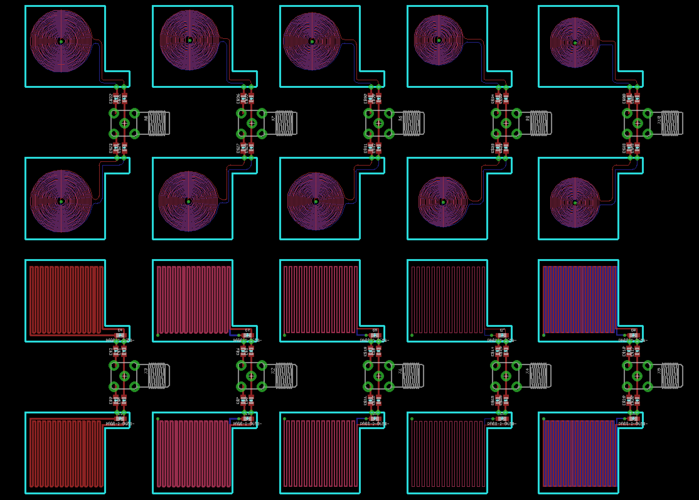
The meander coils did not produce any satisfactory results compared to the coiled ones. The coil inductors performed really well and we were able to vary various parameters to control the inductance quite accurately.
To draw these inductors in Eagle we used the spiral-coil.ulp with an 8mil trace width and 8mil spacing. Note: HQPCB can only do 8mil coils or more, while JLCPCB can do 6mil.
Performance
Going back to our original tests, subjecting the new inductors into rising temperatures (110C / 230F), resulted in a change of 0.2uH instead of the original 2.5uH at a 10uH nominal inductance. That is a drop from 25% to 2%.
The coil to coil tolerance in a PCB order was less than 5% so PCB coils beat other wirewound inductors. However we do understand that when you start manufacturing, putting inductors on a big panel, will result in uneven etching that will increase the coil to coil variance.
Also, while PCB inductors are very cheap, some houses will charge a little extra when they see coils on the PCB. We dont know why, but the inductor PCBs had a 15usd cost extra when coils were present. This was only with some factories.
All in all we believe that PCB inductors are pretty decent alternative so super critical applications where accuracy is important.
For us, we ended up using wire wound inductors with a ceramic core from Coilcraft since we didnt want to depend on PCB factories, etchant strengths, etc to get the desired micro-henrys. Also Coilcraft offered to bin their inductors before putting them in a reel to give us less than 5% tolerance. Well done Coilcraft for customer service.
Results
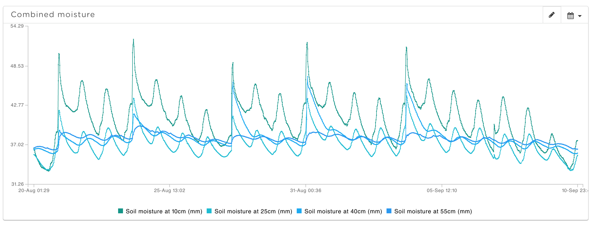
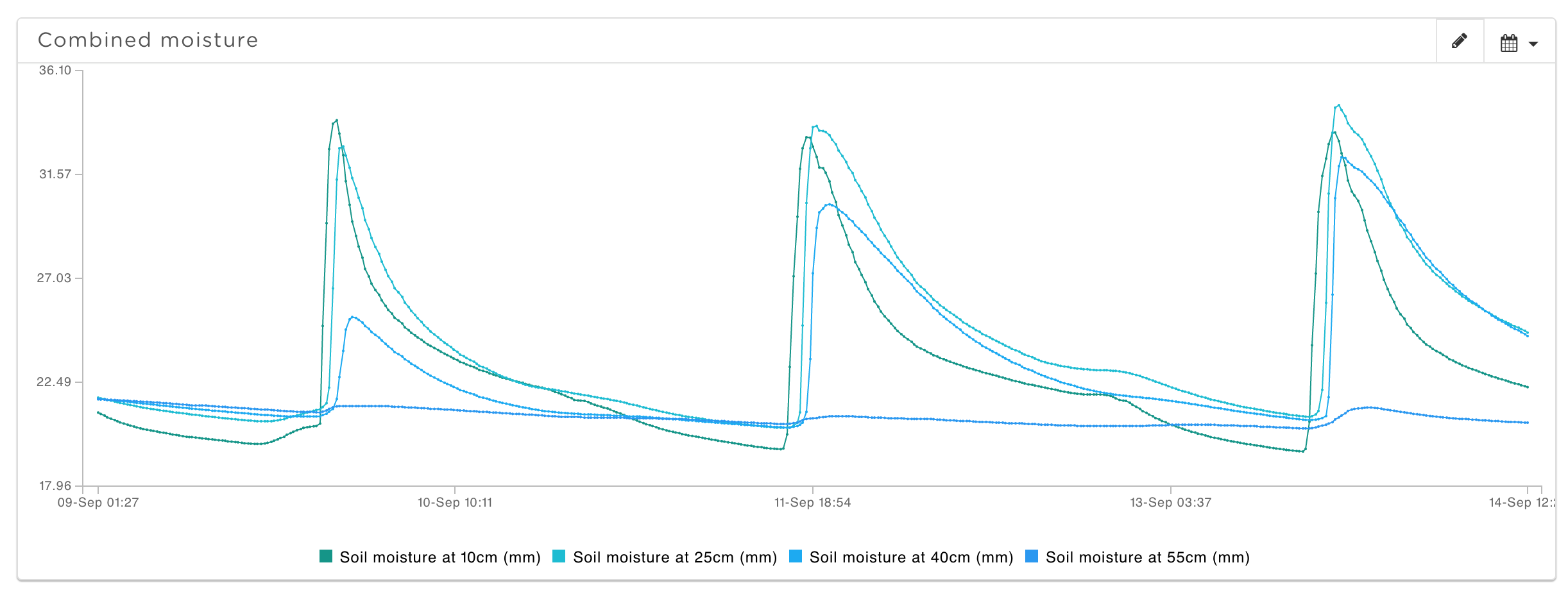
Below you can see the difference that PCB inductors and wirewound ones have over the multi layer ferrite ones. The large peaks are irrigation events and the rest are oscillations from temperature. Notice how a little inductor screws up everything.
This little article was part of our journey to make a soil probe for Pycno sensors (pycno.co)

 Costa
Costa
 Lithium ION
 SAYANTAN PAL
 Carl Bugeja
I've always been suspicious of inductors - so fussy to deal with. Looks like your findings are that PCB-trace inductors are the better choice, at least for your project. That's a pretty interesting result.
You might want to check out the work @Carl Bugeja does with PCB coils.