0%
0%
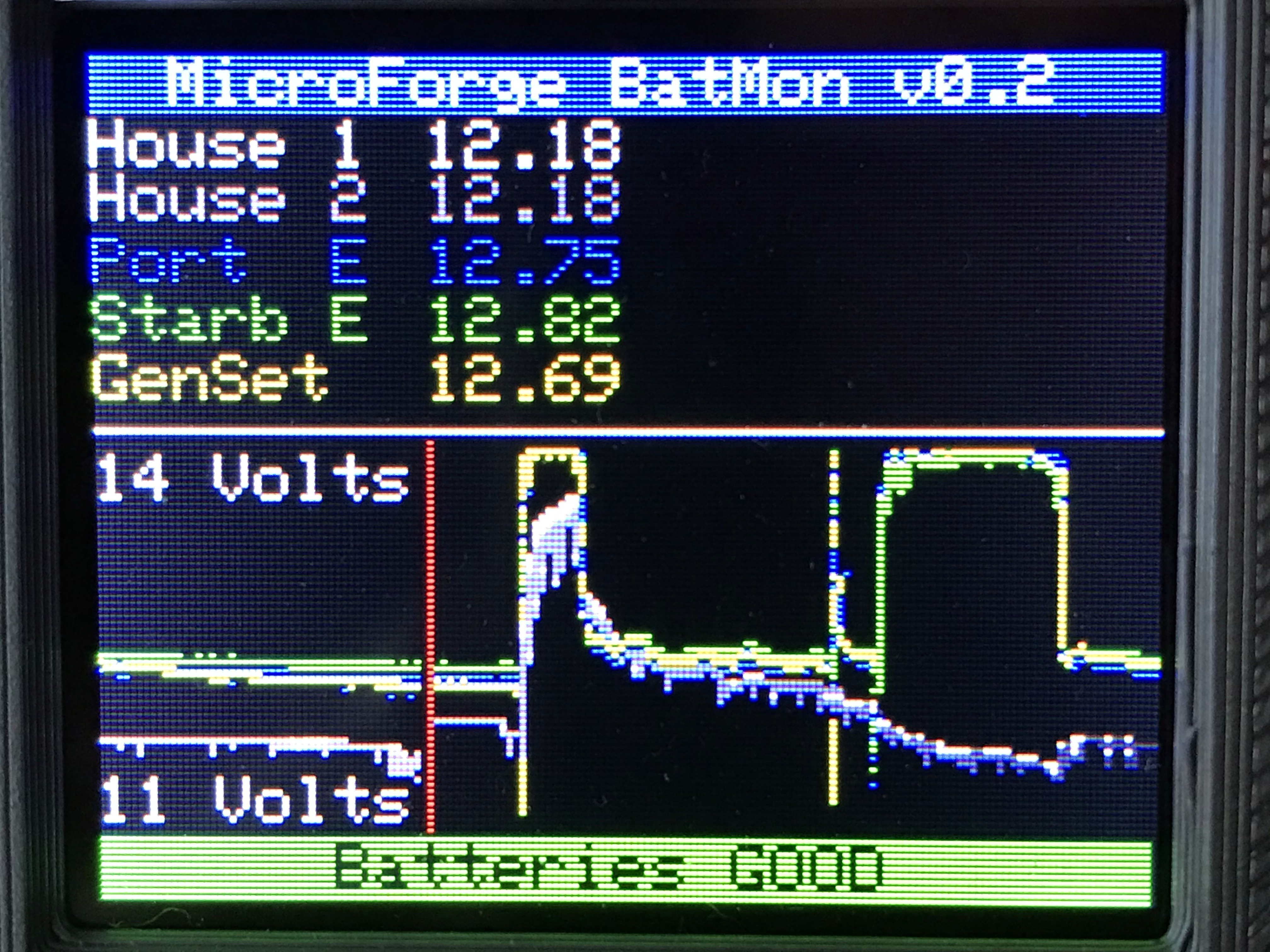
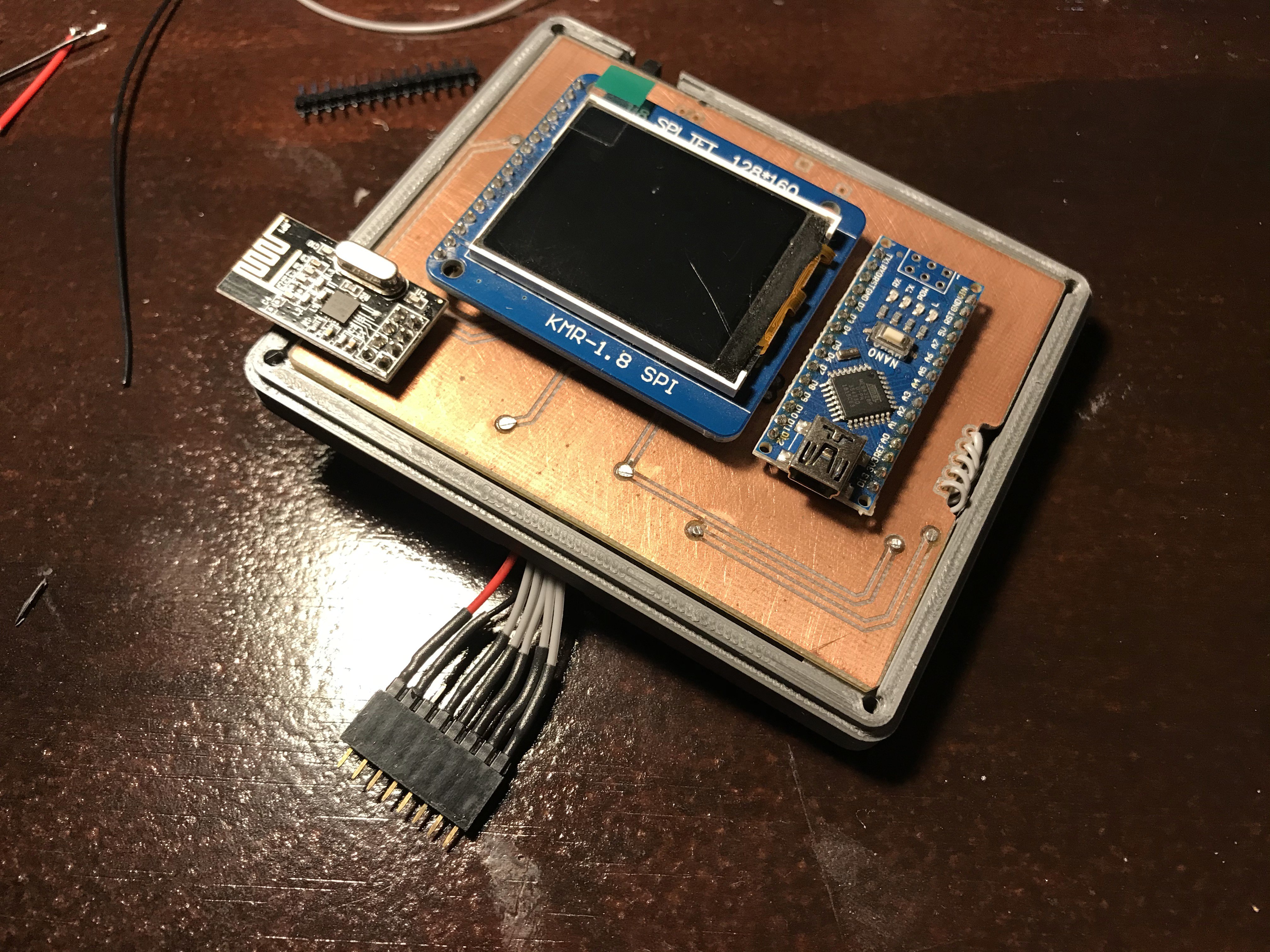
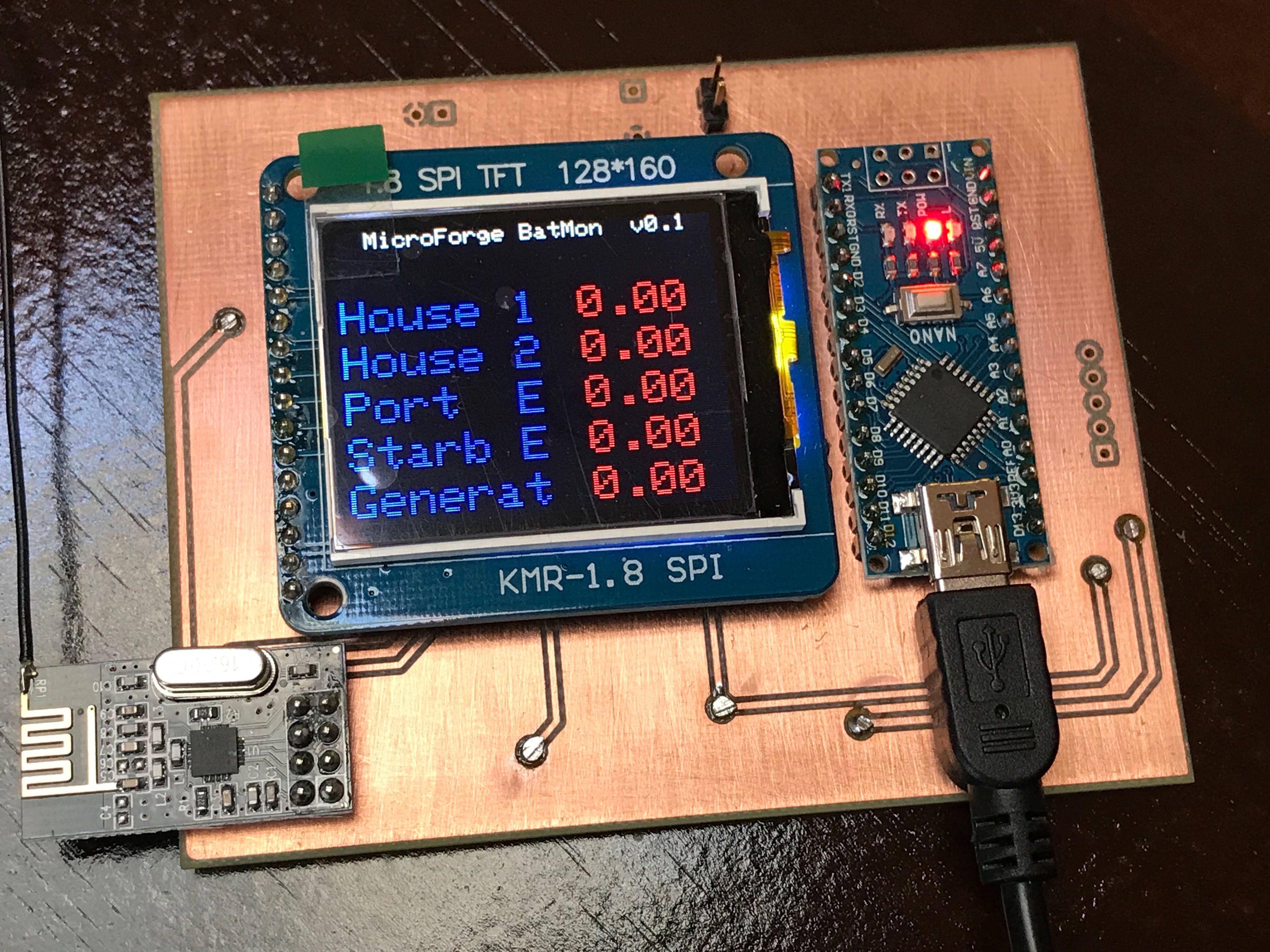
A Simple 5 Ch Boat Battery Monitor
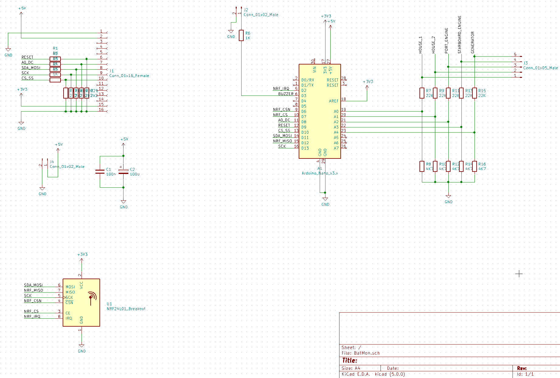
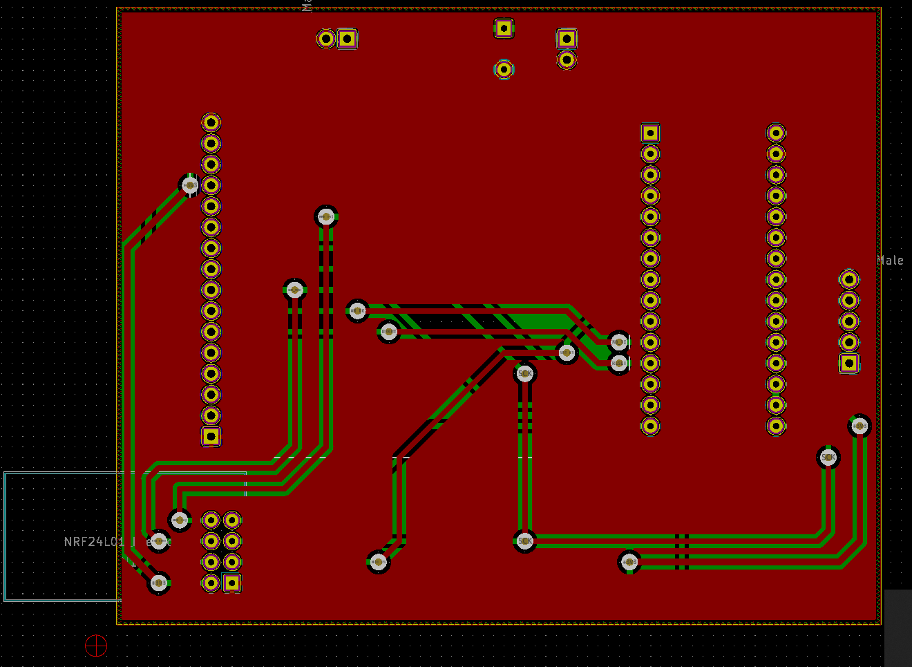
Five channel battery monitor with LCD status display and NRF24 Network wireless communication for marine and RV applications.
 Timo Birnschein
Become a Hackaday.io member
Already have an account? Log in.
Just one more thing
To make the experience fit your profile, pick a username and tell us what interests you.
Pick an awesome username
hackaday.io/
Your profile's URL: hackaday.io/username. Max 25 alphanumeric characters.
Pick a few interests
Projects that share your interests
People that share your interests


 Kevin Santo Cappuccio
 Jeff Cooper
 ipaq3115
 tiefpunkt
Hello Timo
Could you supply the Arduino code please?