 Damian Lickindorf
Detailed technical description:
(ax1 is the base rotation, ax2 the joint just above it, and so on...)
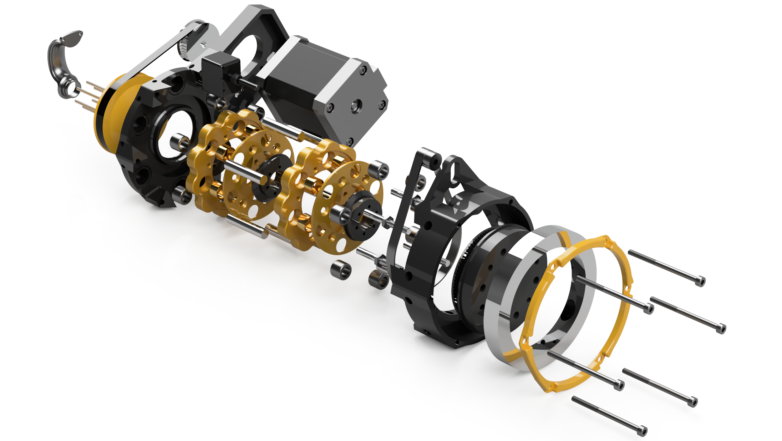
For control I use 5X Teensy 3.2 microcontrollers, they are connected together into a single CAN network, (Odrive is also on the same bus). Thanks to that I’m running just 5 cables through the entire thing - one for ground, one for 48V, one for 12v, and two for CAN. Ax2 - Odrive driven BLDC, 2step reduction - 1:5 belt + 1:24 cycloidal, so 1:120,
Ax3- Odrive driven BLDC, 2step reduction - 1:4 belt + 1:21 cycloidal, so 1:84,
Two encoders per axis for ax2 and 3. One encoder directly on the motor shaft, 8192PPR, used by the Odrive, and another one, 4096PPR on the joint driven by a dedicated belt(by 'dedicated belt' I mean one that has no load on it, and is used only to transmit rotation from the reducer output to the encoder - this increases precision in comparison to a belt that would be shared between and encoder and a motor) that is , giving 20480PPR for ax2 and 16384 for ax3 (1:5 for ax2; 1:4 for ax3). These ‘on joint’ encoders for ax2 and ax3 are connected to a single teensy, that's running two separate P loops - one for each axis, the output of these two P loops are two velocity commands for the Odrive. These are sent via CAN.
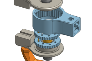
Ax4, 5, 6 - long nema17 steppers, also 2 step reduction, 1:2 belt (adjustable between 1:1 and 1:5 if needed) plus 1:11 cycloidal, so 1:22 total. The reducer I’m using here will be open source, it'll be called OpenCyRe. Each of these 3 wrist axis have their own encoder, driven by a dedicated belt, from the cycloidal gearbox output. The belt increaser is 1:5.25, the encoder is 512PPR, so the resolution of the joint rotation is 2688 for ax4, 5, and 6. Ax5 and ax6 run on the same teensy, and ax4 has its own teensy. That’s because the motor for ax5 and ax6 are not moving in relation to each other. The loop is again a simple P loop for all of these, the input is the ‘on joint’ encoder signal, the output is the frequency at which the stepper is making steps.
Ax1, single step 1:10 belt reduction, Nema 23 stepper motor, the encoder is a 1600PPR one, on a dedicated belt increaser (53:7) that increases the resolution to 11733 PPR
The 5th teensy is used in the pendant, the pendant has 2x 3axis joysticks, which allows control over all degrees of freedom. This teensy is also supposed to be connectable to the pc, allowing position commands to be sent via serial.
All axis are capable of 15RPM or more, the robot is capable of handling 2.5kg no problem, and up to 4,5kg if slowed down. The reach is 500mm. The positional repeatability is below 0.5 mm without changing the load, I haven't yet tested repeatability with vs. without load.


 Tim Wilkinson
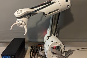
 Petar Crnjak
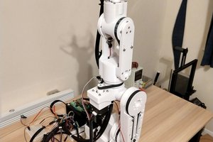
 Robin Fröjd
This looks Amazing! Keep going!