 bram
bram-
1Gather materials
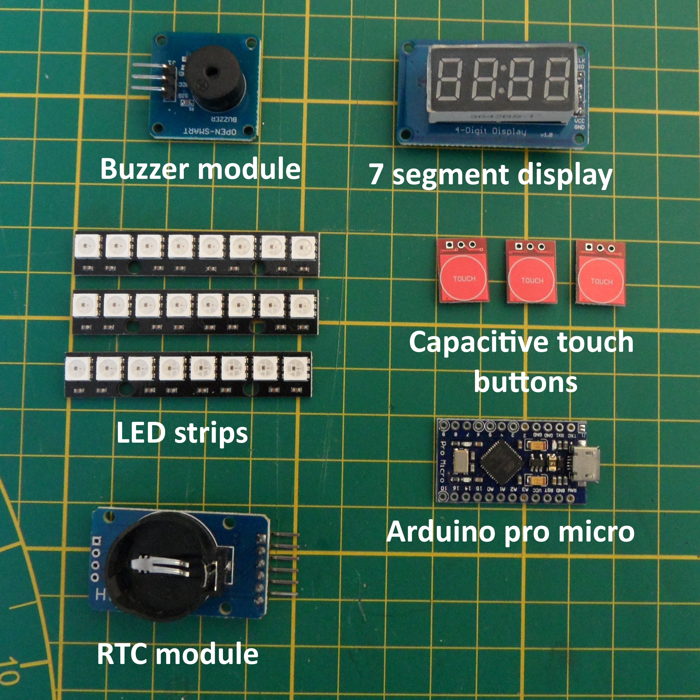
Start by gathering the materials for this build, the electronics can be found in the part list and the enclosure along the project files. Beside these parts you also need the tools and supplies listed below.
supplies:
- Superglue
- Wire
- Solder
- Small M2 screws
Tools:
- Wire stripper
- Soldering iron
- Screw driver
Electronics
![]() Enclosure
Enclosure![]()
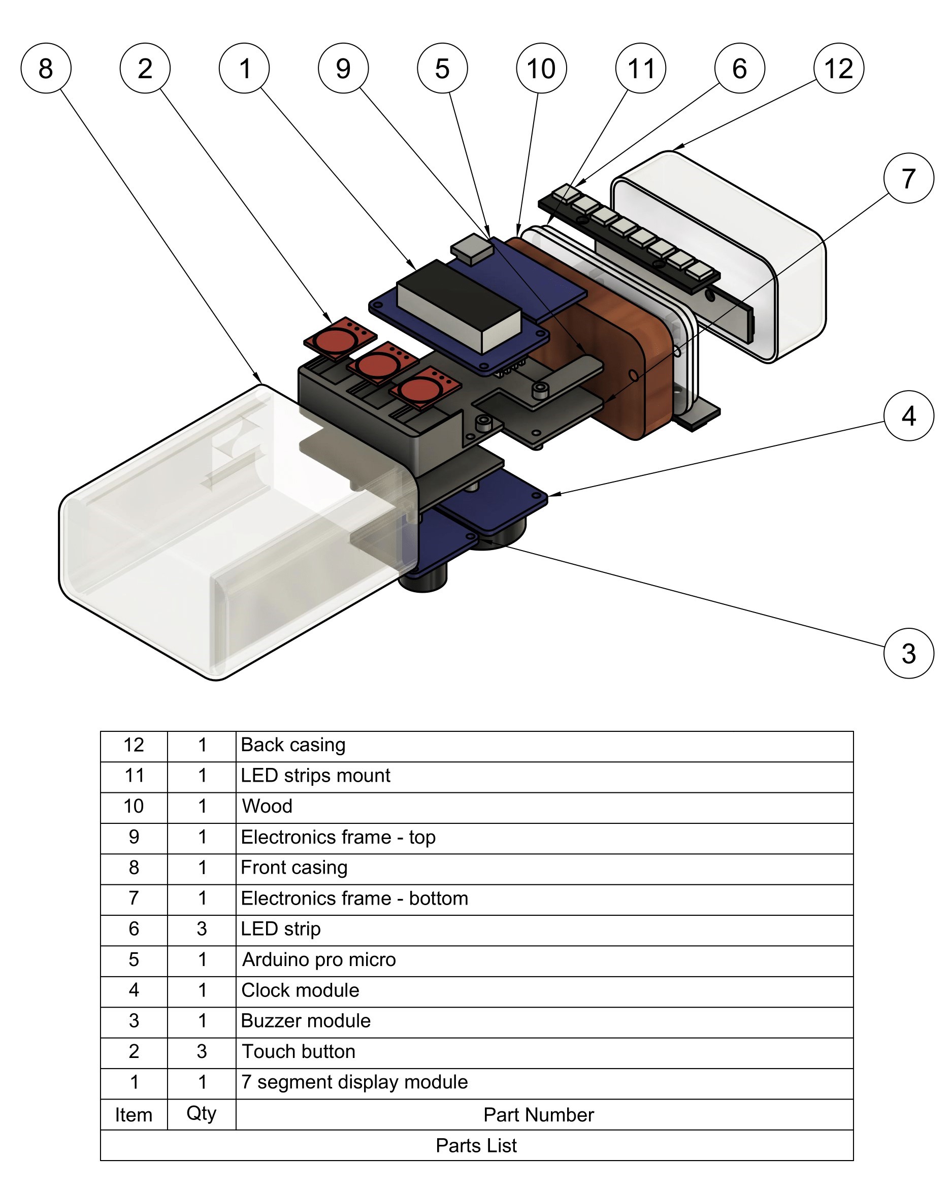
Assembly overview
![]()
-
2Wiring and programming the electronics
For this part, you need all electronic parts, the electronics top and bottom frame, and the LED strip mount.
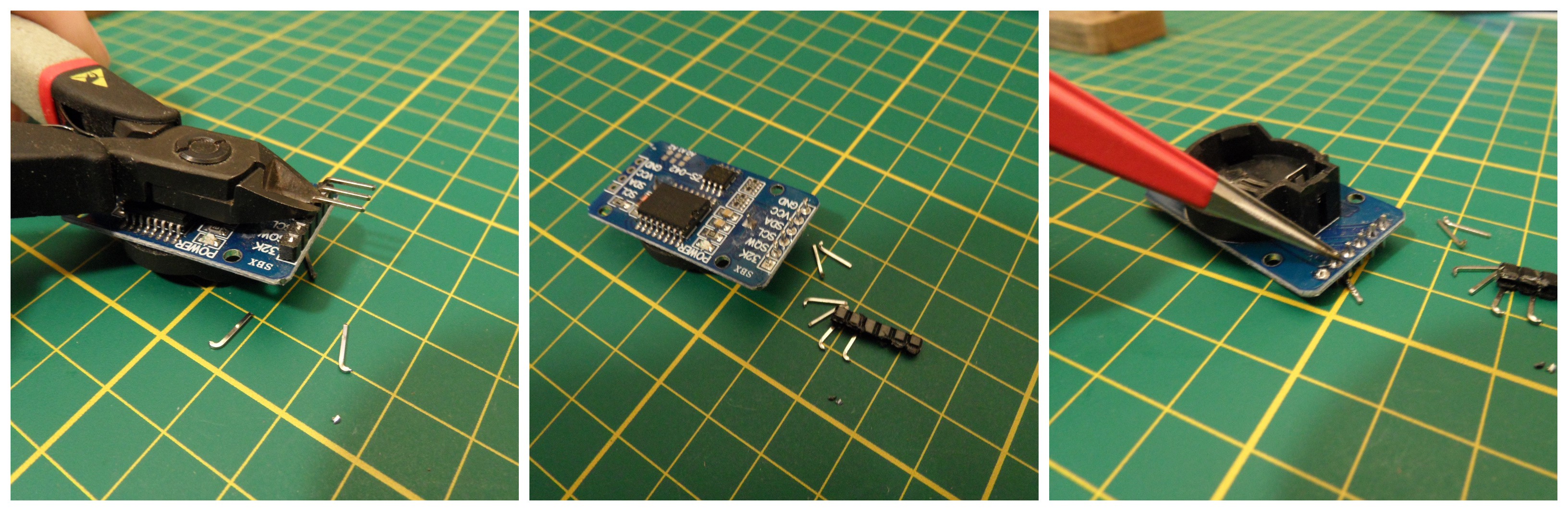
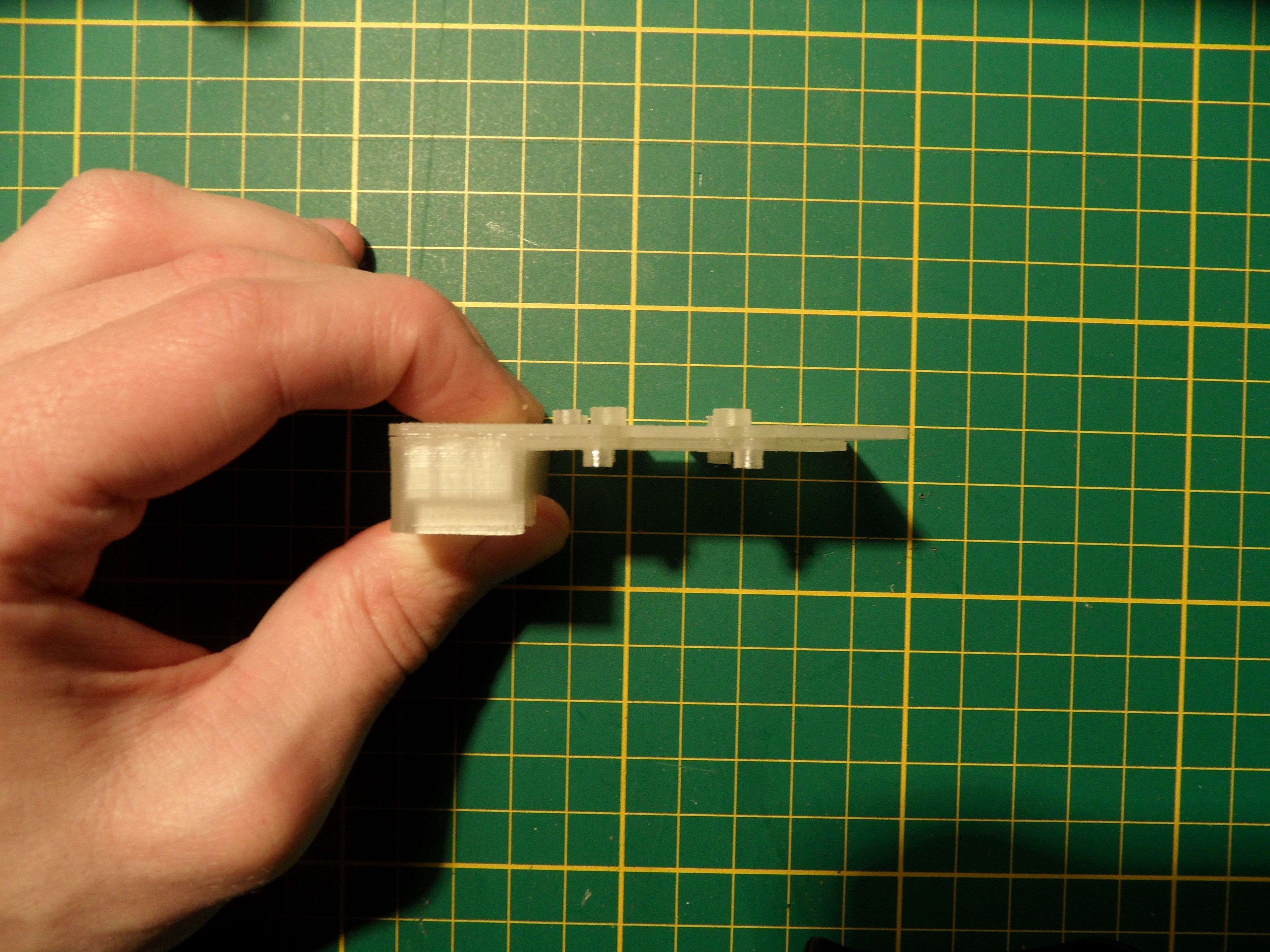
Start by removing the headers from all electronics modules. This step is needed to make sure there is enough room for the electronics inside the case. The easiest way to do this is to cut off all pins up to the black plastic and removing the plastic, this makes it easy to heat every individual pin and taking them out using tweezers.
![]()
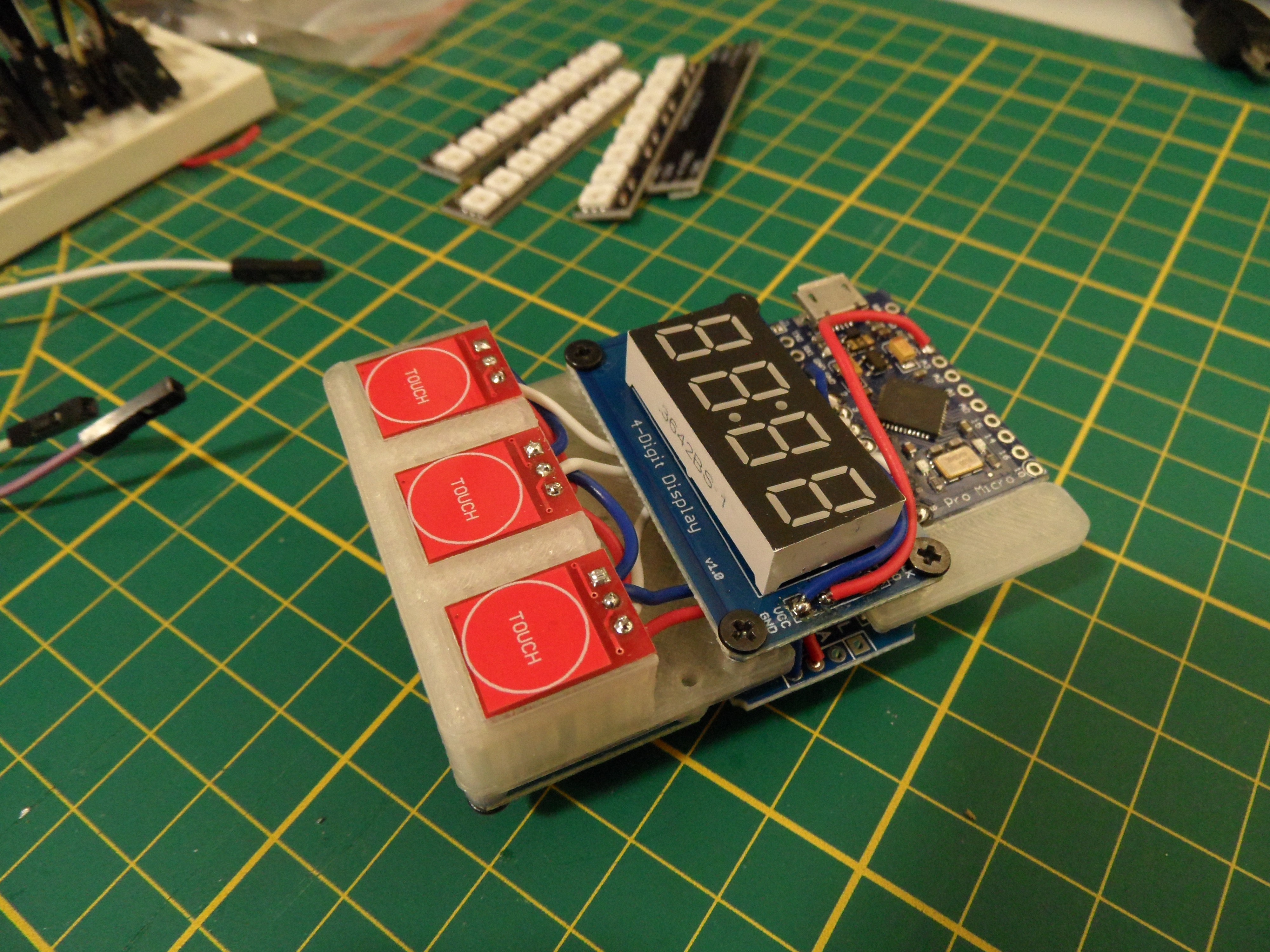
Next up we glue the top and bottom electronics frame together using some superglue and mount the electronics using some 4mm M2 glues (check the assembly overview for the mounting locations).![]()
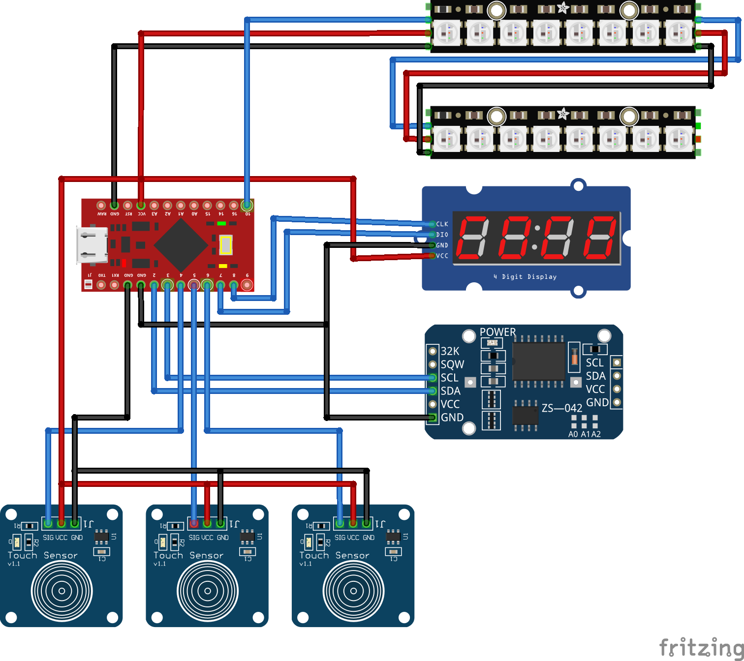
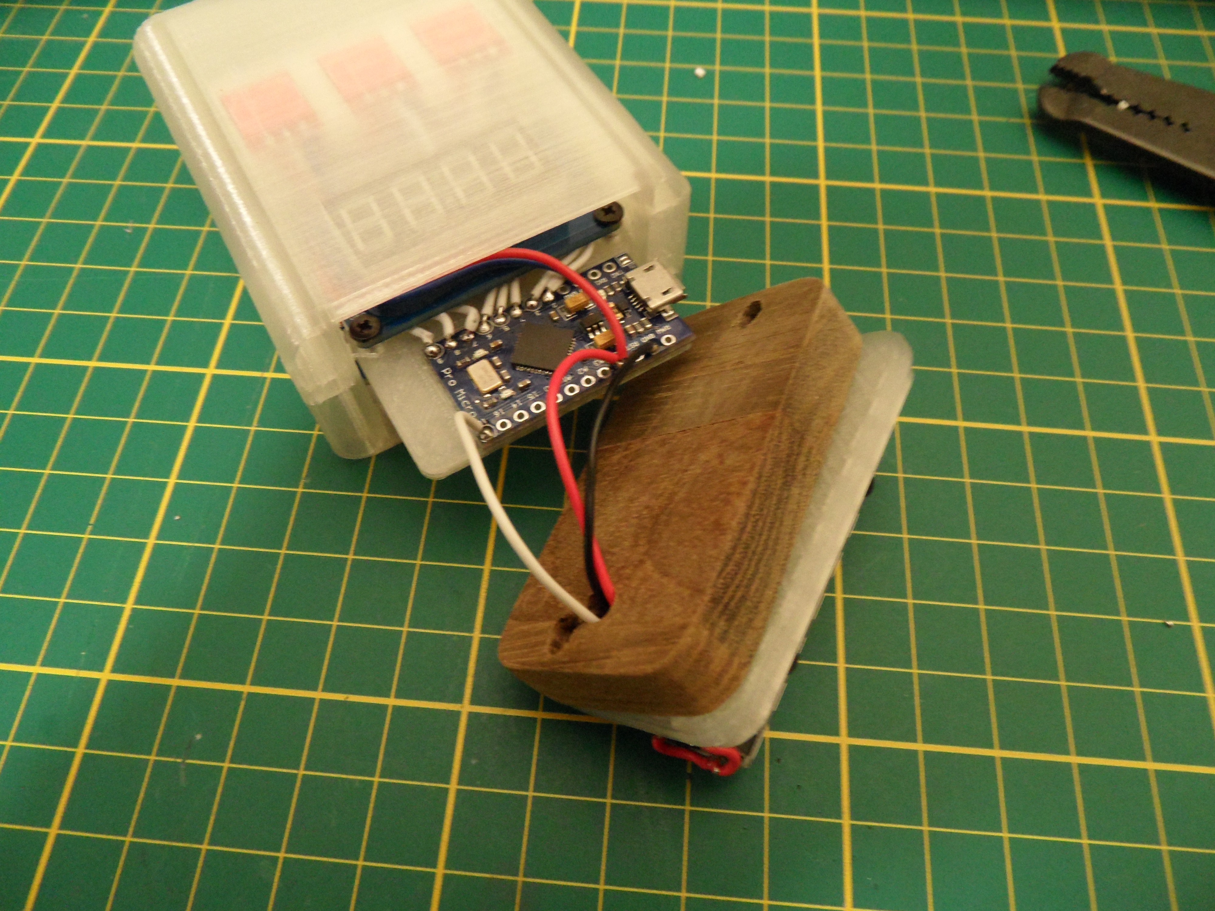
When all electronics are mounted to the frame we can start wiring the electronics using the schematics below. I've looped the power and ground because there is only one power pin available on the Arduino pro micro.![]()
![]()
-
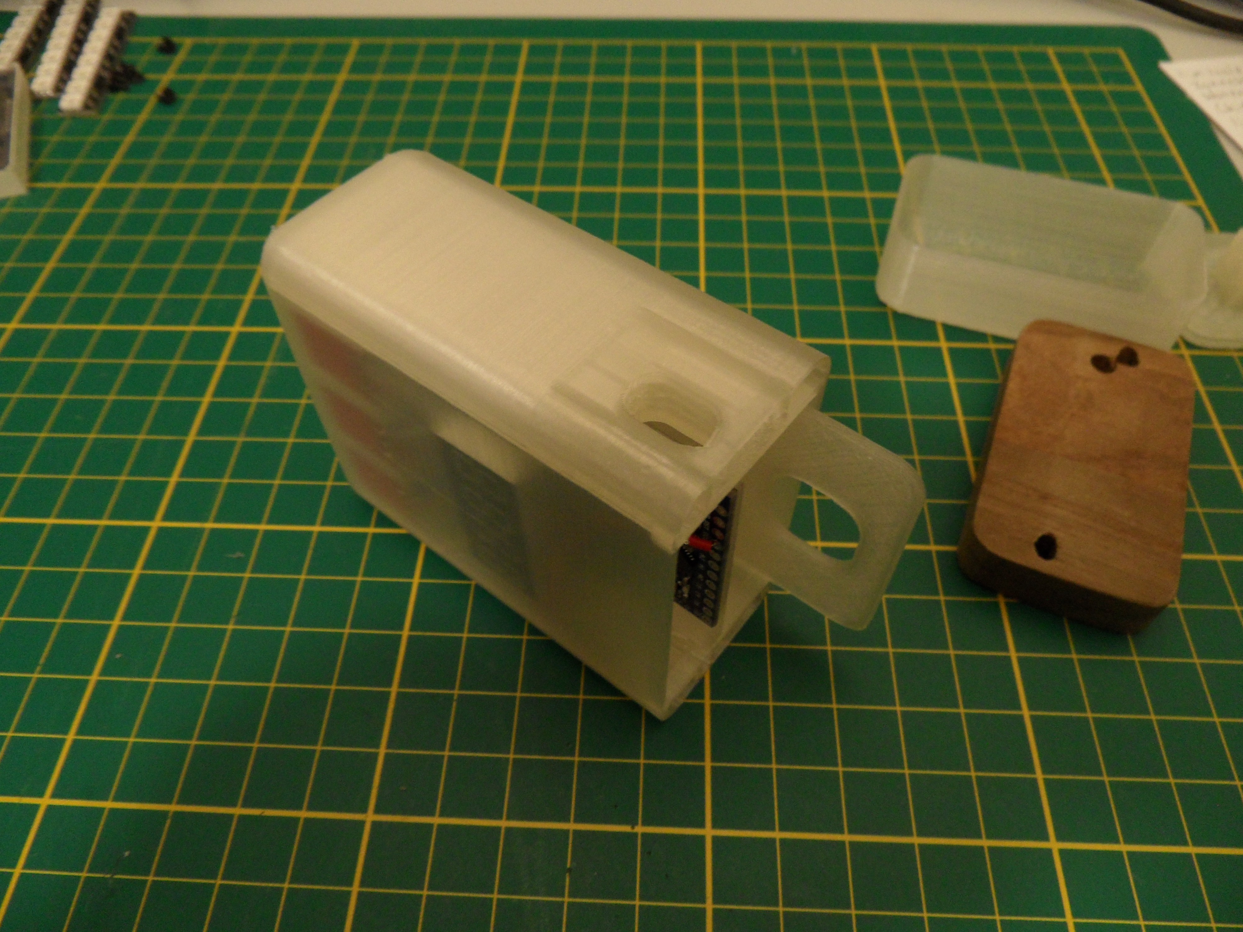
3Assemble the enclosure
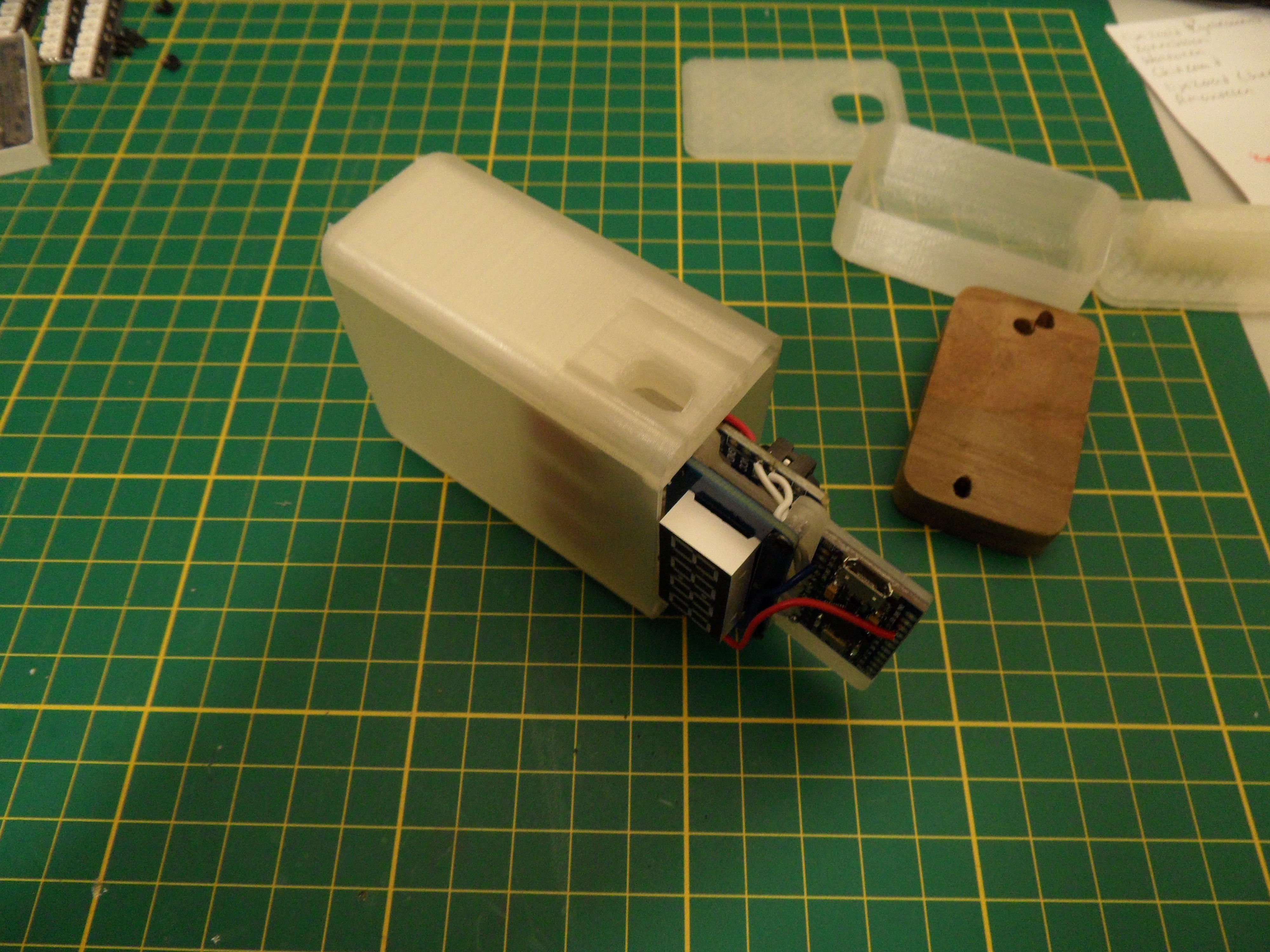
Insert the electronics assembly into the front enclosure.
![]()
Add the electronic securing tool
![]() Prepare the LEDS mounted on the mounting plate
Prepare the LEDS mounted on the mounting plate![]()
Solder the LEDs to the Arduino![]() Take of the LEDs and screw in the mounting plate
Take of the LEDs and screw in the mounting plate![]() Re-attach the LEDs and put on the back cover
Re-attach the LEDs and put on the back cover![]()
Wake-up light
A wake-up light is a simple alarm clock that simulates a sunrise to let you wake up more gradually than an alarm.
 Enclosure
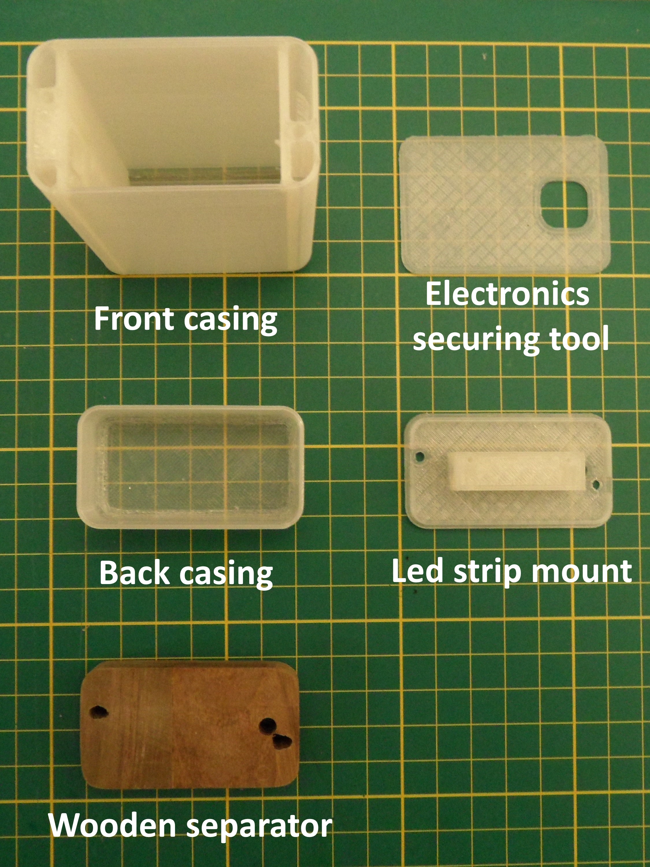
 Prepare the LEDS mounted on the mounting plate
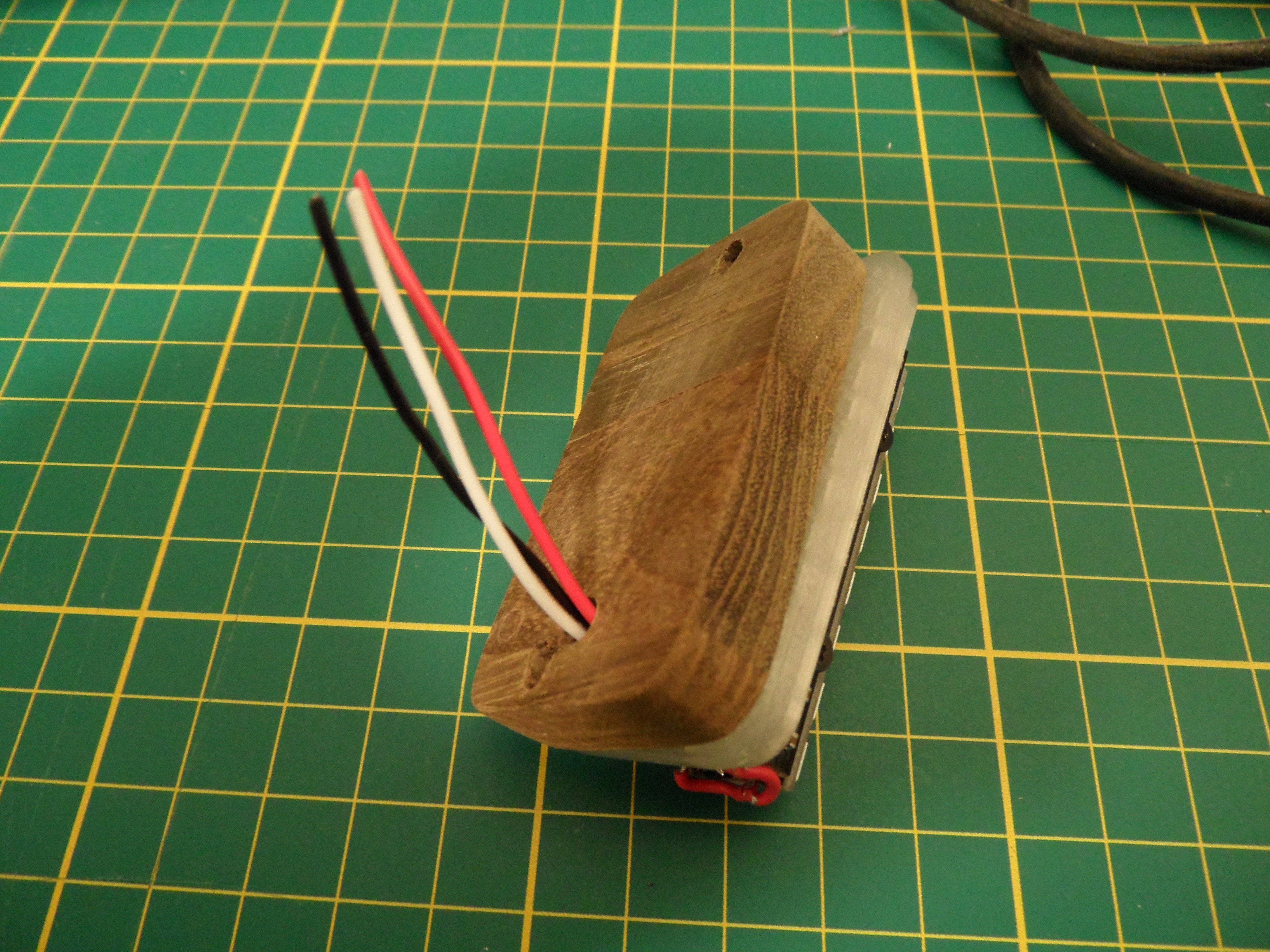
 Take of the LEDs and screw in the mounting plate
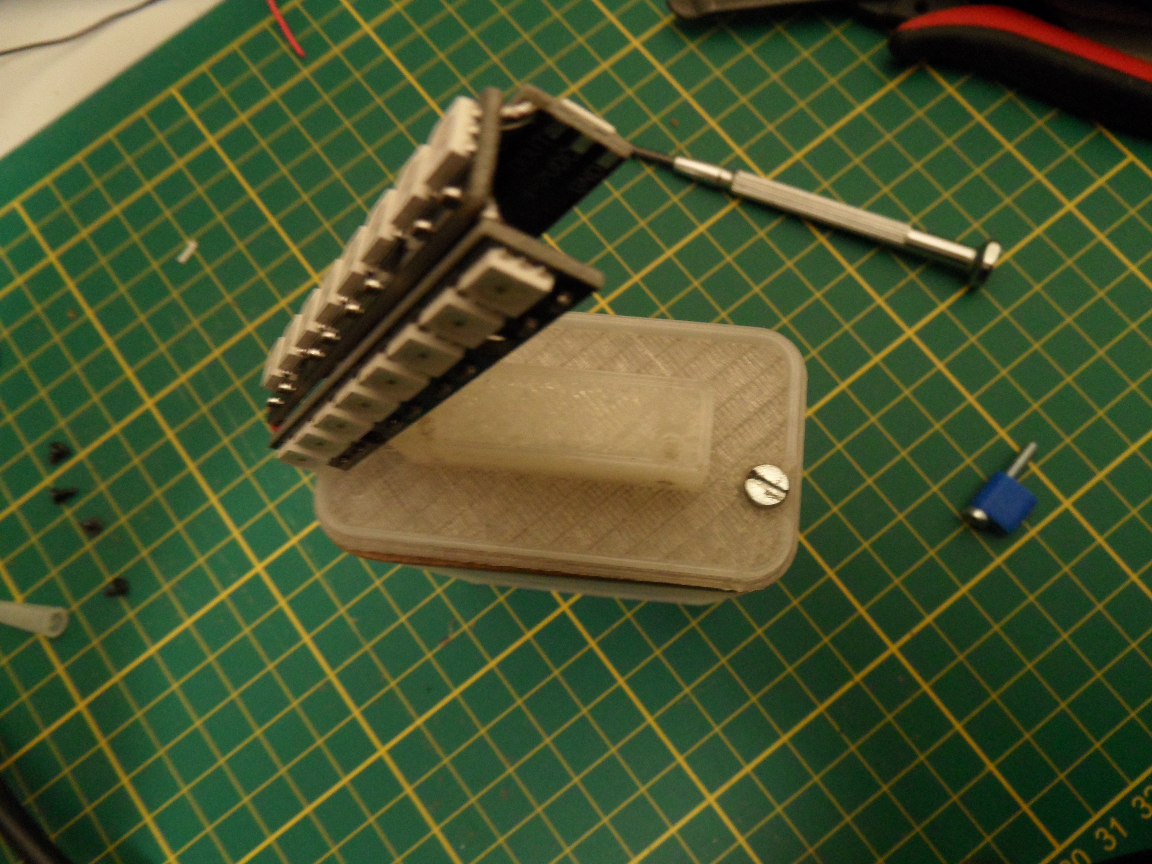 Re-attach the LEDs and put on the back cover
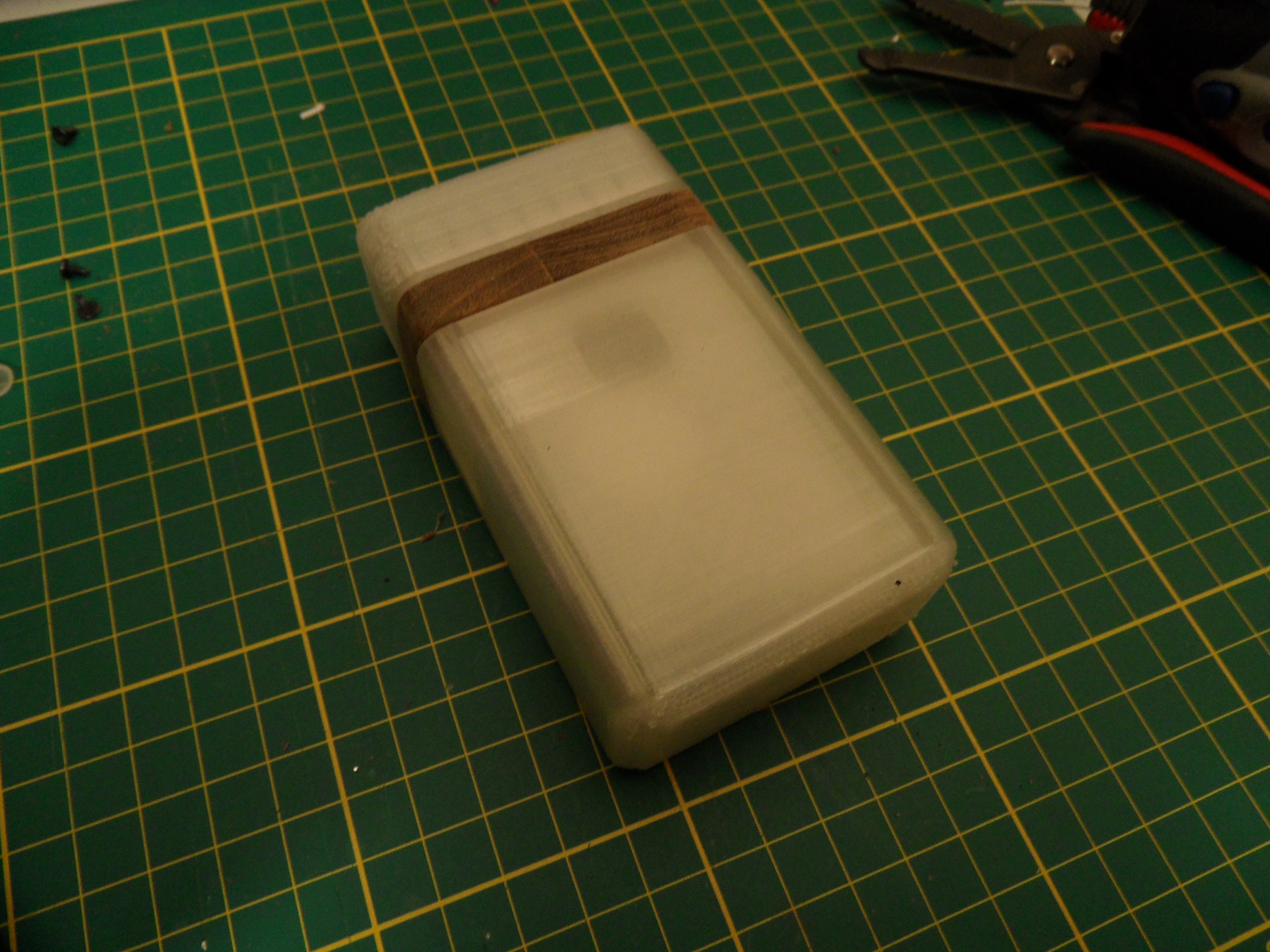
Discussions
Become a Hackaday.io Member
Create an account to leave a comment. Already have an account? Log In.