 Christoph Tack
Brightness
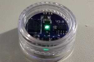
The luminance of the LED is 0.35 to 0.55 cd/m², measured with a Sekonic L-758CINE light meter. According to Wikipedia, this is about 10x brighter than the Phosphorescent markings on a watch dial after 1 h in the dark.
On the pictures you can see how bright the LED is. It's not easy to make pictures that give a good impression how bright the LED is at night.
This is bright enough to find your keys if you dropped them in pitch darkness, or to check on your baby without waking it. 1 cm high characters on a newspaper can be read without much difficulty. However, there's hardly enough light to read the newspaper's small print.
Implementation
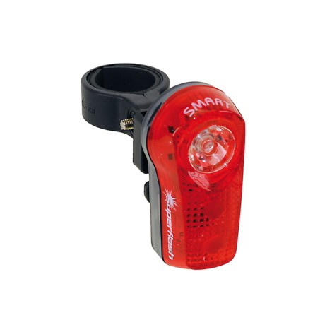
The #TritiLED project did a wonderful job in over-engineering a faint light. The current consumption is in the single micro-amp range, depending on the revision and of the current settings.
This is the challenge : "Can we build a light that consumes even less current?"
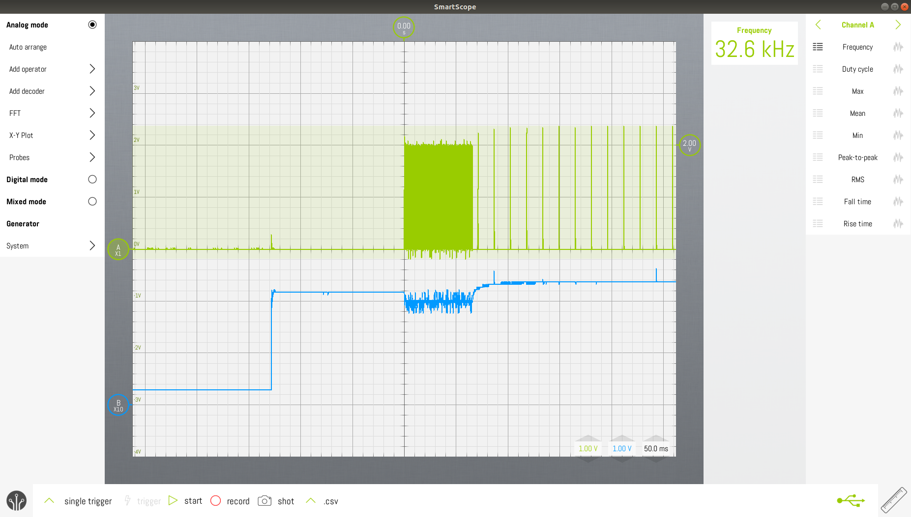
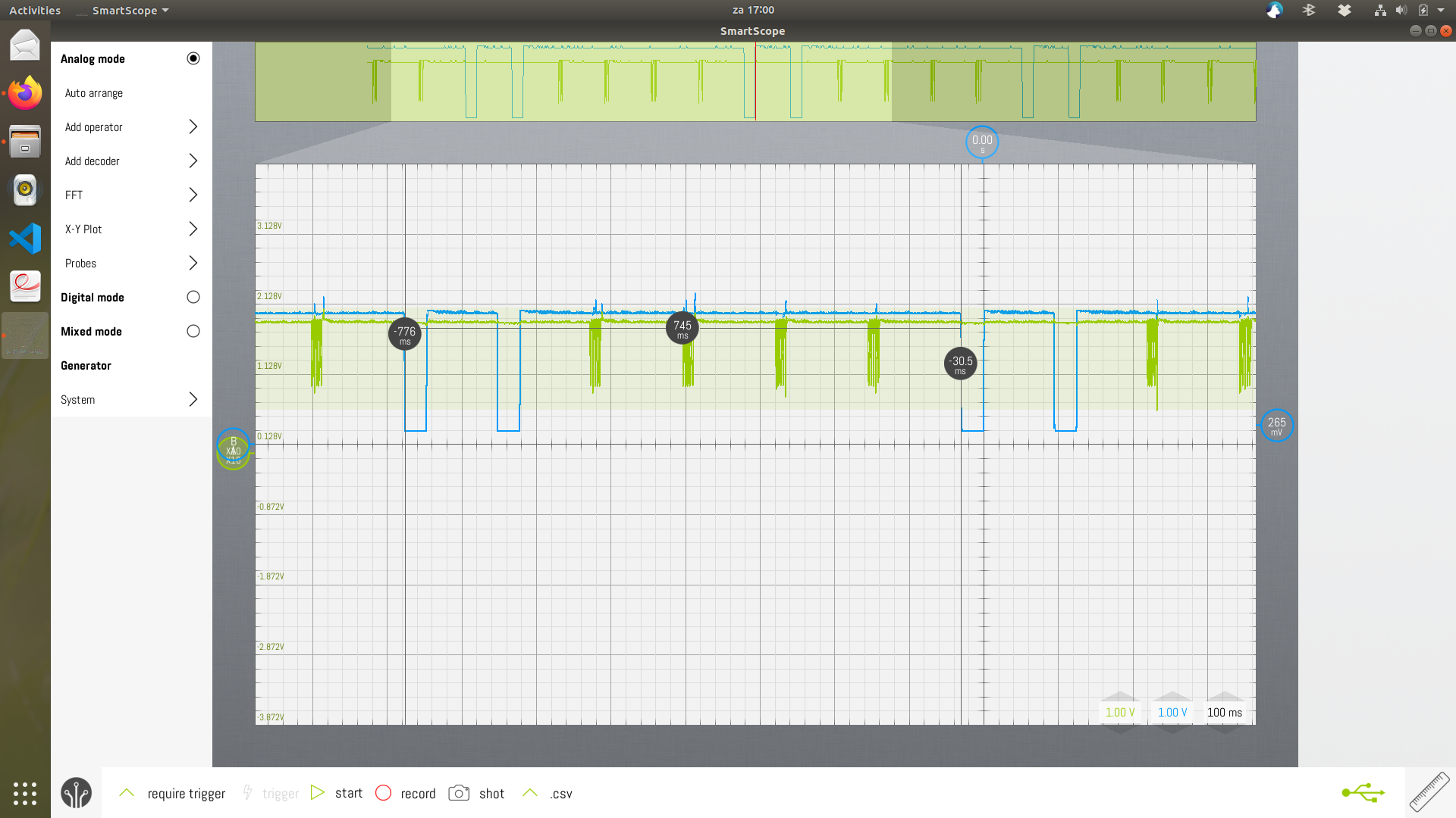
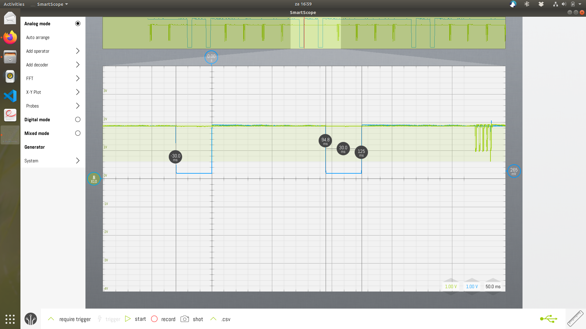
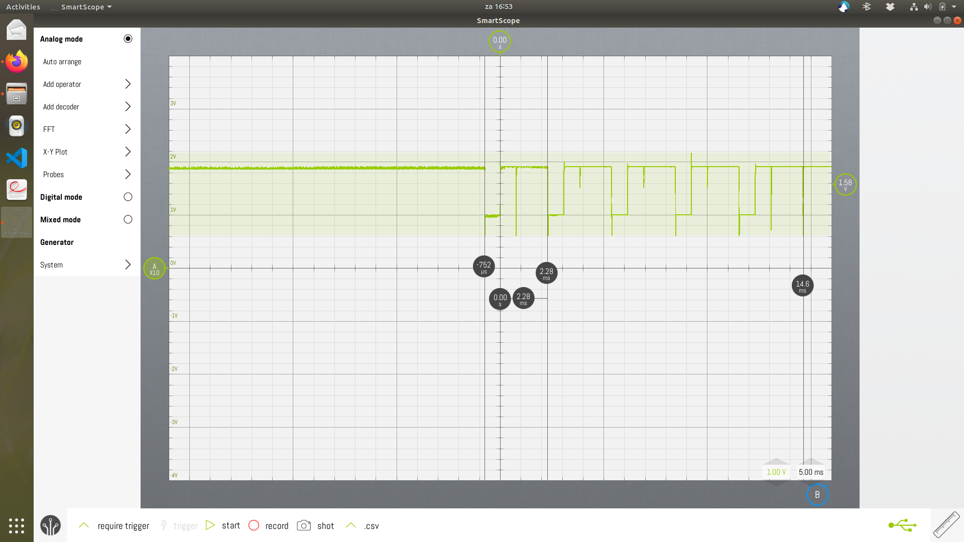
Update : July 10 2020 : 1.36µA on a 3V power supply (1 LED, 3µs pulse width, 64Hz repetition rate).
Building blocks
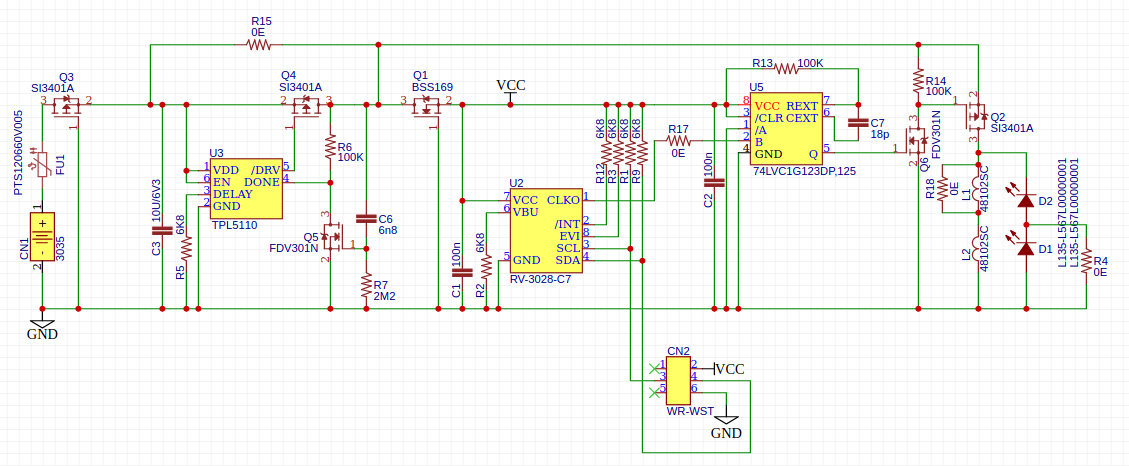
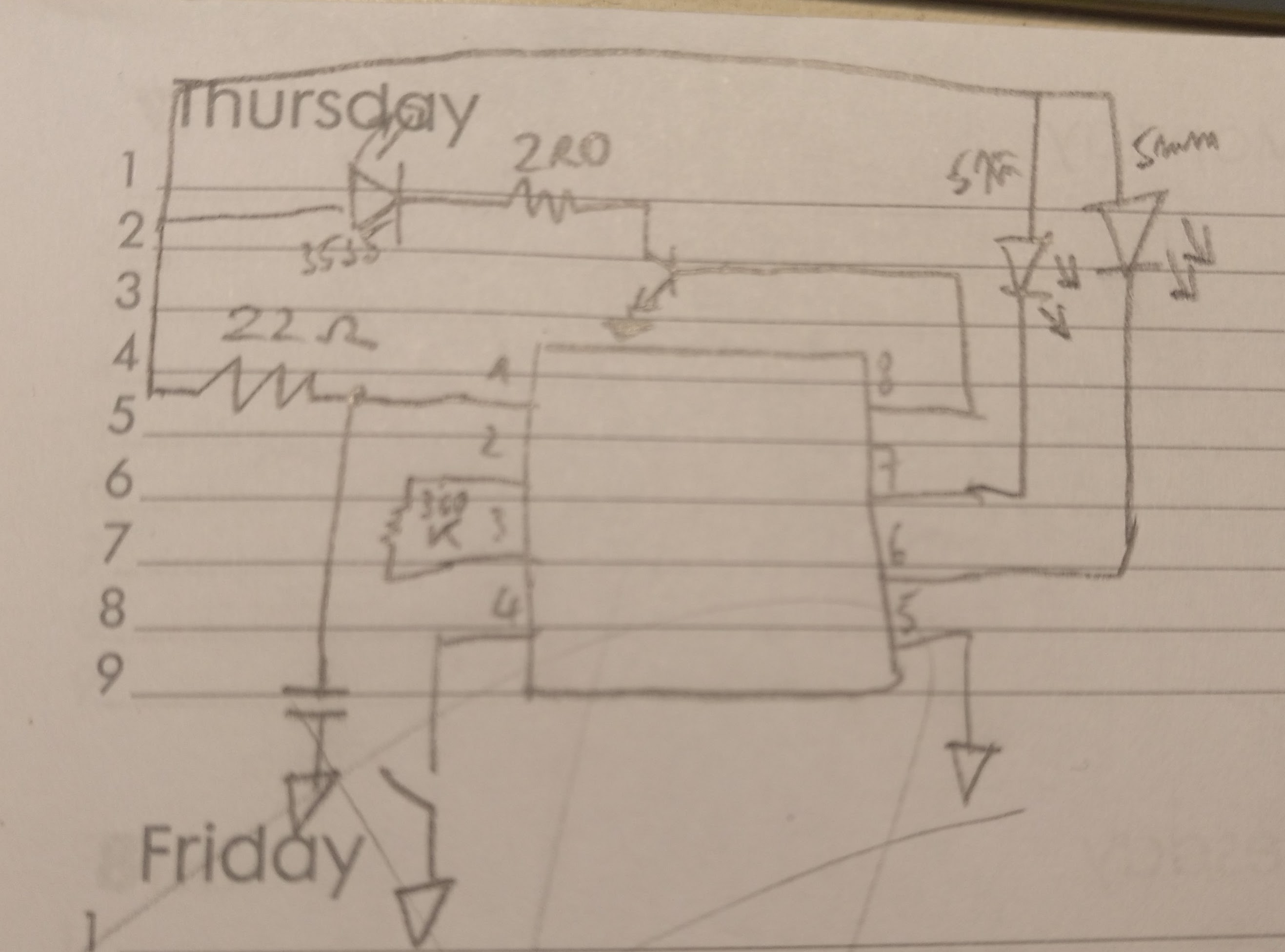
The design consists of a power source, optional ambient light switch, optional timer, some kind of oscillator, a one-shot timer, a LED-driver and an LED. The circuitry will be mounted in a housing.
Let's discuss these blocks a little more in detail
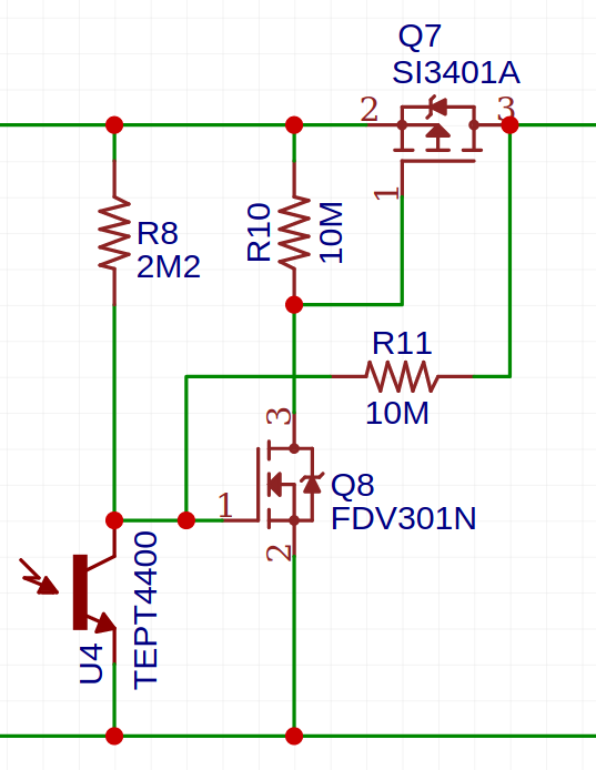
The ambient light switch has not found it's way to the schematic. Adding it would only have saved a marginal amount of current.
You might wonder why a one-shot timer is needed, when you already have an oscillator. It's only a matter of setting the desired duty cycle, right? The problem is that the oscillator runs at 64Hz, while the needed output pulse width is 3µs. That's a duty cycle of 0.0192%. While it's not impossible to make such a precision oscillator (a micro controller can do this easily), it's hard to make one that is low power at the same time. That's why in this design, generating the micro-second pulses is left up to the one-shot timer.


 Ted Yapo
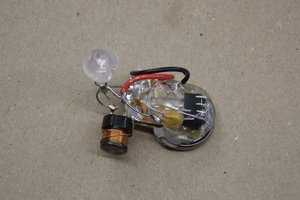
 Elliot Williams
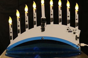
 Glenn.Kubota (gee.k)
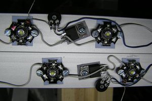
 Yann Guidon / YGDES
Since you presumably don't need the 1ppm accuracy, you could use the Ambiq AM0805 or Abracon AB0805, which use 16nA for RC operation. As far as I can tell, these and the RV-3028-C7 have a similar internal circuit, the A*0805 just don't have an integrated crystal and are therefore cheaper. Of course you can connect an external crystal, but then you might as well use the RV-3028-C7.
But the Micro Crystal part somehow has an even lower consumption with 45nA @3V instead of 55nA for the A*0805 (with XTAL). I wonder what they're doing differently...
Another very similar part is EM3028 by EM Microelectronic-Marin.
#Nanosleeper - Sub 100nA Sleep Dev Board is another project which uses the same RTC.