 Christoph Tack
-
Analog design IQ
05/24/2021 at 18:52 • 0 commentsPassive components
RF Attenuators
Inductors
- Measure inductance and capacitiance values with VNA: 3 methods depending on impedance
- Measure inductor saturation current
- Transformer saturation current can also be measured by applying DC-current to the primary winding, in series with an HF-decoupling inductor (many times the value of the inductor you want to measure and it should also have many times the saturation current). Then you can connect an L-meter to the secondary winding and start measuring.
Capacitors
- Measure capacitance value with DC-offset : Ceramic Capacitor with DC bias value measurement. LCR Meter
-
LoRa
02/20/2021 at 15:53 • 0 commentsLoRa
Why LoRa?
Gray coding, data whitening, interleaving, forward error correcting is all done in the transceiver chip.
- CSS (Chirp Spread Spectrum) :
- Resilience to interference
- Performance at low power
- Resistance to multi-path fading
- Resistance to Doppler effect
- Easy to decode, so can also easily be done on lower power simple devices.
- Gray coding : adds error tolerance
- Data whitening : induces randomness
- removing DC-bias in data
- long bit runs become less likely
- Whitening tends to distribute the data evenly across the radio channel’s frequency bandwidth, allowing the transmitter to run at a higher power without violating FCC regulations.
- Helps receiver synchronization
- Interleaving : Shuffling bits in a frame : reduces the impact of burst errors
- Forward Error Correction : Hamming codes
- 433MHz : less Free Space Path Loss (FSPL) than 868MHz.
- Actually as we're on earth and not in free space, we should use the MPPL instead which takes into account the Fresnel zone due to the reflections of the earth. The losses then increase with the 4th power of the distance.
- maximum effective bit-rate : 37.5kbps
- 256 byte FIFO, shared for RX & TX
- Critical parameters:
- spreading factor (SF):
- Each step up in SF means doubling of air time (i.e. bitrate/2). There's always one symbol per chirp. So increasing SF means lowering the chirp rate.
- Each step up in SF means an extra bit per symbol (e.g. SF7 = 7bit per symbol)
- Each step up in SF correlates to about 2.5dB extra link budget
- TTN uses Adaptive Data Rate (ADR) to use bandwidth and power more efficiently.
- modulation bandwidth
- higher bandwidth has the disadvantage of higher noise floor
- error coding rate
- spreading factor (SF):
Why not LoRa?
The maximum effective bit rate according to the SX1276 datasheet is 37.5kbps, which is done at 500kHz BW, SF6.
Where is that legally possible (ETSI EN 300 220-2 V3.2.1 (2018-06), Annex B)?- Band H : 433,050 MHz to 434,790 MHz, but with following limitations: ERP = 10mW, duty cycle = 10%. That leaves you 3.75kbps at 10mW.
All other bands are either too narrow, have even more stringent limits on duty cycle or have stricter power limitations.
Air time calculation : The fastest possible is SF7 with 250kHz bandwidth and a packet size of 120bytes. Aside from the thought that such a large frame size might not be a good idea, this results to 100ms air time per packet, which is corresponds to the maximum duty cycle of 10%. So we could send 120bytes/s = 960bits/s. We could also send two 50ms air-time packets per second, but these would contain only 50 bytes each.
LoRa module
Modules with integrated MCU
- Seeed LORA-E5
- RAK Wireless RAK3172 (comparable to LORA-E5), RAK4260, RAK4270
Low power, low cost modules
- Ai-Thinker Ra-02 (LCSC C90039)
- NiceRF LORA1278-C1
- RFM96/RFM98 Seeed 109990165
- RFM96W-433S2 : no longer available as module (except AliExpress etc.)
- RFM98W-433S2
- Difference with RFM96W-433S2 unclear
High power modules
NiceRF
- NiceRF LORA1268F30-433
- 33dBm
- works on 3V3 (max. 28dBm), needs 6VDC for 33dBm
- min. TX-pwr = 10dBm on 3V3.
- no coax-connector
- 38x20mm
- 5mA RX
- 2µA sleep
- LoRa RX-sensitivity (BW=62.5 KHz, SF = 12 CR=4/5) = -139dBm
-
NiceRF LORA1278F30-433- 30dBm
- 13mA RX
- 10µA sleep
- LoRa RX-sensitivity (BW=125 KHz, SF = 12 CR=4/5) = -139dBm
EByte
- E19-433M30S
- 3V3 to 5V
- 25x37mm
- 20mA RX
- 3µA sleep
- has u.fl-connector
- max. TX-power 29.5dBm
- LoRa RX-sensitivity figures unrealistic
- E22-400M30S
- 2V5 to 5V5
- 24x38.5mm
- 14mA RX
- 3µA sleep
- has u.fl-connector
- max. TX-power 21.5dBm
- LoRa RX-sensitivity figures unrealistic
HopeRF
- RFM98PW
- 5V to 6V
- 18x35mm
- 15mA RX
- 5µA sleep
- no coax connector
- max. TX-pwr=30dBm
- LoRa RX-sensitivity (SF12, BW=125kHz) = -136dBm
- Seeedstudio RFM98
- 2mm pitch, not breadboard friendly
- CSS (Chirp Spread Spectrum) :
-
70cm band Antennas
12/08/2020 at 20:20 • 0 commentsGeneral
Understanding Antenna Specifications and Operation : Application Note AN-00501
- The quarter wavelength on 433MHz is 17cm.
- VSWR < 2.0 is acceptable. Less than 10% of the power will be reflected back to the transmitter.
- Baluns avoid RF-radiation and noise pickup from the feed line:
- These baluns should be placed as close as possible to a balanced type antenna (feed point).
- Not needed for monopole antennas because they're unbalanced.
- FCC CFR Part 15 forbids standard connectors like SMA. RP-SMA is allowed.
- The frequency of lowest VSWR is not necessarily equal to a resonant frequency of the antenna.
- lowest VSWR = antenna impedance closest to 1 on Smith chart.
- resonance = antenna impedance is purely resistive, on X-axis on Smith chart.
Antenna testing
VSWR measurements on quarter wave monopole antennas don't mean much in reality. So the measurements below should be taken with a grain of salt.
The λ/4 monopole antenna performance strongly depends on the size and orientation of the ground plane and hand capacity etc...
An antenna with a good VSWR in a lab setup (using a large perpendicular ground plane) doesn't guarantee it will perform well in real life conditions, when it's connected to your HT.- It would be better to attach ferrite beads on the coax cable near the antenna. In case of unbalances, this will limit CM-current (less effect when coming closer with your hand, etc...)
- Real world antenna testing
- Testing Ham Radio HT Antennas (Signal Stick, Nagoya, Diamond)
- #188 Antenna Tutorial incl. cheap DIY Antenna Tester (LoRa, ESP32)
- Radio link budget calculator
- better to use a tool that calculates MPPL (multipath power loss, see theThingsNetwork) instead of free space losses
- 434MHz TX, 0dBi antenna, 0dB cable loss: 20dBm → 100m→ RX: -45dBm
- Doubling distance will lower received power with 6dB
Antenna tuning
- Monopole antennas must be used with a ground plane
- Use smith chart to find resonant frequency. That will be where the graph crosses the horizontal axis.
- Tune the length of the elements to get the impedance at the resonant frequency closer to 50ohm.
- If antenna tuning is not possible (because of a COTS-antenna), you can use a matching network to match your radio's impedance to the antenna impedance in an effort to get the VSWR < 2.0.
λ/4 Monopole antenna characteristics
- Zin = 36Ω at the resonance frequency (over an infinite ground plane)
- Maximum gain = 5.15dBi (3dB more than dipole antenna)
- The go-to antenna here is a ground plane antenne. The resonant frequency can easily be tuned by cutting the monopole, while the impedance can be tuned by folding the radials.
- Monopole antennas need a ground plane, so you shouldn't use them with a u.fl to SMA cable assembly. Dipole antennas can be used with u.fl-SMA cables.
- Monopole antennas can be used with edge soldered SMA-connectors.
- All 433MHz whip antennas on the market seem to be monopoles. I guess dipoles would make them too long.
AliExpress WirelessLink store PM433-ZB165BM (71A, 433MHz 16.5cm ZT SMA)
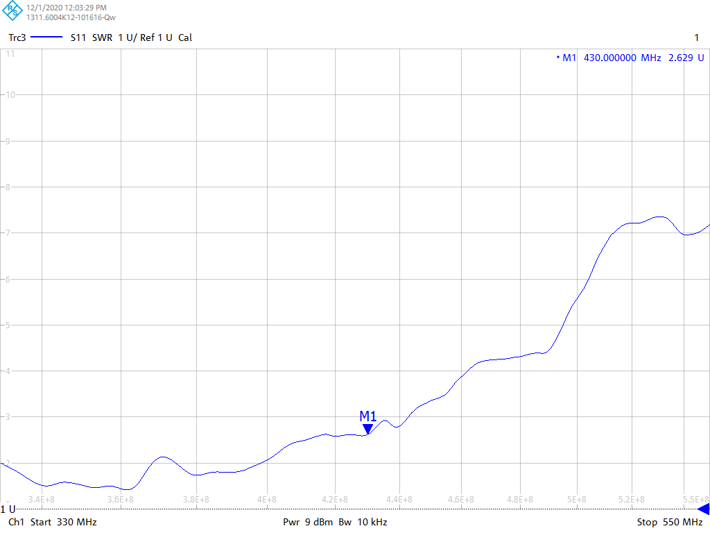
The characteristics have been measured with a direct connection to the VNA. No ground plane added. This will impact bandwidth as well as center frequency.
The default antenna frequency is by no means 433MHz, as can be seen in the first graph.
![]()
Wrong way of measuring ! : VSWR of antenna directly connected to VNA.(https://cdn.hackaday.io/images/5866921607457173224.png) Monopole antennas should always be measured with a reasonable size ground plane (radius > lambda/4).
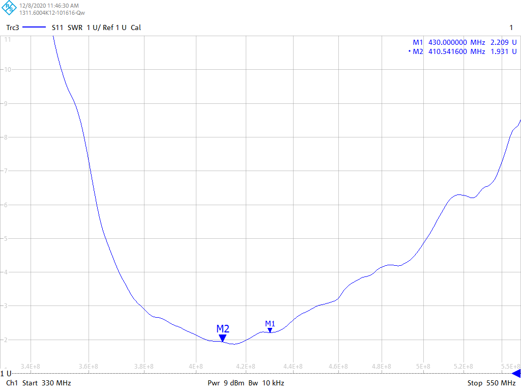
![]()
VSWR measurement of antenna on serving tray. This seems pretty good!(https://cdn.hackaday.io/images/8070311607457349499.png) Measurement on Smith chart with serving tray as gnd plane:
- Resonance: Z = 27 + 0j ohm at 408.3MHz
- Minimal VSWR: Z = 28.5 - 3.8j ohm at 404.9MHz
Measurement when SMA taped with Cu-tape to the edge of Al-GND plane (800x2000mm)
- Resonance: Z = 78 + 0j ohm at 417MHz
- Minimal VSWR: Z...
 SimpleTronic
 bobricius