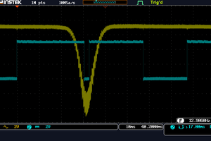
Hear for yourself: https://www.youtube.com/watch?v=Dde6-o0uda0
https://github.com/alberto-grl/1bitSDR
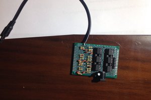
This project has been created as a way to learn Verilog and have some fun with FPGA and SDR. Main goal is to receive AM broadcast stations with as little components as possible. The FPGA chosen, Lattice MachXO2, is also among the simplest components that can be used. I was able, with 20 meters of electrical wire as an antenna, to receive stations from thousands of kilometers, located in three continents. Smallest BOM consists of a 30 euros Lattice MachXO2 breakout board, three resistors, one capacitor and a speaker. For better performance it is best to add a crystal oscillator, sensitivity and audio quality are better than with the internal oscillator.
The antenna is directly connected to an input pin, as you know static charges can damage the board. When you are tired of record-breaking component count it is better to add a series capacitor and two limiting diodes. Audio is more practical with an RC filter, a series capacitor and an active speaker.
The radio architecture is quite standard, a direct-conversion receiver. We have an ADC, a Mixer, two CIC filters for the quadrature signals, an AM demodulator which takes the square root of the sum of the squares of the signals, and a PWM for audio output. Frequency tuning is obtained by an NCO, a 64-bit accumulator whose increment is controlled by an UART, it is possible to send some characters from the controlling PC and change frequency. The board has a spare UART channel for this. Main channel is used for programming, it is necessary to connect the second channel of the USB-to-serial converter to the FPGA by soldering a bridge on the lower side of the board, see the documentation.
ADC uses an LVDS comparator as input, but it works differently than the Sigma-Delta converter like http://www.latticesemi.com/-/media/LatticeSemi/Documents/ReferenceDesigns/SZ2/FPGA-RD-02047-1-5-Simple-Sigma-Delta-ADC.ashx?document_id=35762
In that case the feedback signal tracks the input by using a low RC time costant. At radio frequencies this is impractical and the feedback is used to keep the comparator near the switching level by a large RC constant. Sampling is performed by the random RF noise superimposed to the desired signal. We are oversampling at 80 MHz a 6 KHz bandwith signal. A brief explanation for this: if the input is truly random its mean value over a certain time will be almost zero. But it is summed with a very small radio signal from a distant transmitter and this is enough to slightly influence the output. https://en.wikipedia.org/wiki/Oversampling
CIC filter decimation is 4096 so the theoretical increase in resolution of the ADC is 6 bit.
It would be better to have a lower CIC decimation followed by a FIR filter. It can be done, not all of the FPGA is used. There is no IP for it from Lattice, MachXO2 lacks DSP blocks and was never intendeded for it.
This was one of my first projects with FPGA, code quality is at a fun-project level.
In the GitHub repository there are files for the Intel Cyclone 3 FPGA. Port was made by Steven Groom, thanks.
Another low component count radio: https://www.i2phd.org/armradio/index.html
Home made 1 bit ADC GPS receiver from 1991 http://s53mv.s5tech.net/navsats/theory.html
 CompuCat
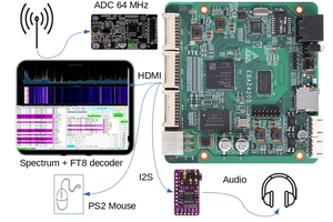
 Guido
Guido
 Jonas Norling