kamalkedin123
Principle:
The rise and fall of the current across the LED is regulated by the proper terminology of 555 Timer IC. By default the first output of the circuit LED is at the rest or OFF. Whenever the clock is applied and trigger is simulated externally the shifting and transition of LED blink and flash takes place, this swapping of output is termed as the chaser circuit. Let’s make our project and understand its functioning practically.
Attention Here:
As we all know our world is suffering from highly infected pandemic disease COVID-19. So, for the awareness and social responsibility we are providing 0 profit selling disposable medical things.
Please check out and wear masks when going out!
Get all the things from here
- Infrared Thermometer
- KN95 Masks (10 pcs)
- Disposable Surgical Masks (50 pcs)
- Protective Goggles (3 pcs)
- Disposable protective coveralls (1 pc)
- Disposable Latex Gloves (100 pcs)
Components Required:
- 555 Timer IC (1)
- LED lights (10)
- CD 4017 IC (1)
- 470, 1k, 47k Ohm Resistors (1)
- 1uF Capacitor (1)
- Bread Board
- (5-15)V Power Supply (1)
- Connecting Wires (as required)
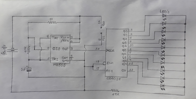
Circuit Diagram:
Procedure:
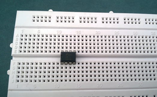
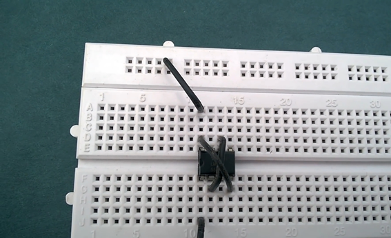
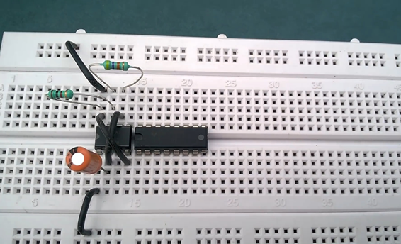
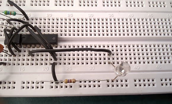
1. Place the 555 Timer IC on the bread board with its notch facing up, as shown in the figure below.
2. Now connect Pin 1 of 555 Timer IC to the negative rail and Pin 8 to the positive rail of the bread board
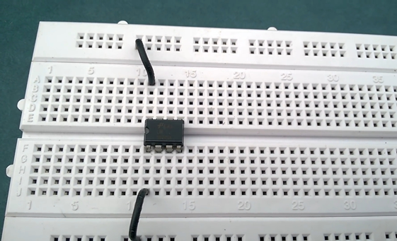
3. Now place the bread board connectors between pin 2 and 6 of the IC and another one to the Pin 4 and 8 and shown below
4. Now place 1uF Capacitor with its negative terminal connected to the pin of the IC and positive terminal to the Pin 2 of the IC
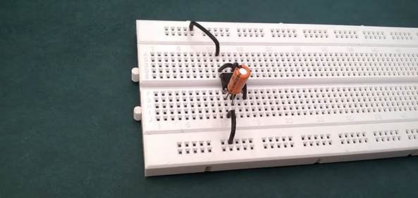
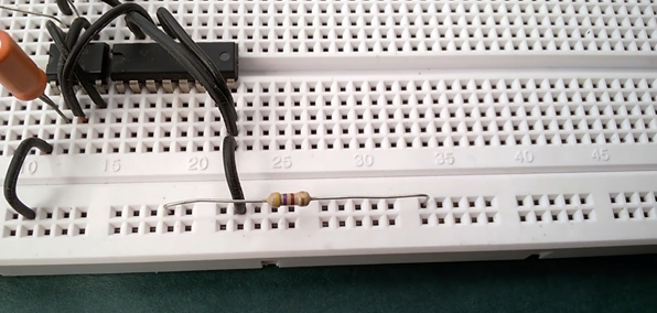
5. Place 1k Ohm resistor on the bread board with its terminal connected to the Pin 7 and 8 of the IC
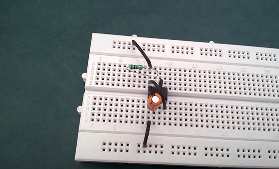
6. Now place 47K Ohm Resistor between pin 6 and 7 of the 555 Timer IC
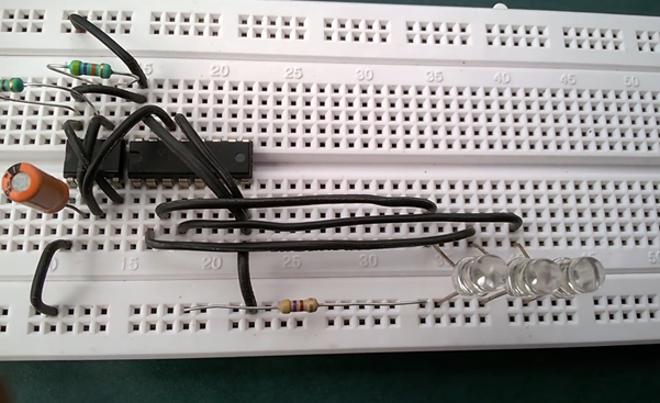
7. Place 4017 IC on the bread board with its notch facing parallel to the 555 Timer IC as shown in the figure below
8. Connect pin 16 of the 4017 IC to the positive rail of the bread board and pin 8 to the negative rail
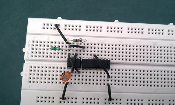
9. Connect bread board connectors between pin 8 and 13 of 4017 IC and another between pin 8 and 15.
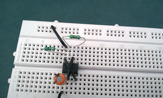
10.Place 460 Ohm resistor on the bread board with one of its end connected to the positive rail and other end to parallel.
11.Now connect pin 3 of the 4017 IC to the first LED as shown in the figure according to the circuit diagram
12. Similarly Pin 2 to the 2nd LED, pin 4 to the 3rd LED, pin 7 to the 4th LED as per the circuit diagram
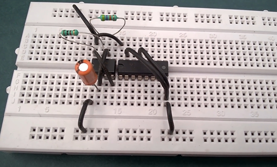
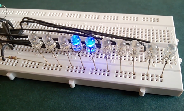
13. Further connect 5th, 6th, 7th, 8th, 9th and 10th
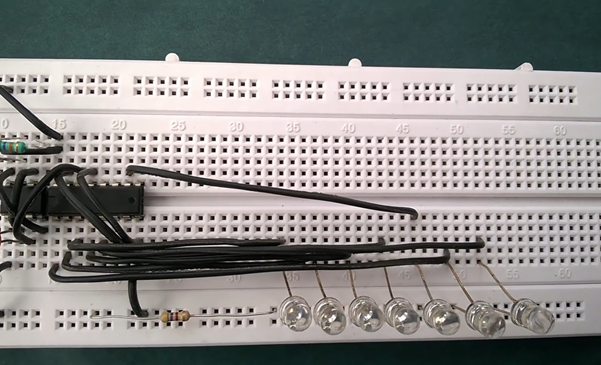
also as per the circuit diagram. Our circuit will look like this
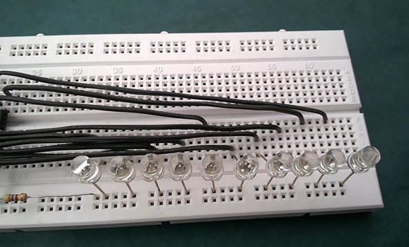
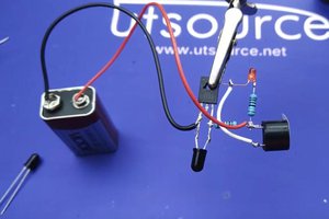
14. Now connect the power supply as shown in the figure below to the respected rails of the bread board.
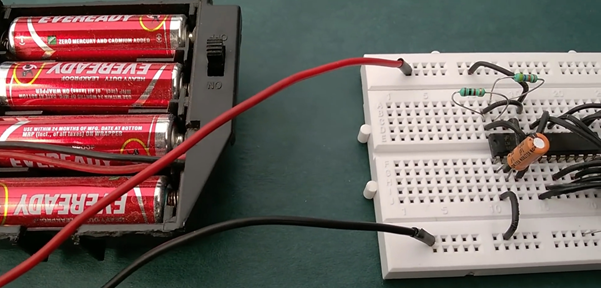
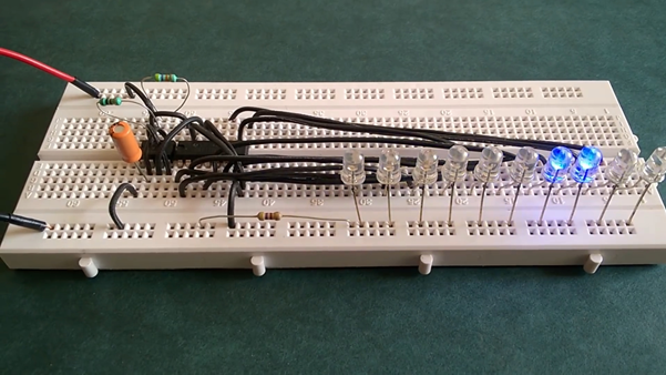
15. Now our LED chaser circuit is ready
16. The state of the LED will shift from one to other with the applied trigger at the input side of the IC
So this is the basic principle and working operation of LED chaser electronic circuit. So what are you waiting for do it and grab the practical knowledge.
Thank You.

 Electroniclovers123