 benw
benwRX-Modulus:
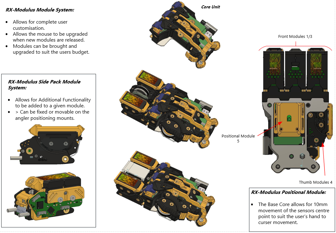
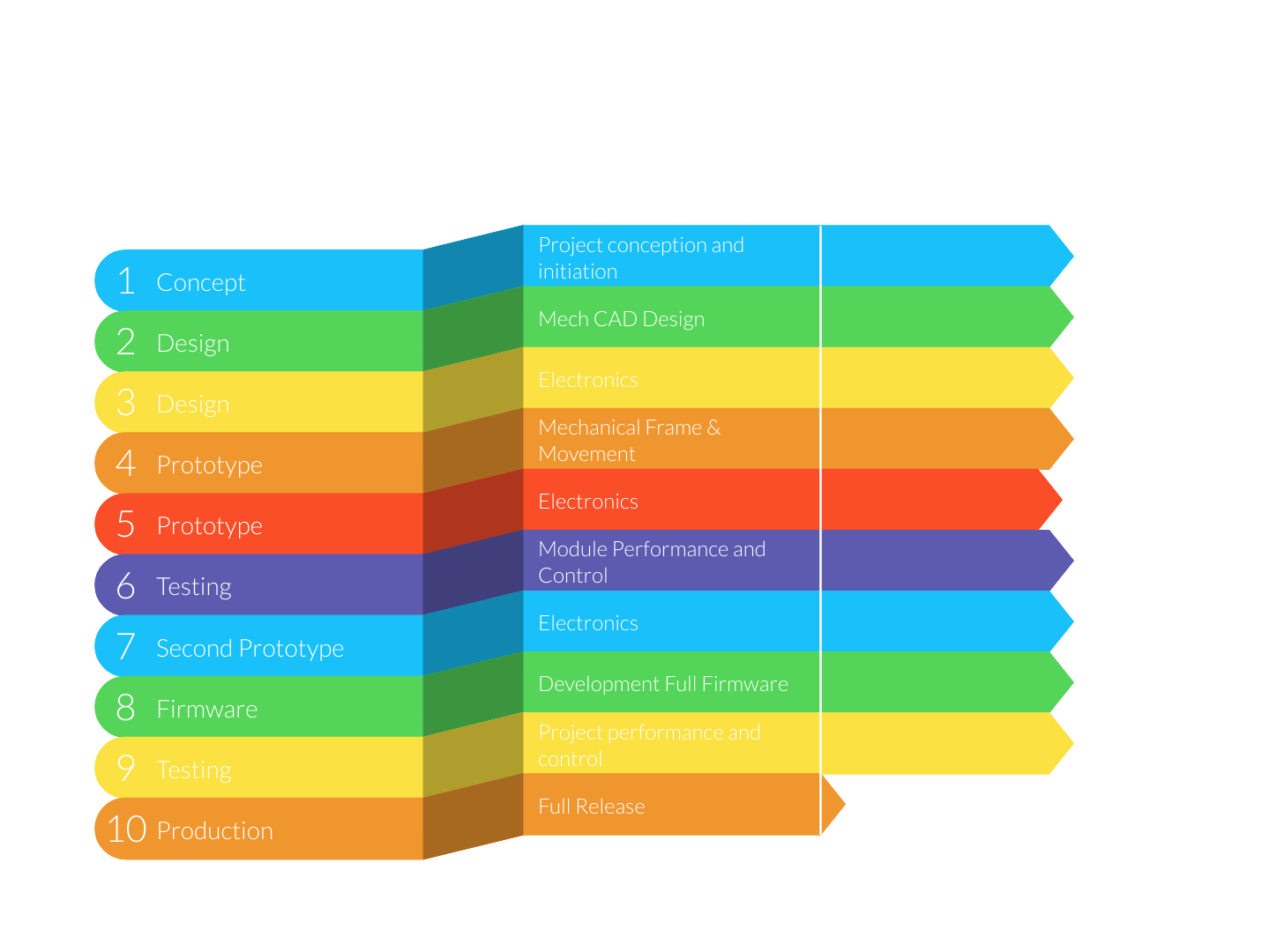
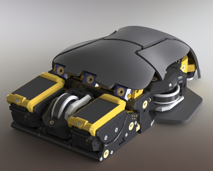
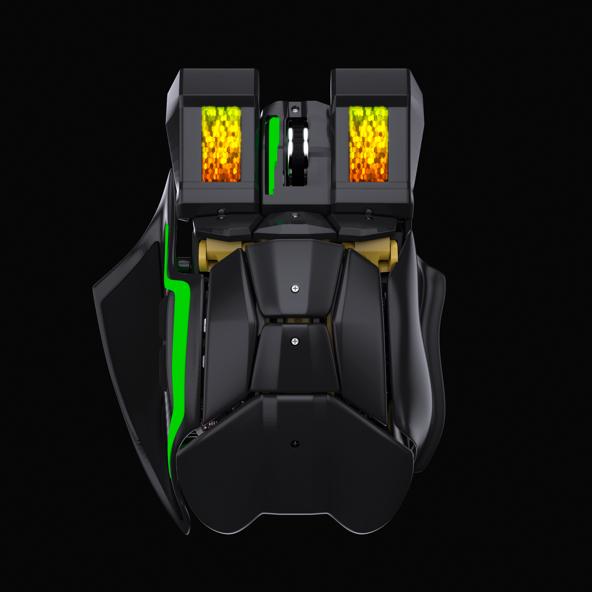
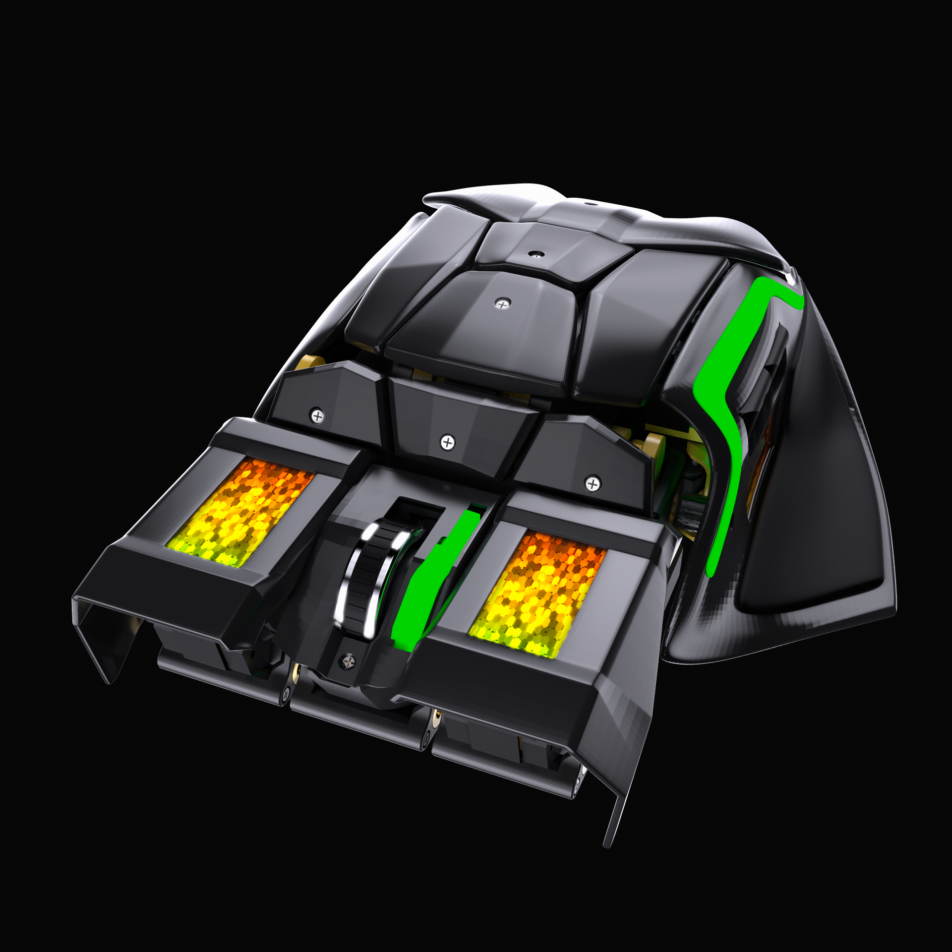
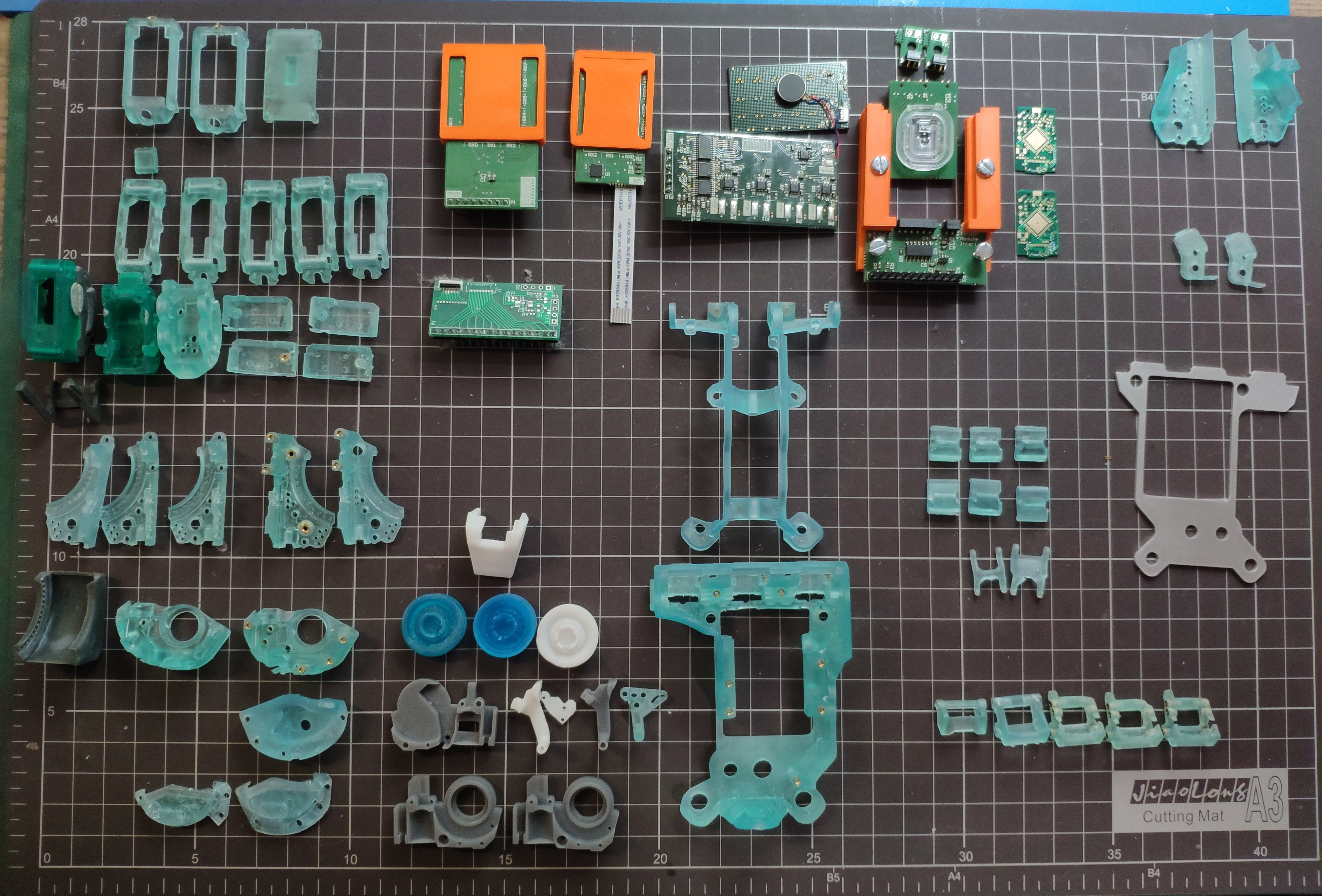
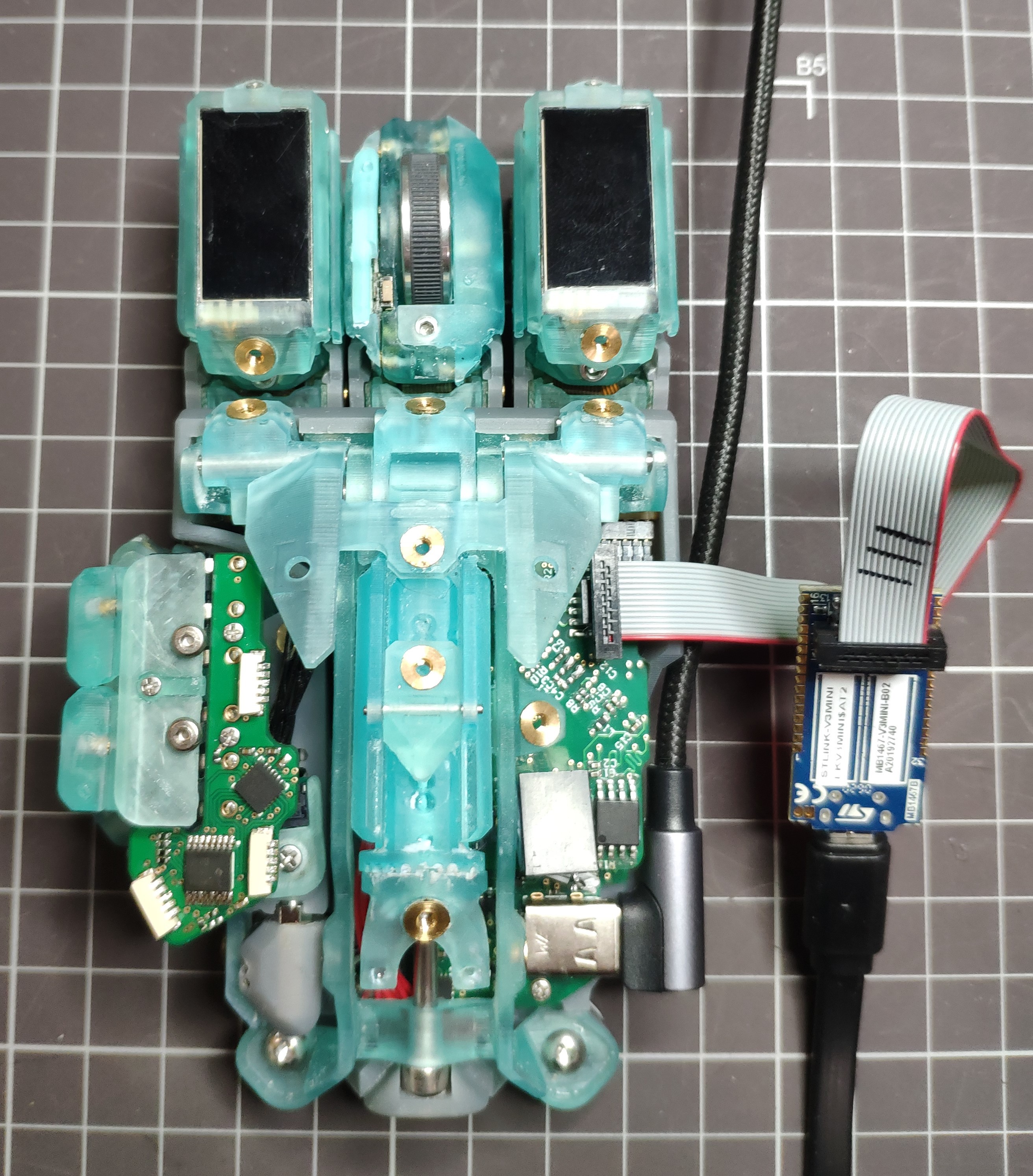
RX-Modulus is an opensource fully modular computer mouse that strives to innovate and empower users and the community to have better than what currently available to purchase. No more do you 'have to get used to' a mouse. RX-modulus allows the user to fully customise their mouse to suit them. The module system allows for different mouse configurations and end user experiences. All modules can be upgraded when required or changed to suit the users budget.
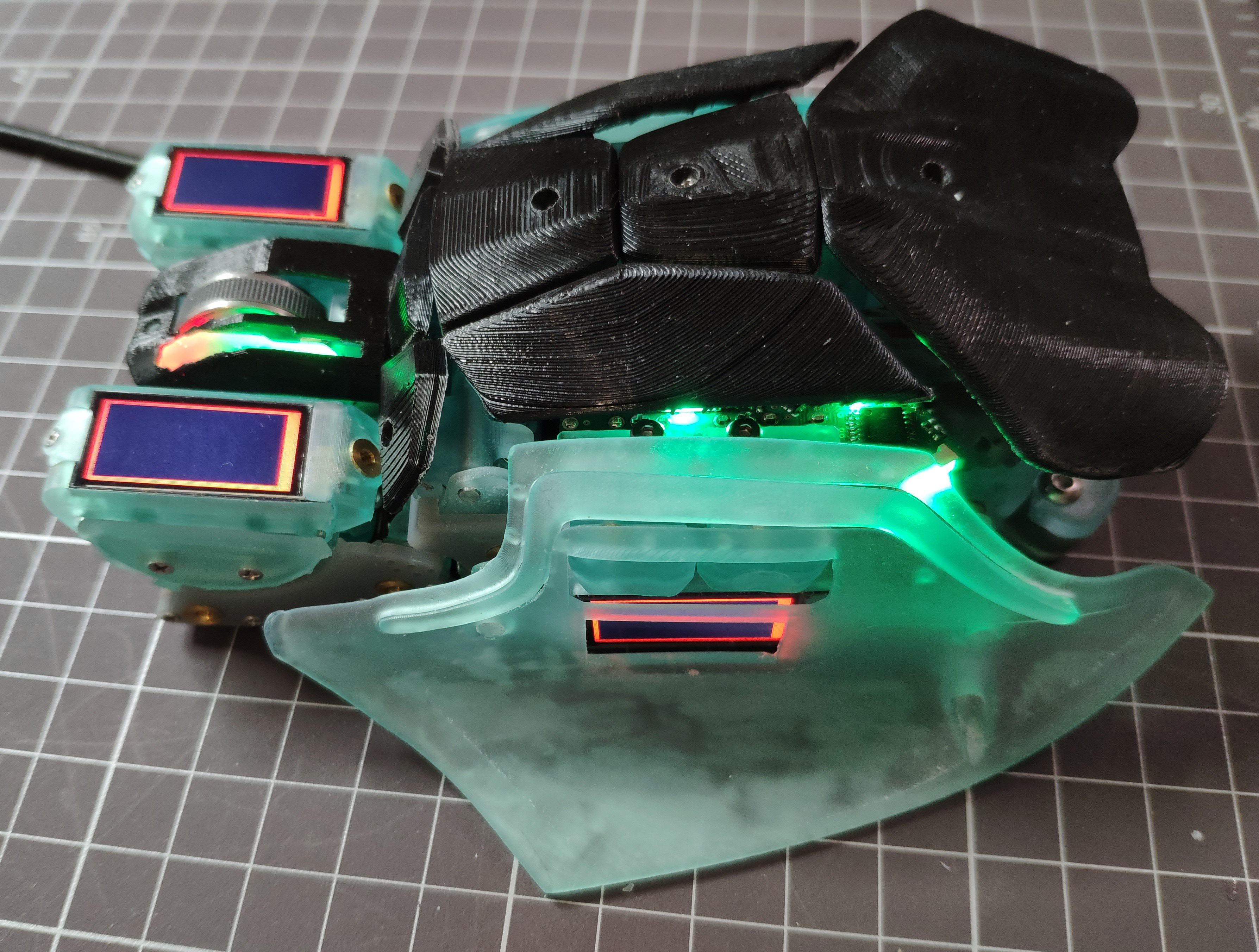
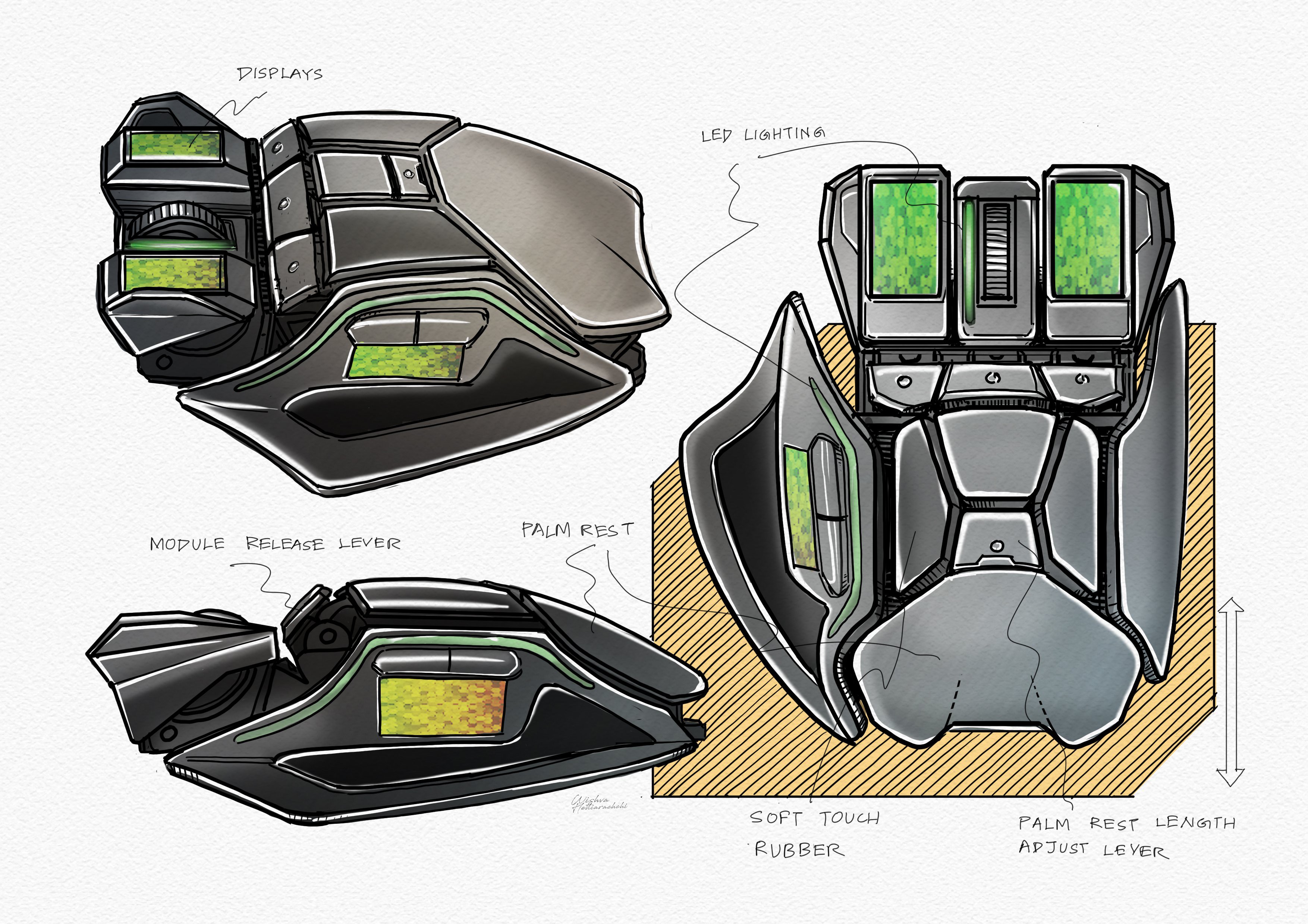
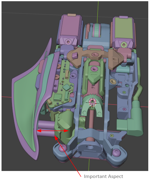
Adjustable Shape:
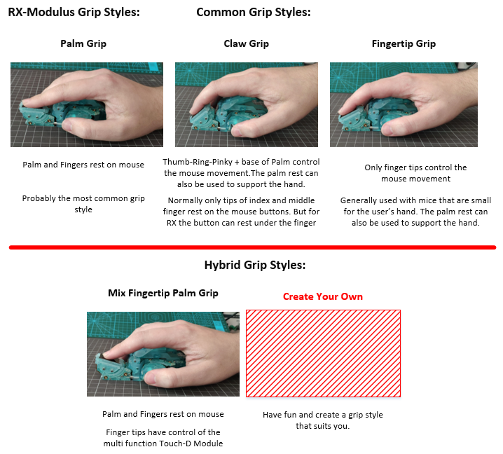
The RX-modulus allows the mouse to be positioned to suit the users hand in their ideal comfortable position. This system has been built into all modules which enables multiple mouse grip styles to be employed. The panel system is used to define the mouses final shape. The mouse is also compatible with different hand sizes, see the project log: https://hackaday.io/project/171196-rx-modulus-completely-modular-mouse/log/179826-by-popular-demand-size-matters for full details.
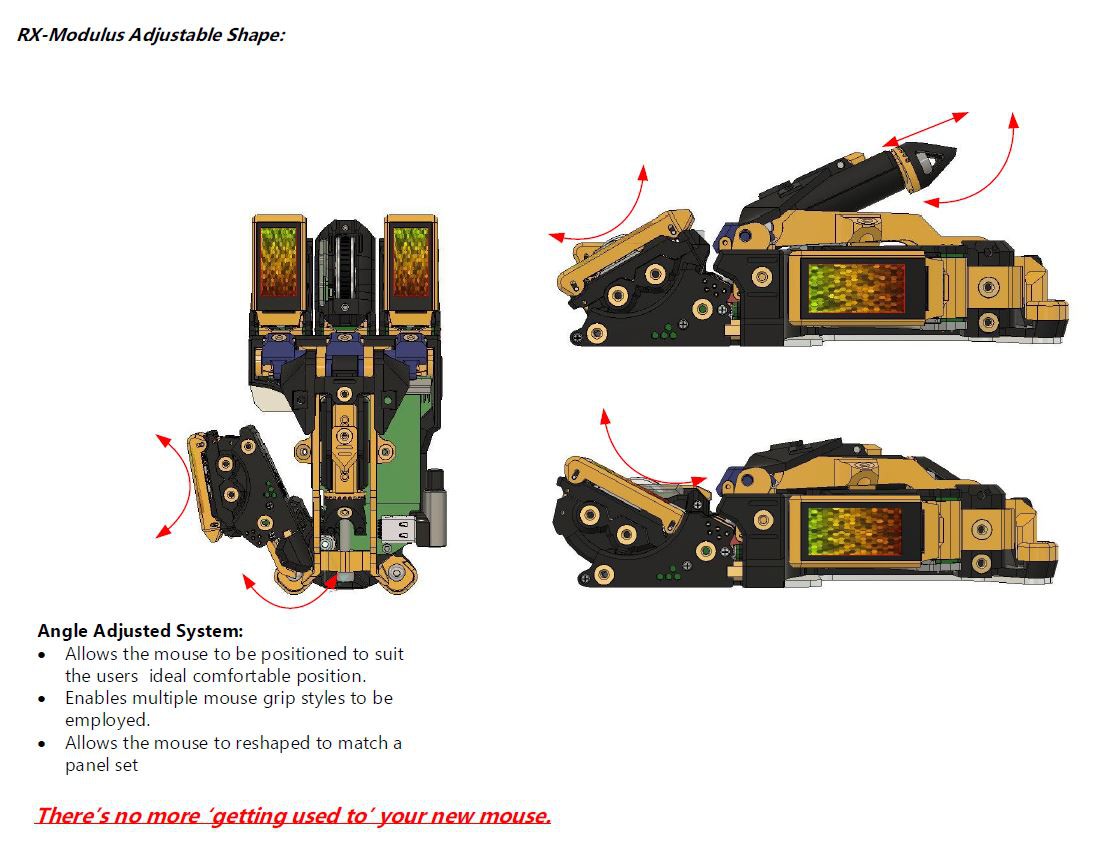
The RX-modulus also allows for mouse grips to be used.
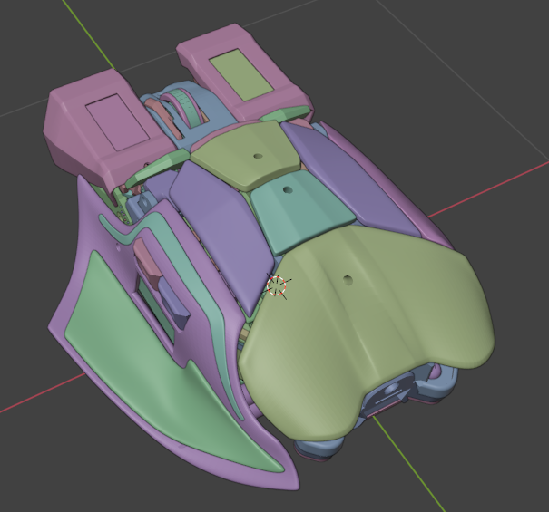
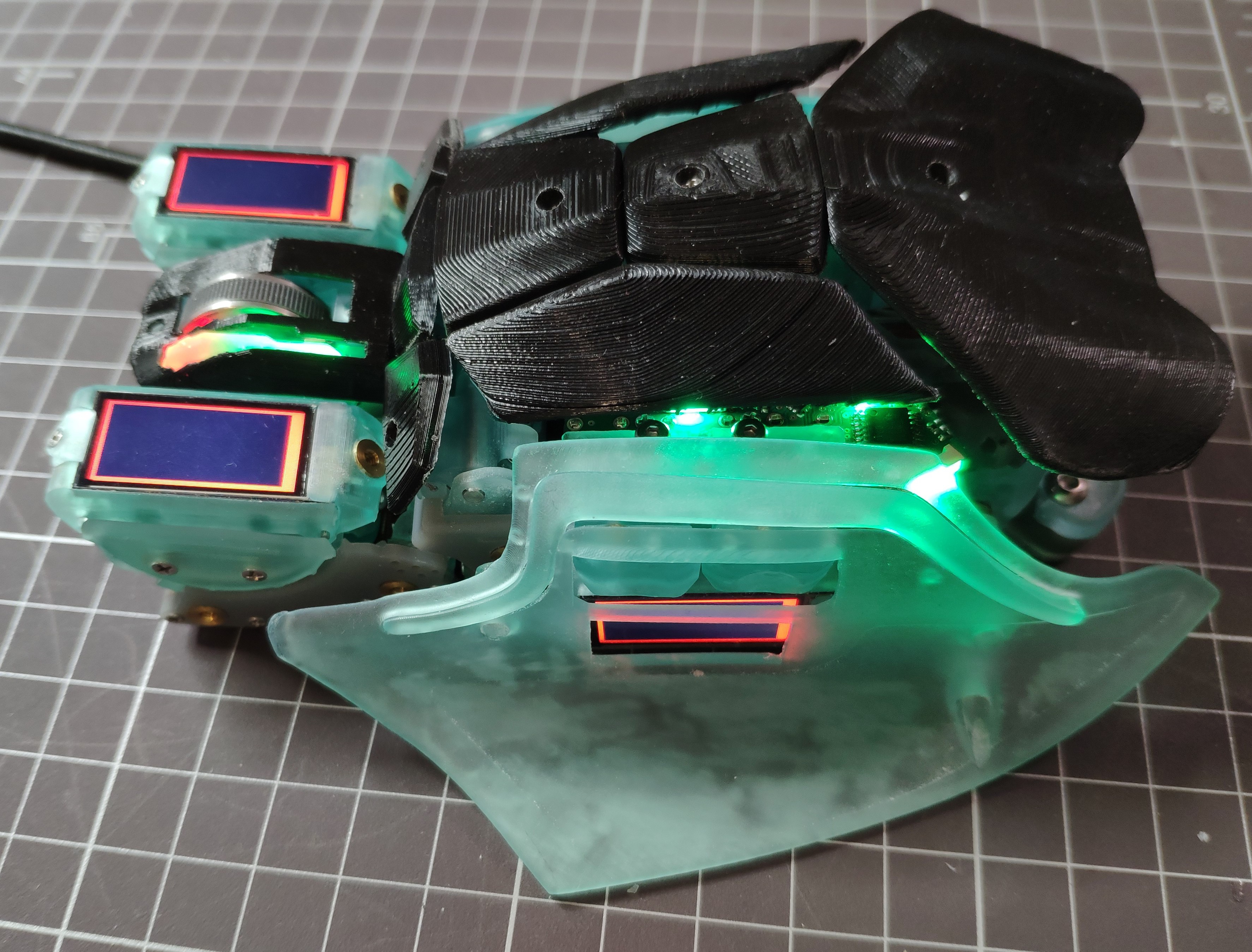
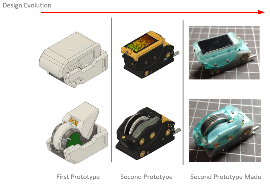
The Panel System: (Developing)
The Panel System is used to define the final shape of the mouse. This system has been developed into all modules and cores. There will be three starter panel sets to choose from (which still need to be designed), additional sets can be printed but my goal is to empower the community to design and share their mouse panel sets which in turn enriches the mouse experience. See the project log https://hackaday.io/project/171196-rx-modulus-completely-modular-mouse/log/178935-alot-of-progress for the first draft of the panel system take shape. The the first prototype shell please see the following log: https://hackaday.io/project/171196-rx-modulus-completely-modular-mouse/log/184526-designing-the-first-shell
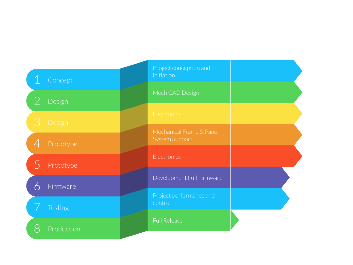
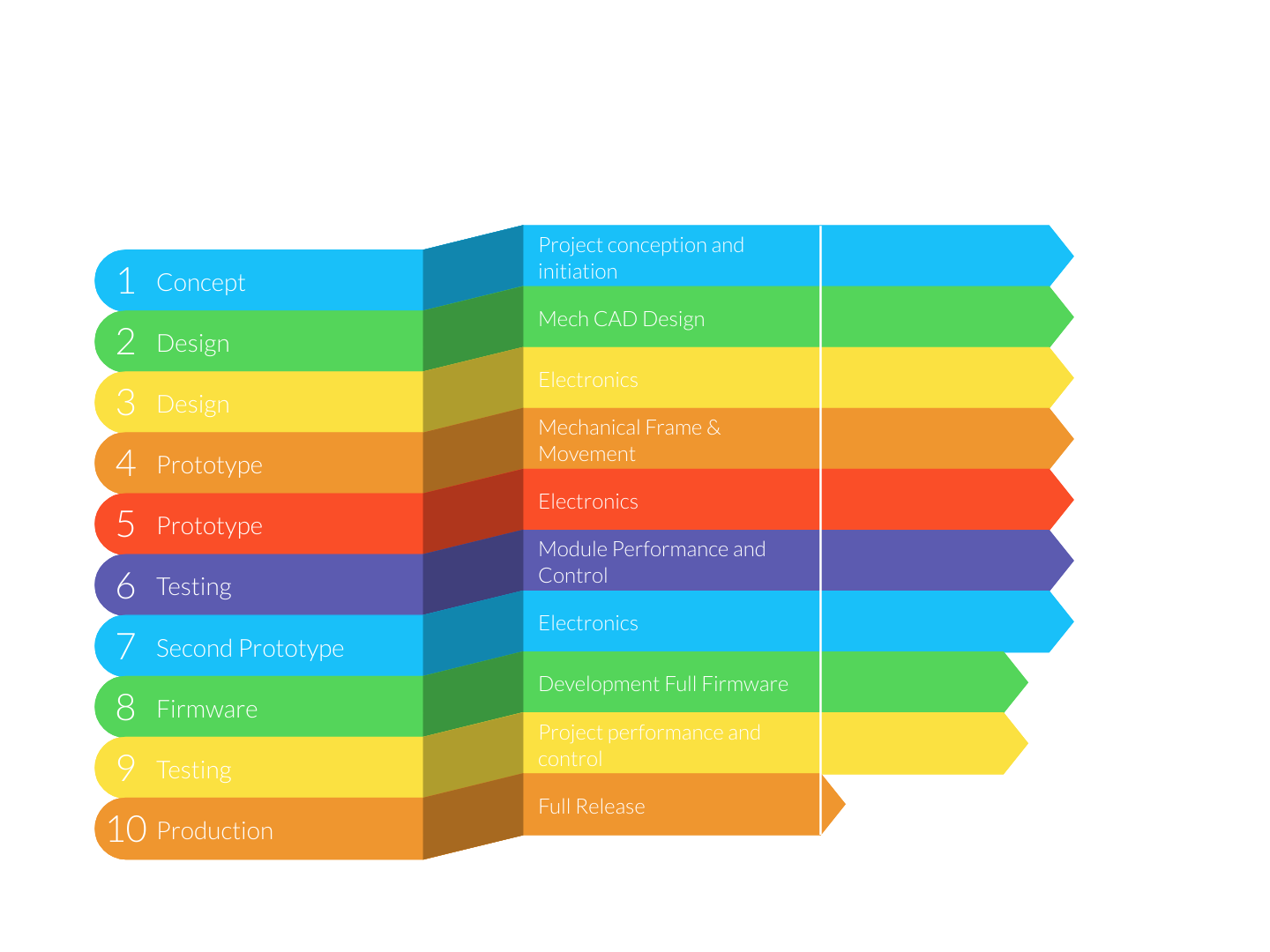
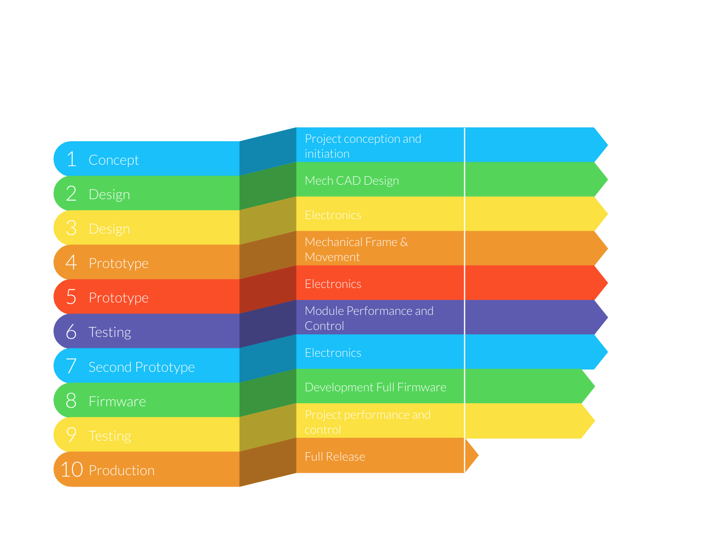
Current Modules:
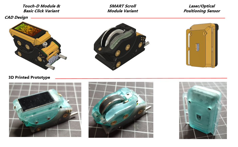
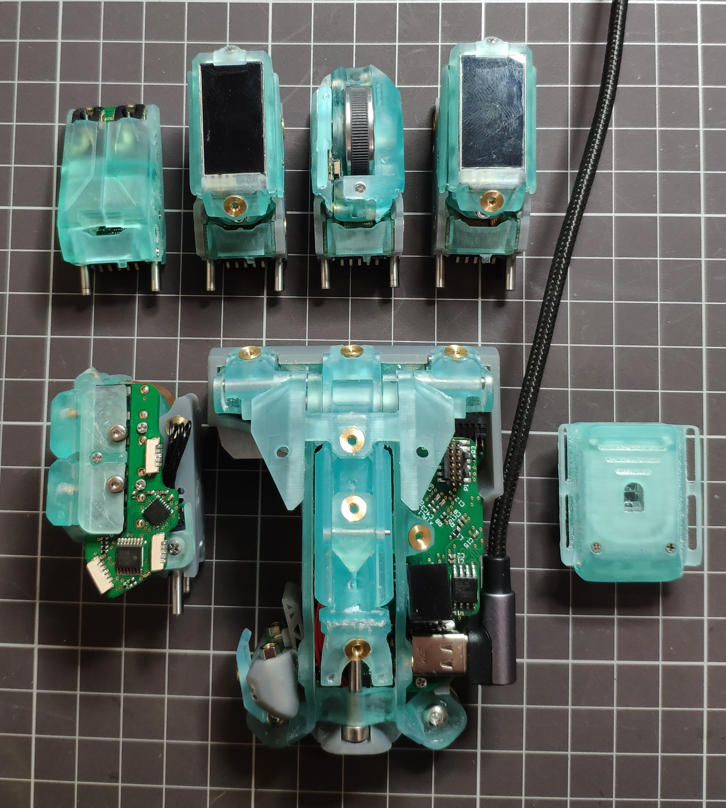
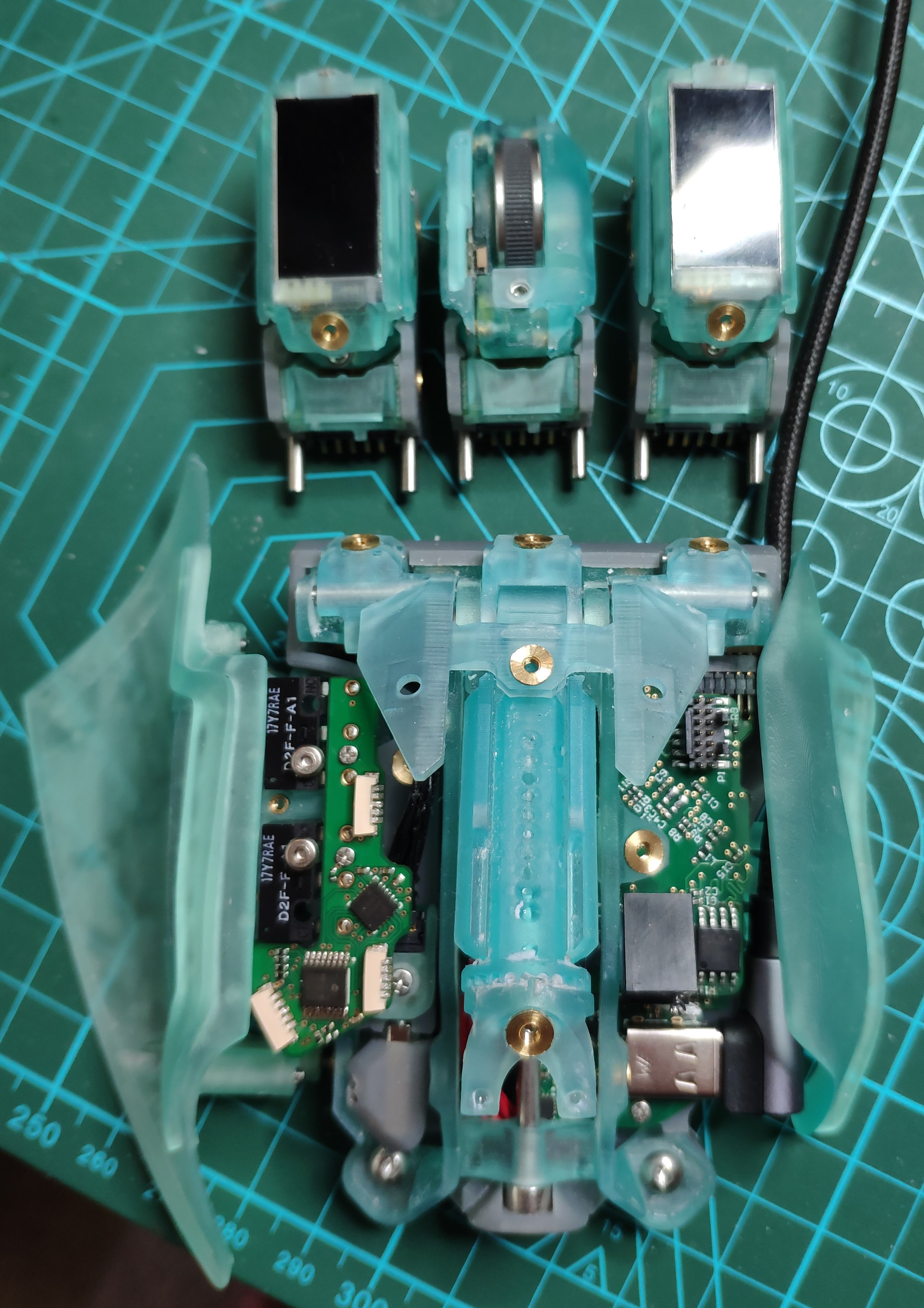
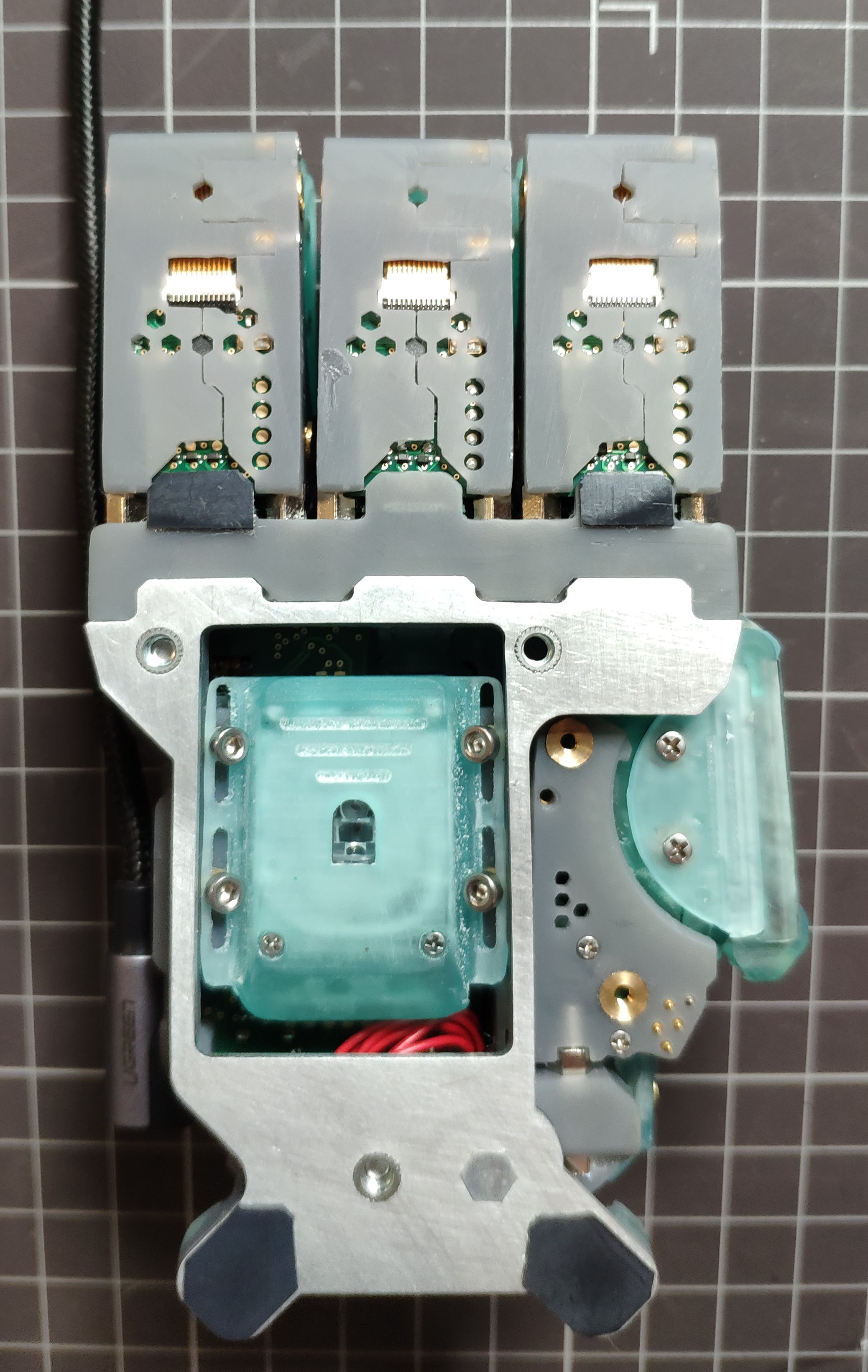
There are currently three modules in development which are:
- Touch-D & Basic Click Variant
- Touch-D variant enables custom TFT display interfacing and capacitive positioning to enrich and enhance interfacing capabilities.
- Basic Click variant would be the normal click interface all mouse interfaces have.
- SMART Scroll Module
- Adjustable scroll feedback.
- Replaceable adjustable feedback plate.
- Contact less positioning for absolute positioning and operational longevity.
- Laser/Optical Positioning Sensor
- Allows the user to swap and change the sensor whenever required.
All Modules support the 'Side Pack Module System' which allows for additional functionality to be added, like for example internet page back and forward. Please see the project log: https://hackaday.io/project/171196-rx-modulus-completely-modular-mouse/log/177754-still-waiting-but-the-work-continues for a sneak peak at the Side Module Connection Pack and Side Module Click Pack.
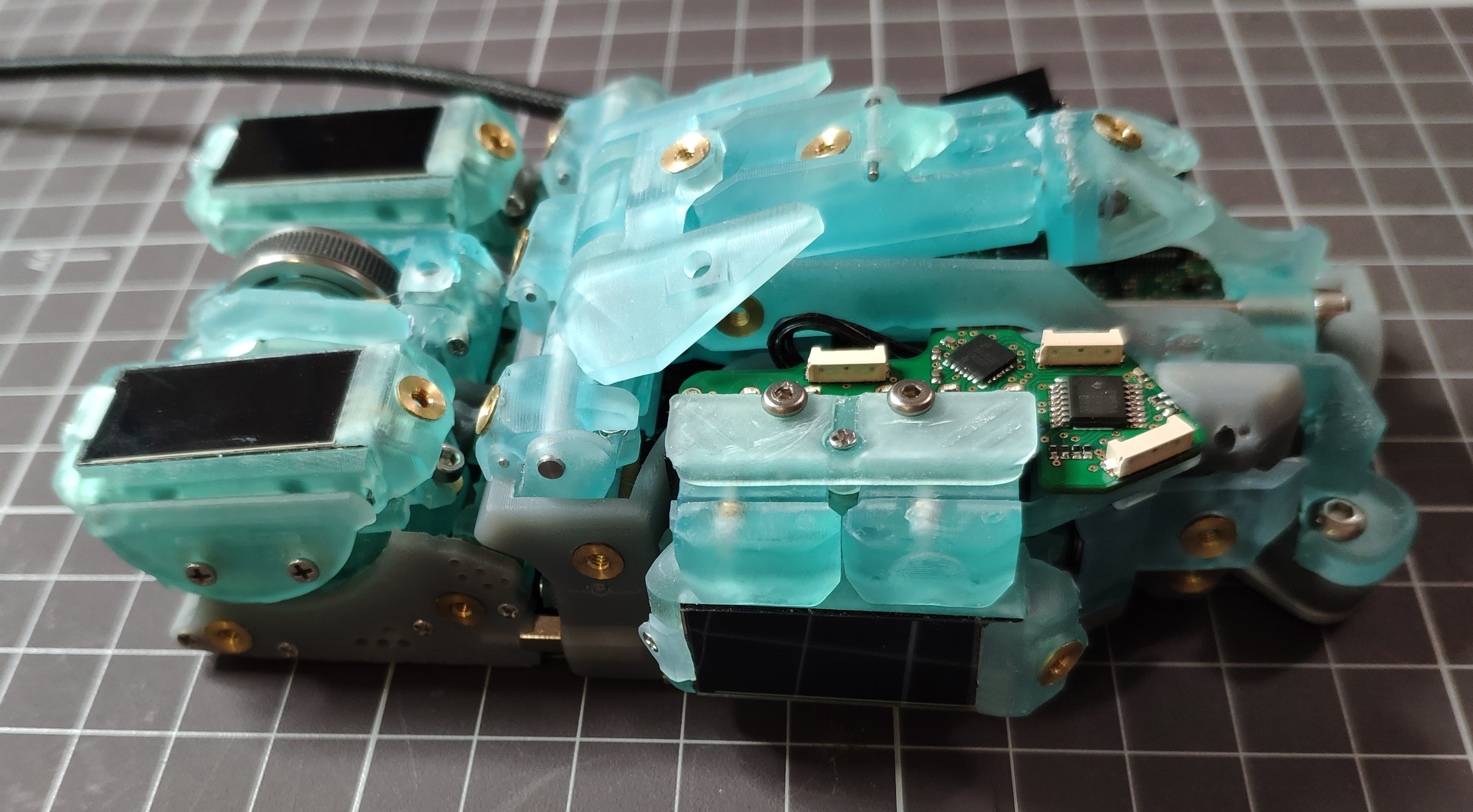
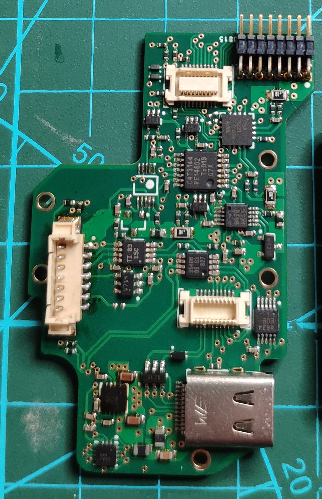
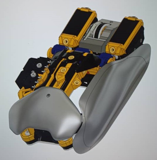
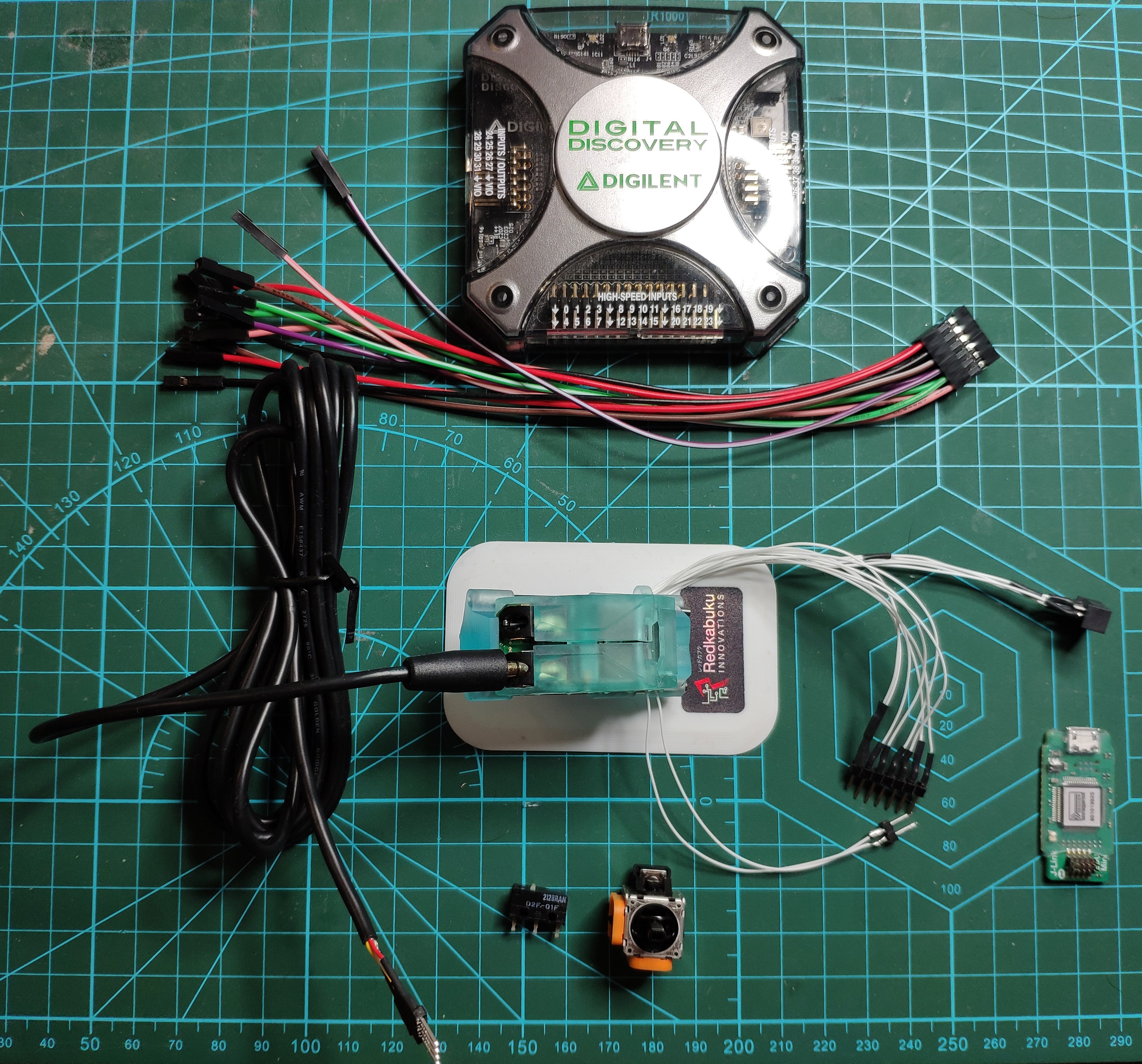
Hardware & Right to Repair:
All the hardware used on the RX-modulus is 100% built from scratch. This is to ensure a high level of reliability and as we are sworn enemies of planned obsolescence and have designed the hardware to last as long as possible which is good for your pocket and the environment. With us having complete control over the build of the hardware we can ensure that this mouse is the first mouse designed to be repair friendly. All hardware schematics will be released after a complete system and module performance test has been completed.
Software:
The software will of course be open-source. There will be a official full release for every element of this project after a complete system and module performance test has been completed. This to ensure that 'you' the user are using tried and tested software.
How does our idea benefit those with cerebral palsy or other physical disabilities?
The target audience for the modular mouse is ‘everyone’. However, the flexibility and modularity that benefits everyday users and even hard core gamers could also be highly beneficial to those with minor disabilities. People with physical disabilities...
Read more »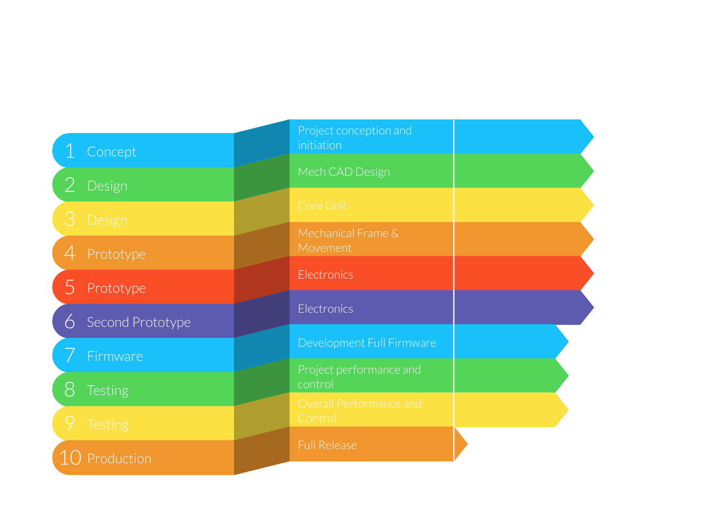


 Michael O'Toole
 E. N. Hering
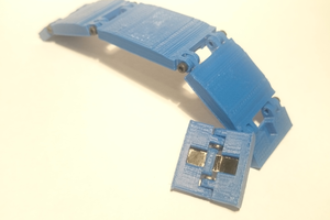
 novirium
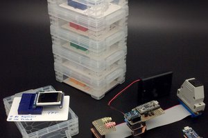
 William
I hope you complete the project. Wish you luck.