 Adam Demuri
-
1Prepare
You'll need these tools:
- Soldering iron
- Side cutters, to trim the leads
It'll be easier if you also have these tools:
- Multimeter
- Hot glue gun
- Resistor lead bending tool (optional, but nice)
- Alligator clip wire (for testing the board before attaching the battery pack)
-
2Order PCB
Download the gerbers zip file, and upload it to a PCB manufacturer. I use JLCPCB, which is fast and cheap. The default PCB options should be fine - feel free to change the color, if you like.
At time of writing, price to get 5 PCBs, including shipping to the US, was $19, with order-to-door time of about a week. You can use PCBShopper to look for a cheaper option, or share the boards among friends to bring down the unit cost!
-
3Order components
The BOM csv file lists the components you'll need. You can upload this file to Digikey using their BOM support to automagically add the components to your cart. At time of writing the total cost of the components was about $15. If the battery holder is out of stock, you can substitute the similar part with a ribbon.
You'll also need to buy an antenna with a BNC connector. I used this one. Feel free to try different antennas - this isn't a precise device!
-
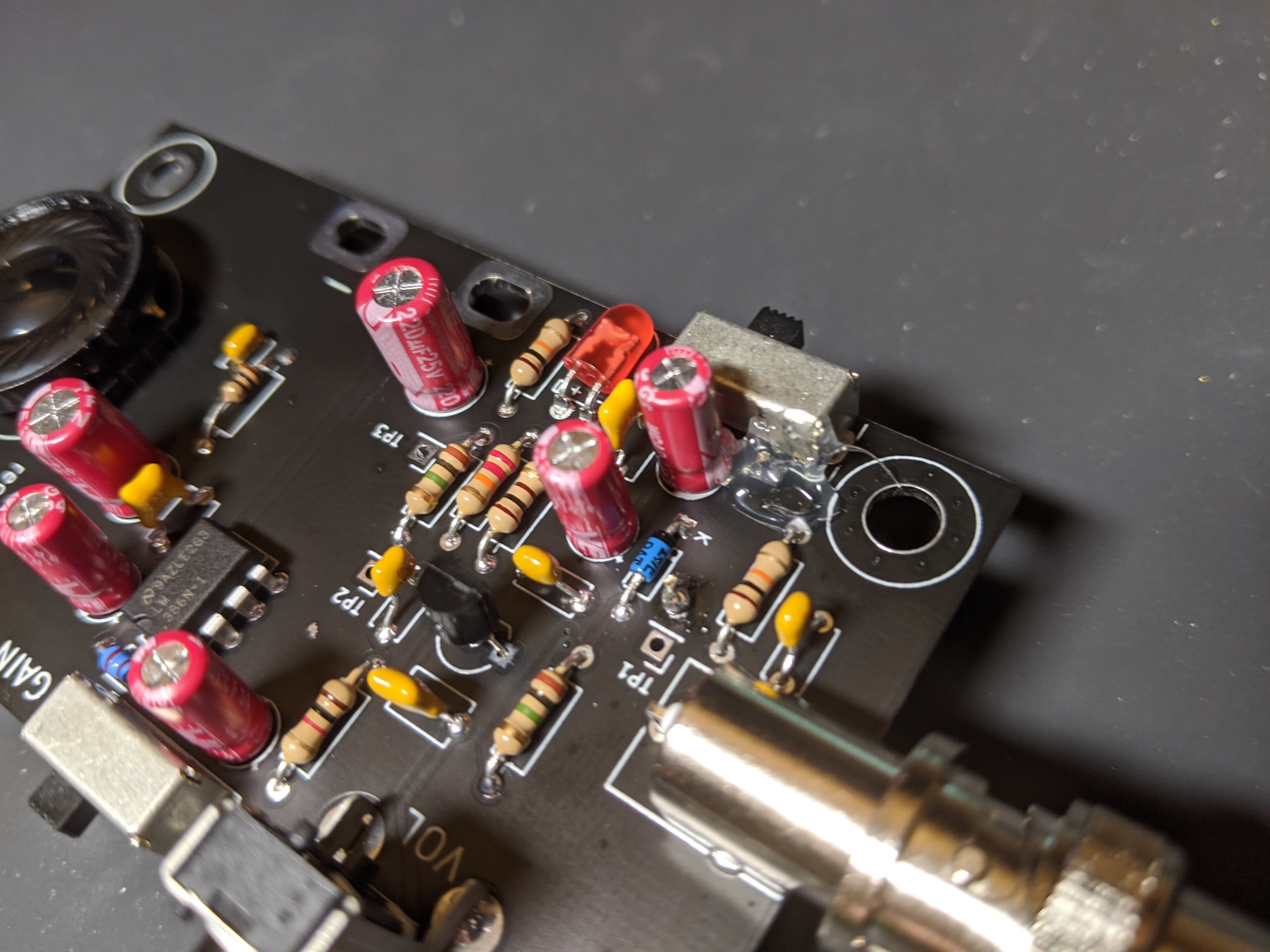
4Assemble board
Solder the components onto the board. The GitHub repo contains an interactive HTML bom, which shows you where to place the parts. You'll need to download that HTML file and open it in your browser. The components aren't too tightly spaced, so you can solder them in pretty much any order. I'd recommend doing the electromechanical components (e.g. switches) last. Also, don't solder on the battery holder yet.
Most of the components are pretty straightforward. The BNC connector for the antenna is tricky. The two large lugs are connected to the entire case, which sucks the heat out of the solder joint. Even with my temp-controlled iron, it took me almost a minute before the solder wetted to the lugs. Be patient, and make sure that it's well-soldered, since the antenna will put some physical strain on the component. And remember that the BNC connector will be quite hot after soldering - give it some time to cool down!
-
5Test board
At this point, you should have everything soldered on the board except for the battery holder. Since the battery holder will block the bottom of the board, we're going to test the board.
Attach the antenna to the connector. If you have alligator clip wires, attach the '+' and '-' slots on the side of the board to the battery holder (put some batteries in it first). Make sure you don't reverse the polarity! When you do this, the LED should come on, and if you turn up the volume, you should hear some faint noise (or possibly loud noise, if you're near something radio-y). Try bringing the receiver near something that plugs into the wall - you should hear a low buzzing sound (from the 50/60Hz), plus other sounds depending on the device. If you do, then congratulations - you can move onto the next step. If not, continue to troubleshooting.
If you don't have alligator clip wires, you can insert the battery pack into the holes and hold it so that the PC pins make contact with the holes. Be careful that you don't short the lead of the battery pack to the metal body of the switch.
Troubleshooting:
If your device isn't making any sound yet, then you need to troubleshoot what's wrong. First, examine the solder joints, and look for any 'cold' solder joints, or bridges between adjacent pins. All solder joints should be shiny and concave-ish.
If that doesn't reveal any issues, check the test points (labeled TP1, TP2, TP3 on the board). Here are the expected voltages for the test points, with fresh batteries and the antenna not connected:
TP1: 0.24v
TP2: 0.53v
TP3: 1.65v
If your voltages are close to these, then look for an issue in the audio section. If they do not match, double-check the RF section. Check the HTML bom and the schematic to help you troubleshoot.
-
6Attach battery pack
I use hot glue to secure the battery pack to the PCB. Make sure the circuit works before doing this - the battery holder blocks access to most of the components' holes.
Before glueing, dry fit the battery pack, and make sure that it sits relatively flat and close to the PCB, Trim any leads that stick up too far, making sure not to cut off too much and damage the solder joint.
Squirt some glue onto the board where the battery pack sits. Quickly insert the battery pack into its holes, and hold it until the glue sets. I also added a little glue on either edge of the battery pack after this. I melted the plastic of the pack slightly when doing this, which is probably good since it means the glue will adhere well, but don't use too much!
The positive battery pin is pretty close to the metal power switch body, so I also added some hot glue between the two to prevent shorts.
![]()
-
7Use it!
You've completed the device! Try holding it with the antenna near anything that uses electricity. The gain switch will toggle between low and high gain settings. The power consumption seems to range in 10-30mA, depending on signal strength,
All-Band Receiver
Device that makes the normally-invisibile world of RF audible.
Discussions
Become a Hackaday.io Member
Create an account to leave a comment. Already have an account? Log In.