Giorgio Rutigliano
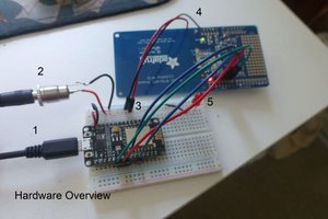
I used as CPU a DOIT Esp32 DevKit v1. Just two other components are needed: a SD card as mass memory device (size is not important - in that times PCs memory was limited to a few handfuls of kBytes - but it must be compatible with the 3.3V power supply) and a card socket - I used one taken from the galaxy of Arduino add-ons. It is easy to get all components for less than 10 bucks.
SD card wiring is easy, just 6 connections. The scheme for my board is D5 -> CS, D18 -> SCK, D19 -> MISO, D23 -> MOSI, in addition to +3.3V and GND. Take in account that different boards could have different pin mapping, so check the specs to identify the correct pins. For cabling I've found that is better not to use a breadbord, since ESP pins are a bit bigger than usual and could deform breadboard's contacts. I've used jumpers for testing, then I moved the project on sockets soldered on a stripboard for the final version.
The software I used is the excellent RunCPM emulator written by Marcelo Dantas and available on GitHub. It can be build and downloaded on ESP32 using Arduino IDE. RunCPM requires the SDFat library: there are two ones available for Arduino IDE, and the correct one is Ardafruit fork. The library needs also a simple configuration hack, changing two declarations in SdFatConfig.h file:
#define ENABLE_EXTENDED_TRANSFER_CLASS 1 (around line 71)
#define ENABLE_SOFTWARE_SPI_CLASS 1 (around line 87)
Source also needs to be configured, setting the right boad definition include file on RunCPM.ino:
#include "hardware / esp32.h" (around line 23)
and the lines used to connect the SDCard on hardware/esp32.h
SdFatSoftSpiEX <19, 23, 18> SD; // MISO, MOSI, SCK
#define SDINIT 5 // CS
#define LED 2 // DOIT_Esp32 = 2
#define LEDinv 0
#define BOARD "DOIT_Esp32"
At this point should be possible to compile and download the software on the board.
The SDCard holds just CP/m related files. It must be formatted with a single FAT partition. CCP file must be placed at root level. Then it is necessary to create two nested directories: A at root, and 0 (number zero) inside of A, then place the content of A.ZIP file inside of the latter one.
Directories at root level named from 'A' to 'Z' as seen by the emulator as virtual disk drives, directories named from '0' to '15' inside of them are 'user areas'.
Communication is done using a terminal emulator, you can use putty on windows and minicom on linux. Both have ANSI/VT100 emulation. Communication parameters are 9600/n/8/1.
A more detailed dscription is available on my blog:
microCP/M: hardware
microCP/M: software
(in Italian)
Happy retrocomputing!
 Just4Fun
 Andrey Skvortsov
 doctek