 Neil Mundt
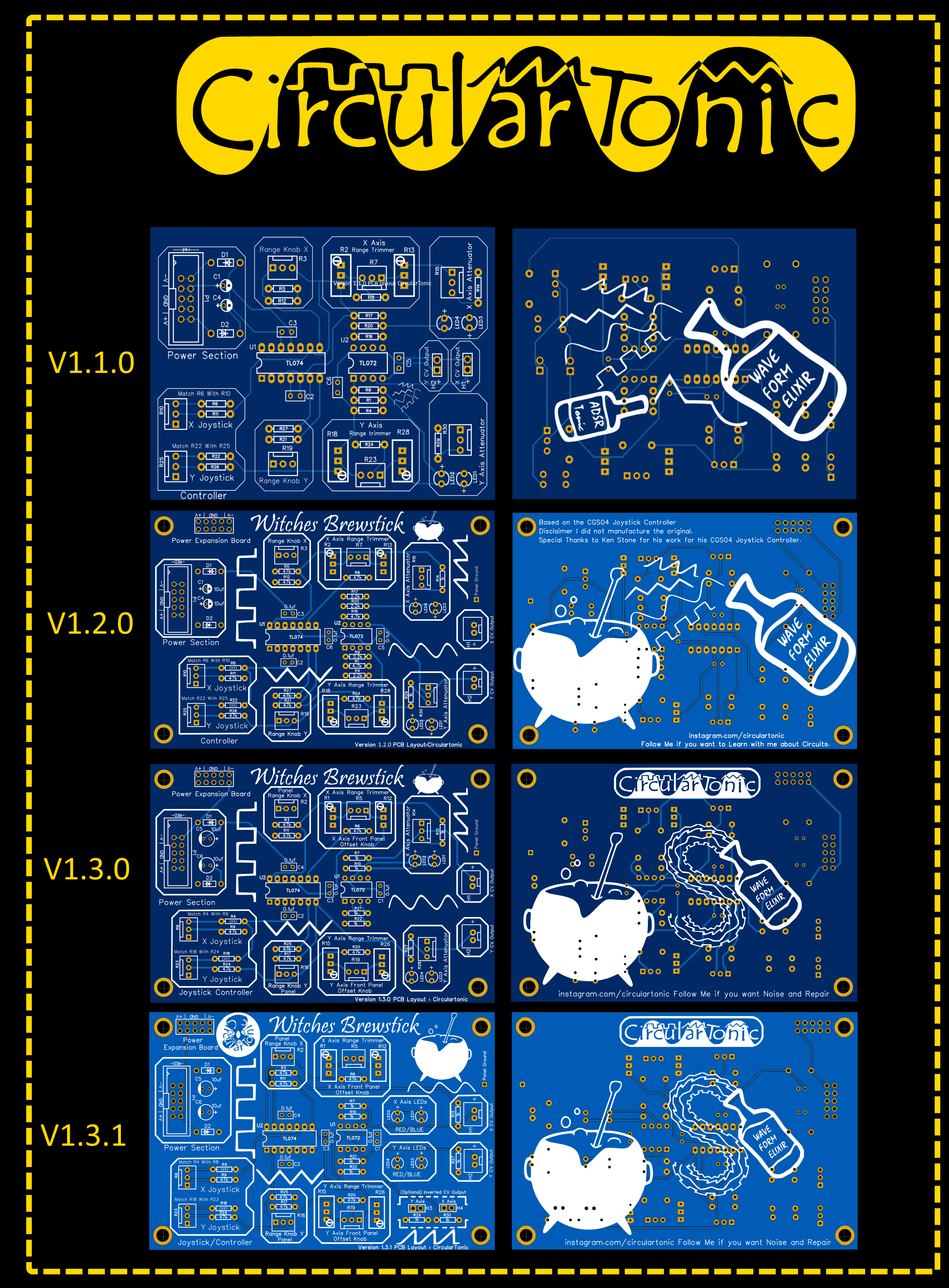
V1.2.0
It worked as intended surprisingly:)
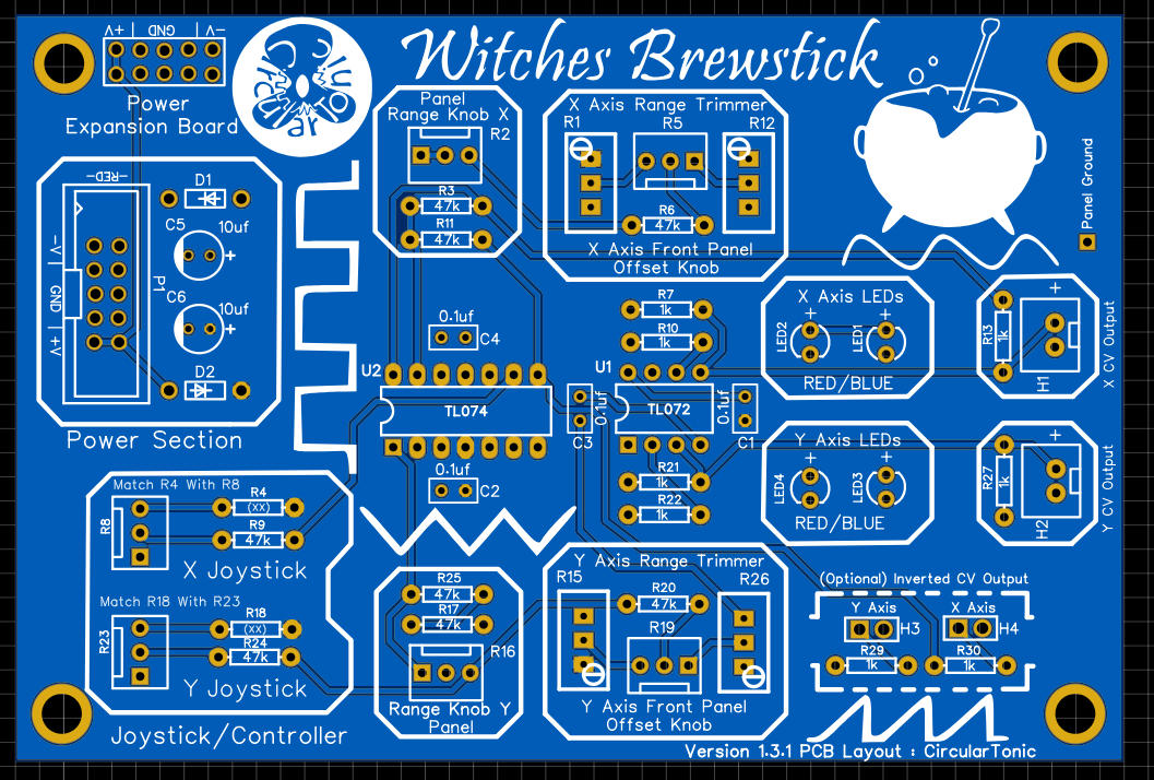
V1.3.1
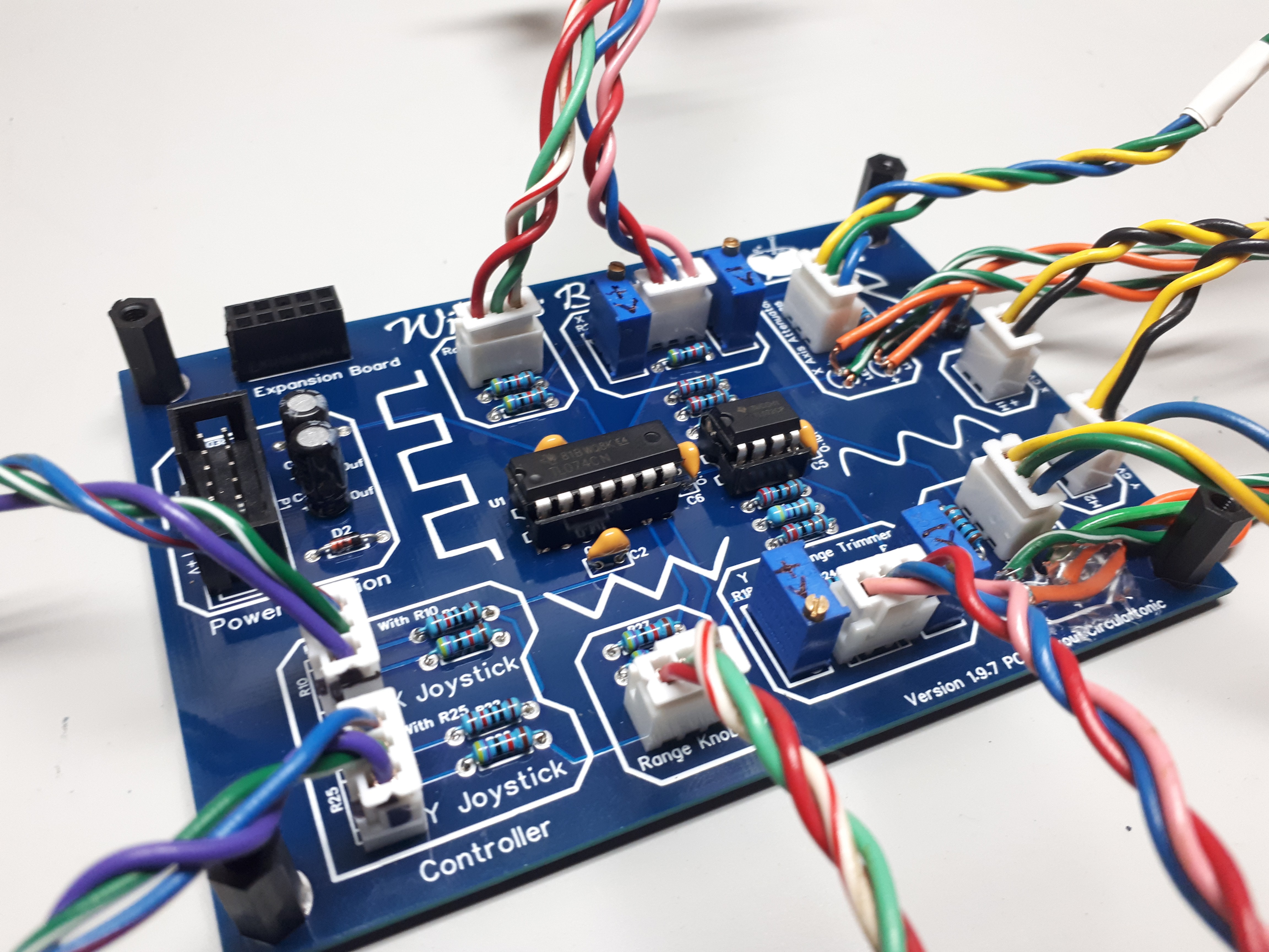
Features
•X and Y CV for Joystick or other resistive pots
•Offset/Range Panel Knobs X/Y
•Offset Postive/Negative Voltage output LED Indication
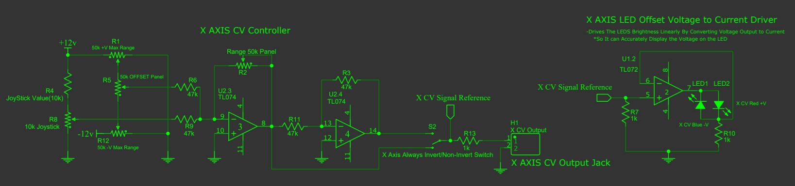
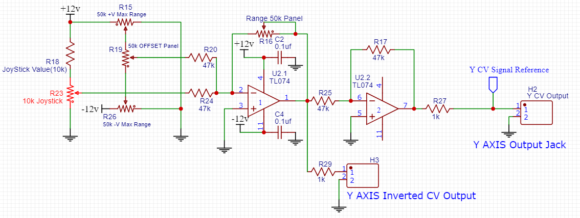
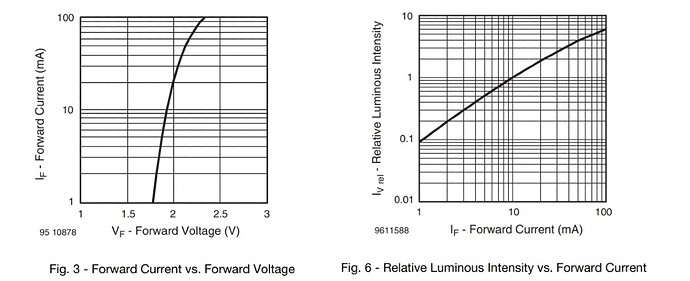
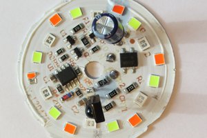
The Redone schematic for witches brew module. LEDs are now driven linearly. The LEDS Brightness Linearly controlled By Converting Voltage Output to Current method *So It can Accurately Display the Voltage on the LED. Also redone most of the artwork with my improved art skills.
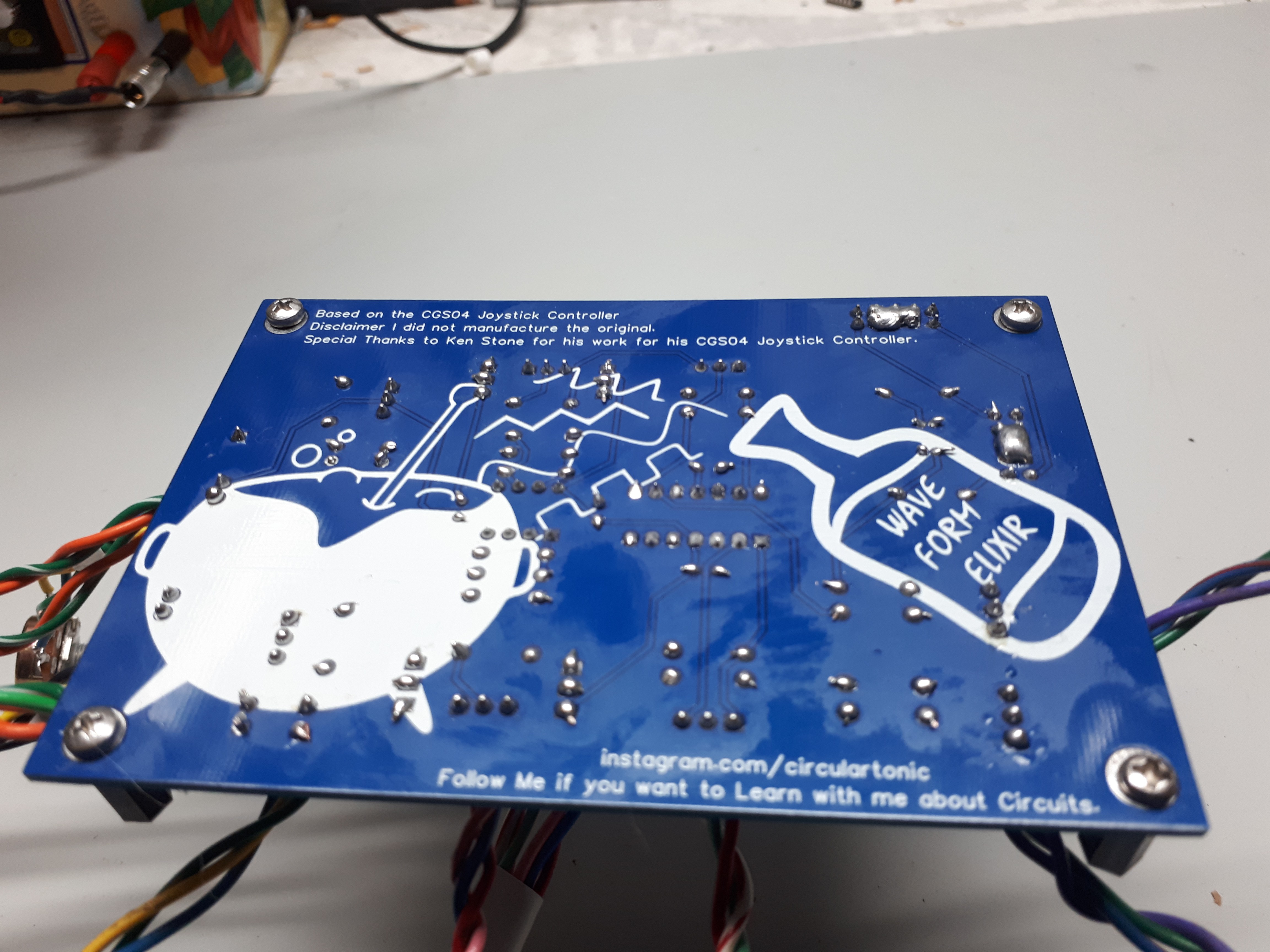
Also going to release the PCB files once finalized and maybe do some limited runs.
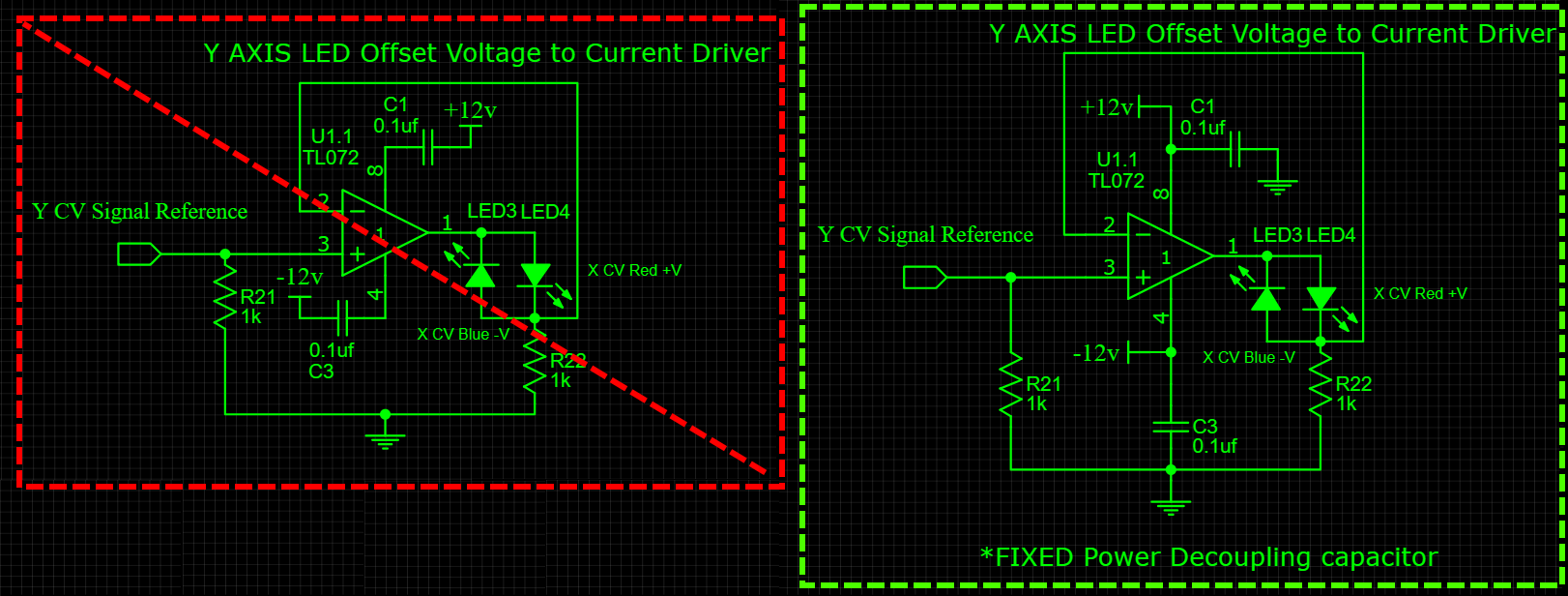
 There in v1.3.1 there is a option to add a always inverted switch. So this simple mod you can add it if you want.
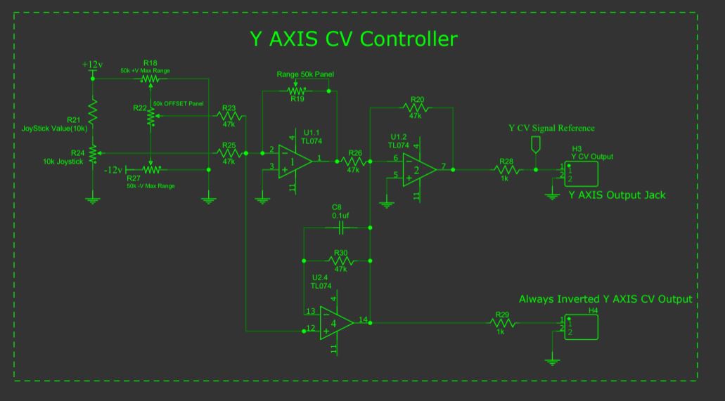


 Tim
Tim
 Jasper Sikken
 Stefan-Xp
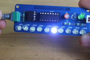
 sandy
sandy
Looks like a great rendition of the joystick controller idea, do you have any plans to release your PCB files, before I attempt to redraw the schematic in kicad...